1995 NISSAN ALMERA N15 warning
[x] Cancel search: warningPage 7 of 1701

PREPARATIONANDPRECAUTIONS
Service Notice
Supplemental RestraintSystem(SRS)"AIR
BAG" (DualAirBag System)
The Supplemental RestraintSystem"AirBag" usedalong withaseat belt, helps toreduce therisk or
severity ofinjury tothe driver andfront passenger inafrontal collision. TheSupplemental Restraint
System consists ofair bag modules (locatedinthe center ofthe steering wheelandonthe instrument
panel onthe passenger side),adiagnosis sensorunit,warning lamp,wiring harness andspiral cable.
Information necessarytoservice thesystem safelyisincluded inthe
RSsection
ofthis Service Manual.
WARNING:
• Toavoid rendering theSRS inoperative, whichcouldincrease therisk ofpersonal injuryordeath
in the event ofacollision whichwould resultinair bag inflation, allmaintenance mustbeperformed
by an authorized NISSANdealer.
• Improper maintenance, includingincorrectremovalandinstallation ofthe SRS, canlead topersonal
injury caused byunintentional activationofthe system.
Ii
Donot use electrical testequipment onany circuit related tothe SRS unless instructed tointhis
Service Manual. SRSwiring harnesses arecovered withyellow insulation eitherjustbefore the
harness connectors orfor the complete harness,foreasy identification.
•
Before proceeding withdisassembly, thor-
oughly cleantheoutside ofthe transaxle. Itis
important toprevent theinternal partsfrom
becoming contaminated bydirt orother for-
eign matter.
• Disassembly shouldbedone inaclean work
area.
• Use lint-free clothortowels forwiping parts
clean. Common shopragscanleave fibers
that could interfere withtheoperation ofthe
transaxle.
• Place disassembled partsinorder, onaparts
rack, foreasier andproper assembly.
• Allparts should becarefully cleaned-witha
general purpose, non-flammable solvent
before inspection orreassembly.
• Gaskets, sealsandO-rings shouldbe
replaced anytime thetransaxle isdisassem-
bled.
• Itis very important toperform functional tests
whenever theyareindicated. •
The valve bodycontains precision partsand
requires extremecarewhen partsare
removed andserviced. Placedisassembled
valve bodyparts inorder, onaparts rack,for
easier andproper assembly. Carewillalso
prevent springs andsmall partsfrombecom-
ing scattered orlost.
• Properly installedvales,sleeves, plugs,etc.
will slide along theirbores inthe valve body
under theirownweight.
• Before assembly, applyacoat ofrecom-
mended ATFtoall parts. Apply petroleum
jelly toprotect O-ringandseals, orhold bear-
ings andwashers inplace during assembly.
Do not use grease.
• Extremely careshould betaken toavoid dam-
age toO-rings, sealsandgaskets when
assembling.
• After overhaul, refillthetransaxle withnew
ATF.
•
Supplemental RestraintSystem(SRS)"AIR
BAG" (Single AirBag System)
The Supplemental RestraintSystem"AirBag" andused along withaseat belt,helps toreduce therisk
or severity ofinjury tothe driver inafrontal collision. TheSupplemental RestraintSystemconsists of
an air bag module (located inthe center ofthe steering wheel),adiagnosis sensorunit,warning lamp,
wiring harness andspiral cable. Information necessarytoservice thesystem safelyisincluded inthe
RS section
ofthis Service Manual.
WARNING:
• Toavoid rendering theSRS inoperative, whichcouldincrease therisk ofpersonal injuryordeath
in the event ofacollision whichwould resultinair bag inflation, allmaintenance mustbeperformed
by an authorized NISSANdealer.
• Improper maintenance, includingincorrectremovalandinstallation ofthe SRS, canlead topersonal
injury caused byunintentional activationofthe system.
• Donot use electrical testequipment onany circuit related tothe SRS unless instructed tointhis
Service Manual.
AT-7
Page 222 of 1701

PRECAUTIONS
Service Notice
• When removing orinstalling variousparts,placeacloth orpadding ontothevehicle bodytoprevent
scratches.
• Handle trim,molding, instruments, grille,etc.carefully duringremoving orinstalling. Becareful not
to soil ordamage them.
• Apply sealing compound wherenecessary wheninstalling parts.
• When applying sealingcompound, becareful thatthesealing compound doesnotprotrude from
parts.
• When replacing anymetal parts(forexample bodyouter panel, members, etc.),besure totake rust
prevention measures.
SupplementalRestraintSystem(SRS)"AIR
BAG" (DualAirBag System)
The Supplemental RestraintSystem"AirBag", usedalong withaseat belt,helps toreduce therisk or
severity ofinjury tothe driver andfront passenger inafrontal collision. TheSupplemental Restraint
System consists ofair bag modules (locatedinthe center ofthe steering wheelandonthe instrument
panel onthe passenger side),adiagnosis sensorunit,warning lamp,wiring harness andspiral cable.
Information necessarytoservice thesystem safelyisincluded inthe
RSsection
ofthis Service Manual.
WARNING:
• Toavoid rendering theSRS inoperative, whichcouldincrease therisk ofpersonal injuryordeath
in the event ofacollision whichwould resultinair bag inflation, allmaintenance mustbeperformed
by an authorized NISSANdealer.
• Improper maintenance, includingincorrectremovalandinstallation ofthe SRS, canlead topersonal
injury caused byunintentional activationofthe system.
• Donot use electrical testequipment onany circuit related tothe SRS unless instructed tointhis
Service Manual. SRSwiring harnesses arecovered withyellow insulation eitherjustbefore the
harness connectors orfor the complete harness,foreasy identification.
Supplemental RestraintSystem(SRS)"AIR
BAG" (Single AirBag System)
The Supplemental RestraintSystem"AirBag", usedalong withaseat belt,helps toreduce therisk or
severity ofinjury tothe driver inafrontal collision. TheSupplemental RestraintSystemconsists ofan
air bag module (located inthe center ofthe steering wheel),adiagnosis sensorunit,warning lamp,
wiring harness andspiral cable. Information necessarytoservice thesystem safelyisincluded inthe
RS section
ofthis Service Manual.
WARNING:
• Toavoid rendering theSRS inoperative, whichcouldincrease therisk ofpersonal injuryordeath
in the event ofacollision whichwould resultinair bag inflation, allmaintenance mustbeperformed
by an authorized NISSANdealer.
• Improper maintenance, includingincorrectremovalandinstallation ofthe SRS, canlead topersonal
injury caused byunintentional activationofthe system.
• Donot use electrical testequipment onany circuit related tothe SRS unless instructed tointhis
Service Manual.
BT-2
Page 229 of 1701
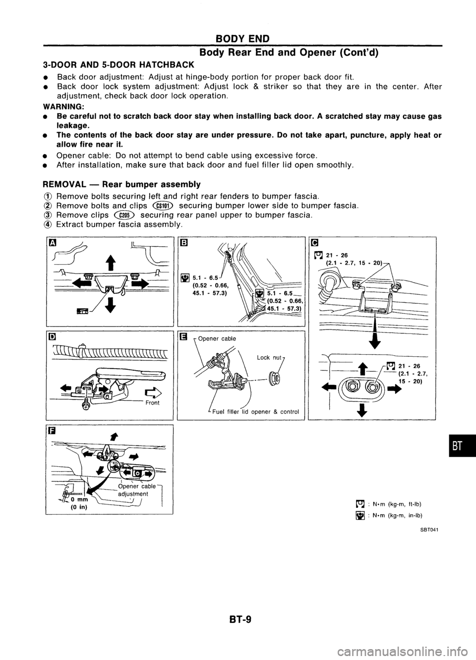
BODYEND
Body RearEndandOpener (Cont'd)
3-DOOR AND5-DOOR HATCHBACK
• Back dooradjustment: Adjustathinge-body portionforproper backdoorfit.
• Back doorlocksystem adjustment: Adjustlock
&
striker sothat they areinthe center. After
adjustment, checkbackdoor lockoperation.
WARNING:
• Becareful nottoscratch backdoor staywhen installing backdoor. Ascratched staymay cause gas
leakage.
• The contents ofthe back doorstayareunder pressure. Donot take apart, puncture, applyheator
allow firenear it.
• Opener cable:Donot attempt tobend cable usingexcessive force.
• After installation, makesurethatback doorandfuel filler lidopen smoothly.
REMOVAL -Rear bumper assembly
(1)
Remove boltssecuring leftand right rearfenders tobumper fascia.
@
Remove boltsandclips
@ill>
securi-ng bumperlowersidetobumper fascia.
@)
Remove clips~ securing rearpanel upper tobumper fascia.
@
Extract bumper fasciaassembly.
rn
~\\\\\\\\\\\\\\\\\\\\\\
I,"-
1f;
Openercable
l
'\ '--- adju~~m~nl
omm~
(0
in)
B1-9
[O.J
:
N.m (kg-m, Il-Ib)
~ :N'm (kg-m, in-Ib)
SBT041
•
Page 263 of 1701
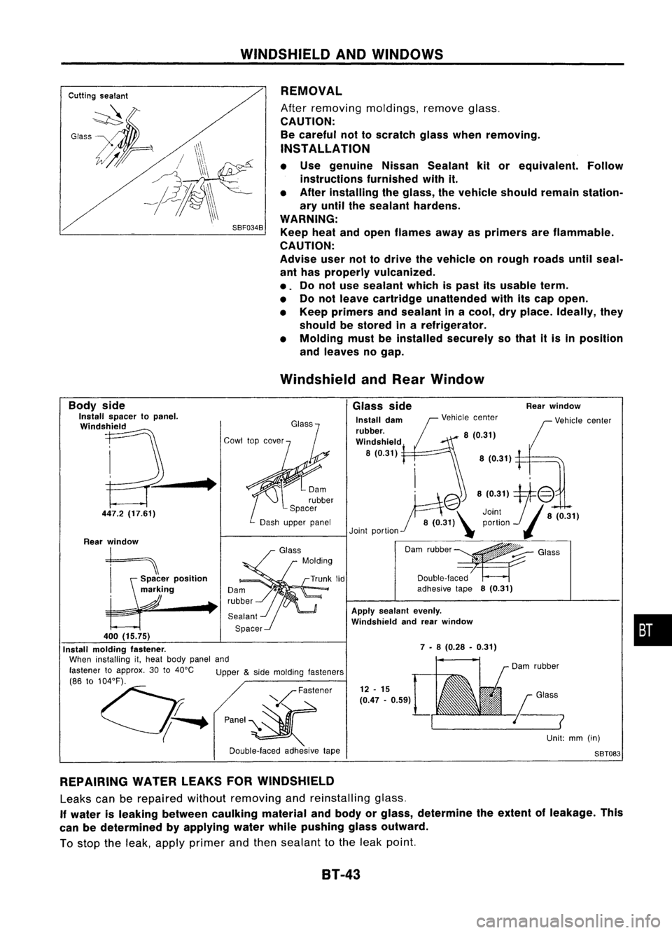
WINDSHIELDANDWINDOWS
Cutting sealant
SBF034BREMOVAL
After removing moldings, removeglass,
CAUTION: Be careful nottoscratch glasswhen removing.
INSTALLATION
• Use genuine NissanSealant kitorequivalent. Follow
instructions furnishedwithit.
• After installing theglass, thevehicle shouldremain station-
ary until thesealant hardens.
WARNING: Keep heatandopen flames awayasprimers areflammable.
CAUTION:
Advise usernottodrive thevehicle onrough roadsuntilseal-
ant has properly vulcanized.
•. Donot use sealant whichispast itsusable term.
• Donot leave cartridge unattended withitscap open.
• Keep primers andsealant inacool, dryplace. Ideally, they
should bestored inarefrigerator.
• Molding mustbeinstalled securely sothat itis in position
and leaves nogap.
Windshield andRear Window
•
Rear
window
Vehicle center
8 (0.31)
Glass
side
Install dam
rubber.
Windshield
8(0.31)
12 -15
(0.47 -0.59)
Apply
sealant evenly.
Windshield andrear window
7 •8 (0.28 •0.31)
Unit:mm(in)
S8T083
fj
'@8(0.31)1:@
Joint8(0.31)
8 (0.31)\ portion
(J
Joint portion "
O,m ,"bb"~
G,,,,
Double-laced
adhesive tape8(0.31)
V
Fastener
P'""~
Double-laced
adhesive
tape
•
Body
side
Install spacer topanel.
Windshield
447.2 (17.61)
Rear window
t==\
h¥:~'
po"II"
markmg
•
400 (15.75)
Install molding fastener.
When installing it,heat body panel and
fastener toapprox. 30to40°C Upper
&
side molding lasteners
(86 to104°F).
0;-.
REPAIRING WATERLEAKSFORWINDSHIELD
Leaks canberepaired withoutremoving andreinstalling glass.
If water isleaking between caulking materialandbody orglass, determine theextent ofleakage. This
can bedetermined byapplying waterwhilepushing glassoutward.
To stop theleak, apply primer andthen sealant tothe leak point.
81-43
Page 273 of 1701

PRECAUTIONSANDPREPARATION
Precautions
SUPPLEMENTAL RESTRAINTSYSTEM(SRS)"AIRBAG"
(DUAL AIRBAG SYSTEM)
The Supplemental RestraintSystem"AirBag" usedalong with
a seat belt,helps toreduce therisk orseverity ofinjury tothe
driver andfront passenger inafrontal collision. TheSupple-
mental Restraint Systemconsists ofair bag modules (located
in the center ofthe steering wheelandonthe instrument panel
on the passenger side),adiagnosis sensorunit,warning lamp,
wiring harness andspiral cable. Information necessarytoser-
vice thesystem safelyisincluded inthe
RSsection
ofthis Ser-
vice Manual.
WARNING:
• Toavoid rendering theSRS inoperatiYe, whichcouldincrease therisk ofpersonal injuryordeath
in the event ofacollision whichwould resultinair bag inflation, allmaintenance mustbeperformed
by an authorized NISSANdealer.
• Improper maintenance, includingincorrectremovalandinstallation ofthe SRS, canlead topersonal
injury caused byunintentional activationofthe system.
• Donot use electrical testequipment onany circuit related tothe SRS unless instructed tointhis
Service Manual. SRSwiring harnesses arecovered withyellow insulation eitherjustbefore the
harness connectors orfor the complete harness,foreasy identification.
SUPPLEMENTAL RESTRAINTSYSTEM(SRS)"AIRBAG"
(SINGLE AIRBAG SYSTEM)
The Supplemental RestraintSystem"AirBag" andused along withaseat belt,helps toreduce therisk
or severity ofinjury tothe driver inafrontal collision. TheSupplemental RestraintSystemconsists of
an air bag module (located inthe center ofthe steering wheel),adiagnosis sensorunit,warning lamp,
wiring harness andspiral cable. Information necessarytoservice thesystem safelyisincluded inthe
RS section
ofthis Service Manual.
WARNING:
• Toavoid rendering theSRS inoperative, whichcouldincrease therisk ofpersonal injuryordeath
in the event ofacollision whichwould resultinair bag inflation, allmaintenance mustbeperformed
by an authorized NISSANdealer.
• Improper maintenance, includingincorrectremovalandinstallation ofthe SRS, canlead topersonal
injury caused byunintentional activationofthe system.
• Donot use electrical testequipment onany circuit related tothe SRS unless instructed tointhis
Service Manual.
BR-3
•
Page 274 of 1701
GG94310000or
commercial equivalent
SBR820BA
For
tightening flarenut
Tool number
Tool name
PRECAUTIONS
ANDPREPARATION
Precautions (Conl'd)
BRAKE SYSTEM
• Recommended fluidisbrake fluid"DOT 3"or"DOT 4".
• Never reusedrained brakefluid.
• Donot mix different typesofbrake fluids (DOT3,DOT 4).
• Becareful nottosplash brakefluidonpainted areas;itmay
cause paintdamage. Ifbrake fluidissplashed onpainted
areas, washitaway withwater immediately.
• Toclean master cylinder parts,discbrake caliper partsor
wheel cylinder parts,useclean brake fluid.
• Never usemineral oilssuch asgasoline orkerosene. They
will ruin rubber partsofhydraulic system.
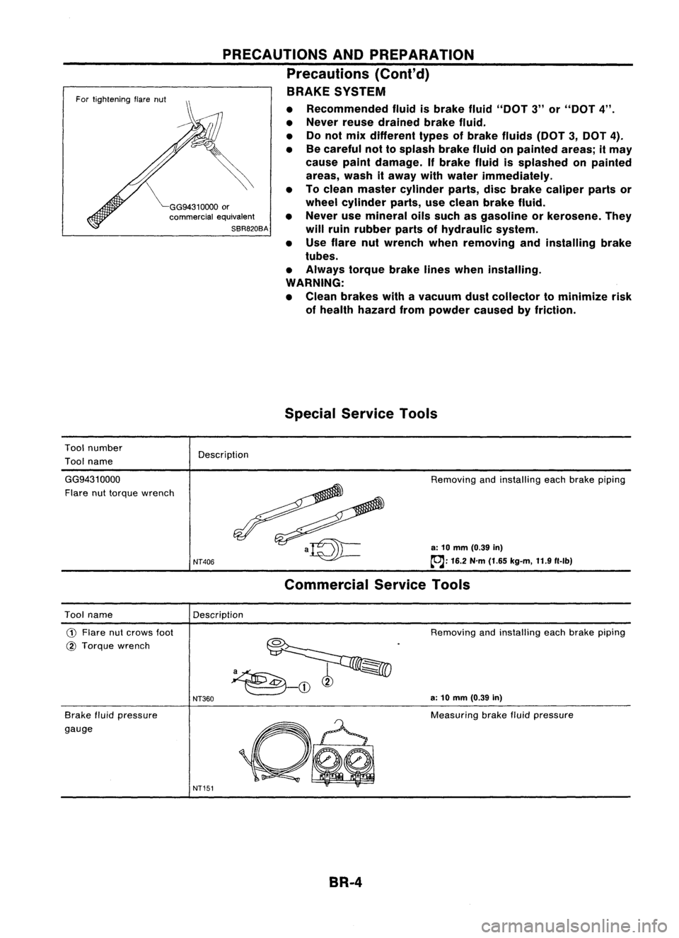
• Use flare nutwrench whenremoving andinstalling brake
tubes.
• Always torquebrakelineswhen installing.
WARNING:
• Clean brakes withavacuum dustcollector tominimize risk
of health hazard frompowder causedbyfriction.
Special Service Tools
Description
GG9431 0000
Flare nuttorque wrench
NT406
Removing
andinstalling eachbrake piping
a: 10 mm (0.39 in)
~: 16.2N'm(1.65 kg-m, 11.9f1-lb)
Commercial ServiceTools
Description
Tool name
CD
Flare nutcrows foot
@ Torque wrench
Brake fluidpressure
gauge
NT360
NT151
Removing
andinstalling eachbrake piping
a: 10 mm (0.39 in)
Measuring brakefluidpressure
BR-4
Page 275 of 1701
CHECKANDADJUSTMENT
OK
MINMax.
line
Min. line
SBR418C
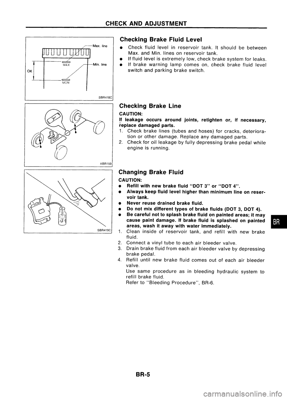
Checking
BrakeFluidLevel
• Check fluidlevel inreservoir tank.Itshould bebetween
Max. andMin. lines onreservoir tank.
• Iffluid level isextremely low,check brakesystem forleaks.
• Ifbrake warning lampcomes on,check brakefluidlevel
switch andparking brakeswitch.
ABR159
SBR419C
Checking
BrakeLine
CAUTION: If leakage occursaround joints,retighten or,ifnecessary,
replace damaged parts.
1. Check brakelines(tubes andhoses) forcracks, deteriora-
tion orother damage. Replaceanydamaged parts.
2. Check foroilleakage byfully depressing brakepedalwhile
engine isrunning.
Changing BrakeFluid
CAUTION:
• Refill withnewbrake fluid"DOT 3"or"DOT 4".
• Always keepfluidlevel higher thanminimum lineonreser-
voir tank.
• Never reusedrained brakefluid.
• Donot mix different typesofbrake fluids(DOT3,DOT 4).
• Becareful nottosplash brakefluidonpainted areas;itmay •
cause paintdamage. Ifbrake fluidissplashed onpainted :•
areas, washitaway withwater immediately.
1. Clean inside ofreservoir tank,andrefill withnewbrake
fluid.
2. Connect avinyl tubetoeach airbleeder valve.
3. Drain brake fluidfrom each airbleeder valvebydepressing
brake pedal.
4. Refill untilnewbrake fluidcomes outofeach airbleeder
valve.
Use same procedure asinbleeding hydraulic systemto
refill brake fluid.
Refer to"Bleeding Procedure", BR-6.
BR-5
Page 288 of 1701
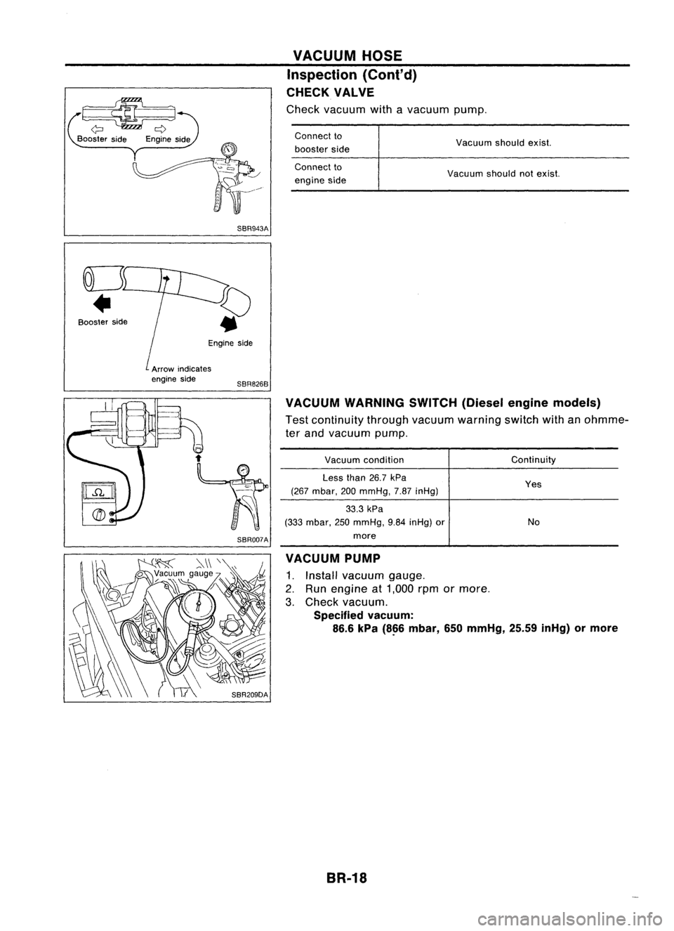
VACUUMHOSE
Inspection (Cont'd)
CHECK VALVE
Check vacuum withavacuum pump.
~
Booster side
SBR943A
Connect
to
booster side
Connect to
engine side Vacuum
shouldexist.
Vacuum shouldnotexist.
Engine side
VACUUM WARNING SWITCH(Dieselenginemodels)
Test continuity throughvacuum warning switchwithanohmme-
ter and vacuum pump.
Booster
side
Arrowindicates
engine side
SBR826B
SBR007A
Vacuum
condition
Less than26.7kPa
(267 mbar, 200mmHg, 7.87inHg)
33.3 kPa
(333 mbar, 250mmHg, 9.84inHg) or
more Continuity
Yes
No
VACUUM PUMP
1. Install vacuum gauge.
2. Run engine at1,000 rpmormore.
3. Check vacuum.
Specified vacuum:
86.6 kPa
(8~6
mbar, 650mmHg, 25.59inHg) ormore
BR-18