1995 NISSAN ALMERA N15 oil temperature
[x] Cancel search: oil temperaturePage 19 of 1701
TROUBLEDIAGNOSES
Road Testing (Cont'd)
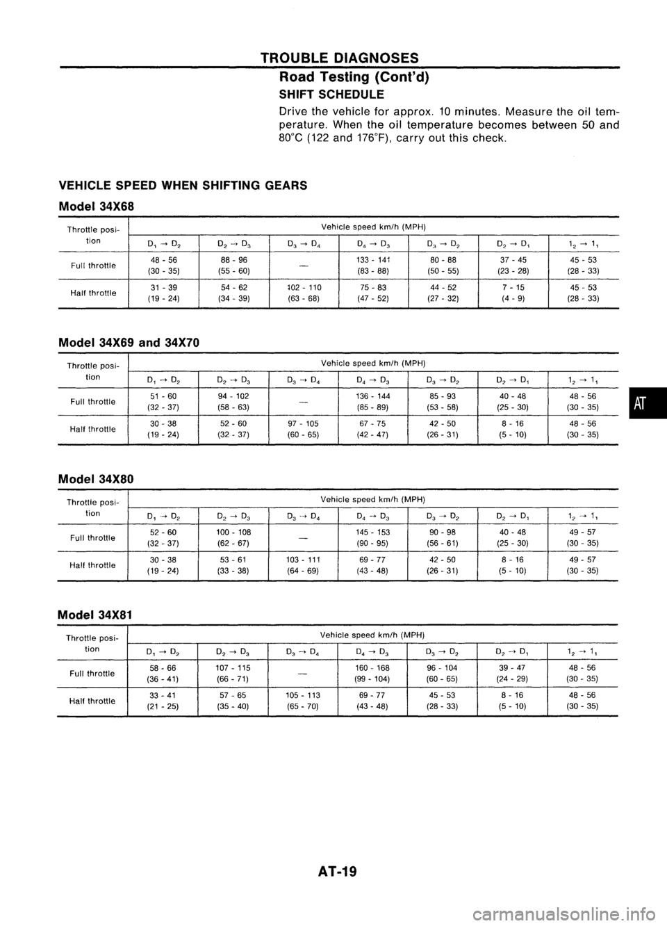
SHIFT SCHEDULE
Drive thevehicle forapprox. 10minutes. Measuretheoiltem-
perature. Whentheoiltemperature becomesbetween50and
80°C (122and176°F), carryoutthis check.
VEHICLE SPEEDWHENSHIFTING GEARS
Model 34X68
Throttle posi- Vehicle
speedkm/h(MPH)
tion
0,~O
2
O
2
->
0
3
0
3
->
0
4
0
4
~
0
3
0
3
->
O
2
O
2
->
0,
1
2
~
1,
Full throttle
48
-56 88
-96 133
-141
80-88 37-45 45-53
(30 -35) (55-60)
-
(83-88)
(50-55) (23-28) (28
-33)
Half throttle
31
-39 54
-62 102-110
75-83 44
-52
7-15 45
-53
(19 -24) (34
-39)
(63-68) (47
-52)
(27-32) (4
-9)
(28-33)
Model 34X69and34X70
Throttle pas
i-
Vehicle
speedkm/h(MPH)
tion
0,~O
2
O
2~
0
3
0
3
->
0
4
0
4~
0
3
0
3
->
O
2
O
2~
0,
1
2~
1,
Full throttle
51
-60 94
-102 136-144
85-93 40
-48
48-56
(32 -37) (58-63)
-
(85-89)
(53-58) (25
-30) (30-35)
Half throttle
30
-38 52
-60 97-105 67-75 42-50 8-16
48-56
(19 -24) (32-37) (60-65) (42-47) (26-31) (5-10) (30-35)
Model 34X80
Throttle posi- Vehicle
speedkm/h(MPH)
tion
0,~O
2
O
2
->
0
3
0
3~
0
4
0
4
->
0
3
0
3
~
O
2
O
2
->
0,
1"
->
1,
Full throttle
52
-60 100-108 145
-153
90-98 40
-48 49-57
(32 -37) (62-67)
-
(90-95) (56-61) (25-30) (30
-35)
Half throttle
30
-38 53-61 103
-111
69-77 42
-50 8-16 49-57
(19 -24) (33-38) (64-69) (43-48) (26-31) (5-10) (30-35)
Model 34X81
Throttle posi- Vehicle
speedkm/h(MPH)
tion
0,~O
2
O
2
->
0
3
0
3
~
0
4
0
4
->
0
3
0
3
->
O
2
O
2
~
0,
1
2~
1,
Full throttle
58
-66 107
-115 160
-168
96-104 39
-47 48-56
(36 -41) (66
-71)
-
(99-104) (60-65) (24
-29) (30
-35)
33 -41 57-65 105
-113 69-77 45-53 8-16 48-56
Half throttle
(21-25) (35-40)
(65-70) (43
-48) (28-33) (5-10) (30
-35)
AT-19
•
Page 24 of 1701
TROUBLEDIAGNOSES
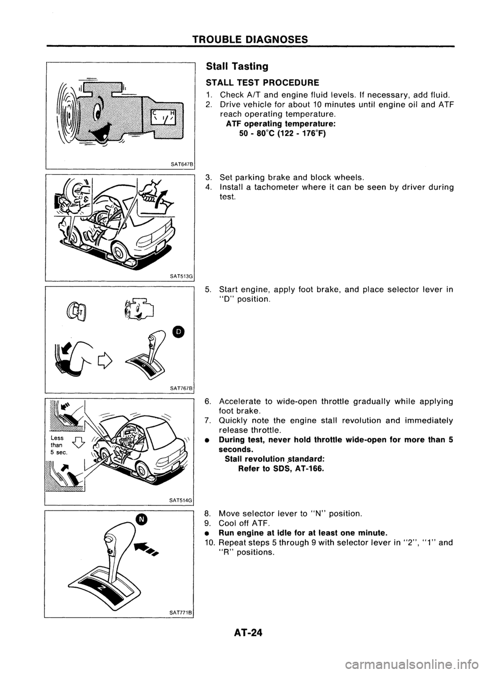
Stall Tasting
STALL TESTPROCEDURE
1. Check
AIT
and engine fluidlevels. Ifnecessary, addfluid.
2. Drive vehicle forabout 10minutes untilengine oiland ATF
reach operating temperature.
ATF operating temperature:
50 -80
0
e (122-176°F)
SAT6478
3.Set parking brakeandblock wheels.
4. Install atachometer whereitcan beseen bydriver during
test.
SAT513G 5.
~ ~ID
•
~c;>
SAT7678
Start
engine, applyfootbrake, andplace selector leverin
"0"
position.
6. Accelerate towide-open throttlegradually whileapplying
foot brake.
7. Quickly notetheengine stallrevolution andimmediately
release throttle.
• During test,never holdthrottle wide-open formore than5
seconds. Stall revolution .standard:
Refer toSDS, AT-166.
SAT514G
8.Move selector leverto"N" position.
9. Cool offATF.
• Run engine atidle foratleast oneminute.
10. Repeat steps5through 9with selector leverin"2", "1"and
"R
n
positions.
SAT7718 AT-24
Page 26 of 1701
TROUBLEDIAGNOSES
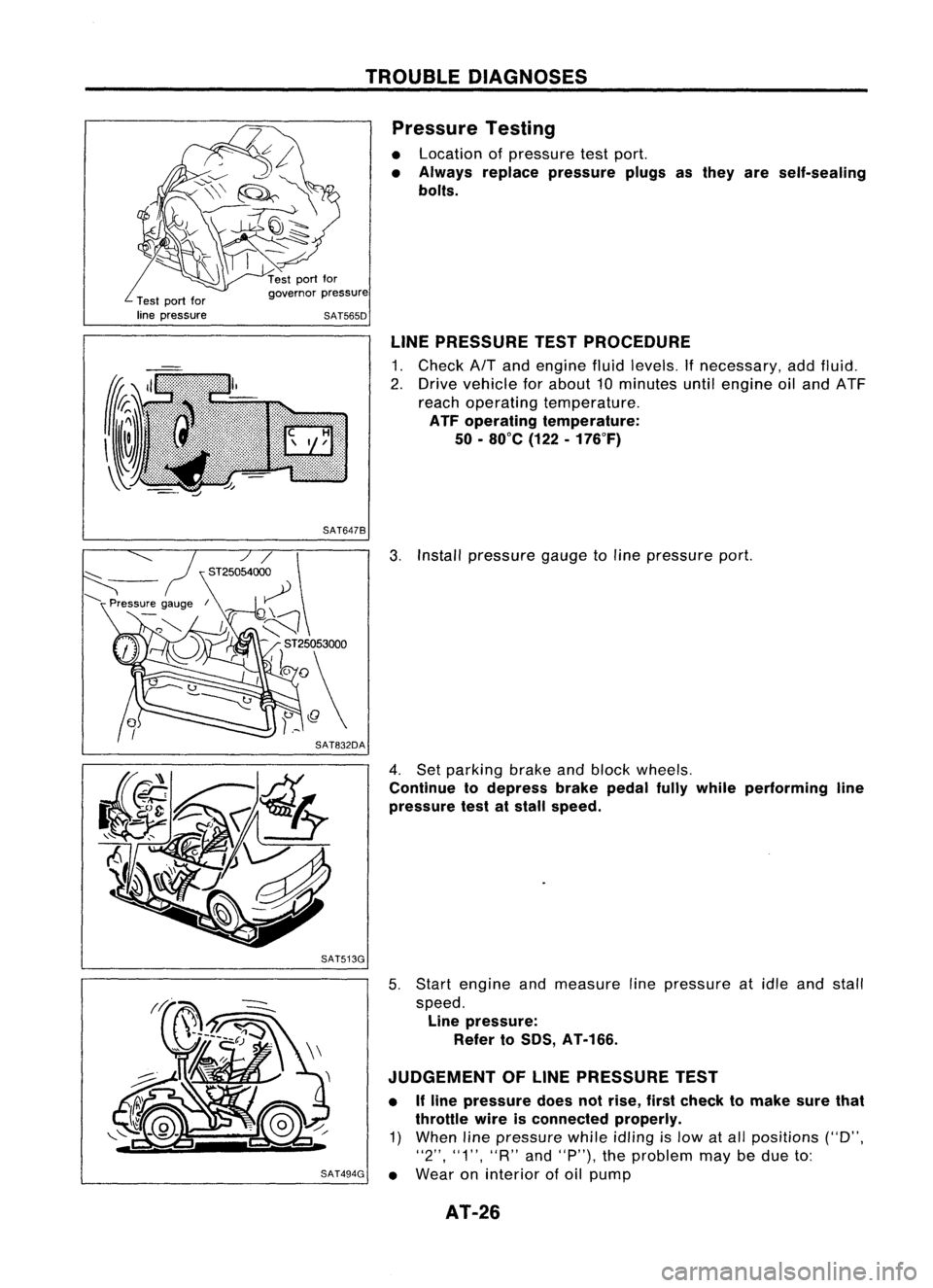
Pressure Testing
• Location ofpressure testport.
• Always replace pressure plugsasthey areself-sealing
bolts.
Test portfor
line pressure governor
pressure
SAT565D
LINEPRESSURE TESTPROCEDURE
1. Check AfTand engine fluidlevels. Ifnecessary, addfluid.
2. Drive vehicle forabout 10minutes untilengine oiland ATF
reach operating temperature.
ATF operating temperature:
50 -80°C (122-176°F)
SAT647B
3.Install pressure gaugetoline pressure port.
4. Set parking brakeandblock wheels.
Continue todepress brakepedalfullywhile performing line
pressure testatstall speed.
SAT513G
5.Start engine andmeasure linepressure atidle and stall
speed. Line pressure:
Refer toSOS, AT-166.
JUDGEMENT OFLINE PRESSURE TEST
• Ifline pressure doesnotrise, firstcheck tomake surethat
throttle wireisconnected properly.
1) When linepressure whileidling
is
low atall positions ("D",
"2", "1", "R"and"P"), theproblem maybedue to:
SAT494G •
Wear oninterior ofoil pump
AT-26
Page 27 of 1701
'-)
(
~)o
Front
SAT498GTROUBLE
DIAGNOSES
Pressure Testing(Cont'd)
• Oilleakage ator around oilpump, control valvebody, trans-
mission caseorgovernor
• Sticking pressure regulator valve
• Sticking pressure modifiervalve
2) When linepressure whileidling islow ataparticular
position, checkthefollowing.
• Ifoil leaks ator around low
&
reverse brakecircuit, line
pressure becomes lowin"R" position. Butline pressure is
normal in"P", "D", "2"or"1" position.
3) When linepressure ishigh while idling, pressure regulator
valve mayhave stuck.
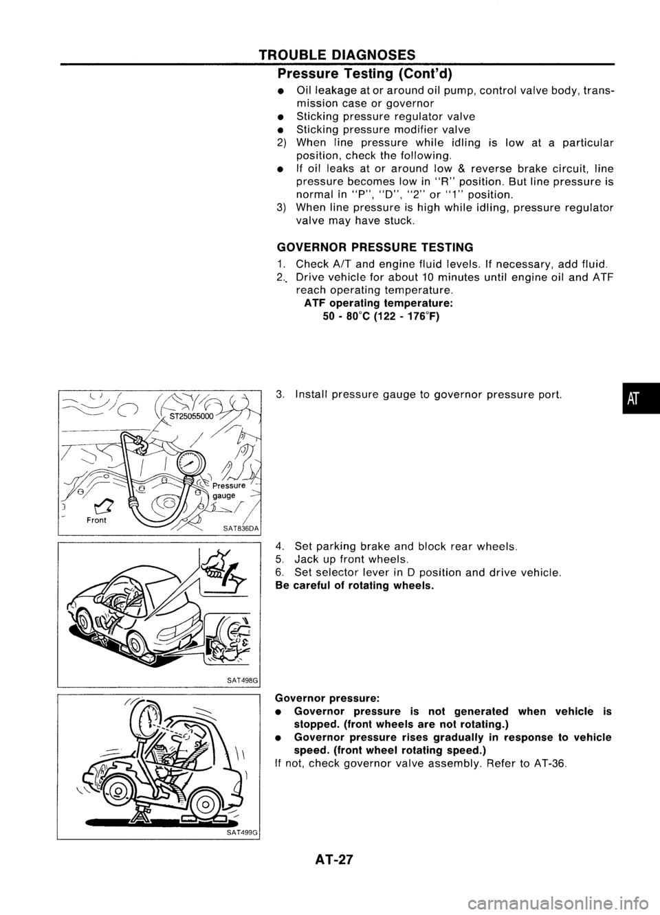
GOVERNOR PRESSURETESTING
1. Check
AIT
and engine fluidlevels. Ifnecessary, addfluid.
2 .. Drive vehicle forabout 10minutes untilengine oiland ATF
reach operating temperature.
ATF operating temperature:
50 -80°C (122-176°F)
3. Install pressure gaugetogovernor pressureport.
4. Set parking brakeandblock rearwheels.
5. Jack upfront wheels.
6. Set selector leverinDposition anddrive vehicle.
Be careful ofrotating wheels.
•
Governor pressure:
• Governor pressureisnot generated whenvehicle is
stopped. (frontwheels arenotrotating.)
• Governor pressurerisesgradually inresponse tovehicle
speed. (frontwheel rotating speed.)
If not, check governor valveassembly. RefertoAT-36.
AT-27
Page 374 of 1701

CONTENTS(Conl'd.)
Front FogLamp Aiming Adjustment.. 101
Rear FogLamp/Wiring Diagram-R/FOG -102
Turn Signal andHazard Warning Lamps/
Schematic 106
Turn Signal andHazard Warning
Lamps/Wiring Diagram-TURN - 107
Turn Signal andHazard Warning
Lamps/Trouble Diagnoses 113
Combination FlasherUnitCheck 113
Bulb Specifications 114
INTERIOR LAMP 115
Illumination/Schematic 115
Illumination/Wiring Diagram-ILL - 116
Interior, Spot,Trunk Room andLuggage
Room Lamps/Wiring Diagram-INT/L - 122
Bulb Specifications 126
METER ANDGAUGES 127
Combination Meter 127
Speedometer, Tachometer,Temp.andFuel
Gauges/Wiring Diagram-METER - 129
Inspection/Fuel GaugeandWater
Temperature Gauge 133
Inspection/Tachometer 134
Inspection/Speedometer andVehicle Speed
Sensor 135
Fuel Tank Gauge UnitCheck 137
Thermal Transmitter Check 137
Vehicle SpeedSensor SignalCheck 137
WARNING LAMPSANDBUZZER 138
Warning Lamps/Schematic 138
Warning Lamps/Wiring Diagram-WARN -139
Oil Pressure SwitchCheck 151
Fuel Warning LampSensor Check 151
Diode Check 151
Warning BuzzerUnit... 151
Warning Buzzer/System Description 152
Warning Buzzer/Wiring Diagram
- BUZZER - 154
Components Inspection-Warning Buzzer 157
WIPER ANDWASHER 160
Front Wiper andWasher/System Description160
Front Wiper andWasher/Wiring Diagram
- WIPER - 162
Front Wiper Amplifier Check 166
Front Wiper Installation andAdjustment.. 166
Front Wiper Linkage 167
Front Washer NozzleAdjustment... 168
Front Washer TubeLayout 168
Rear Wiper andWasher/System Description169Rear
Wiper andWasher/Wiring Diagram
- WIP/R - 171
Rear Wiper Amplifier Check 175
Rear Wiper Installation andAdjustment.. 175
Rear Washer NozzleAdjustment 175
Rear Washer TubeLayout.. 176
Check Valve(forrear washer) 176
Headlamp WiperandWasher/Wiring Diagram
- HLC - 177
Headlamp WiperMotorCheck 179
Headlamp WiperInstallation 179
Headlamp WasherTubeLayout.. 179
Check Valve(Forheadlamp washer) 179
POWER WINDOW 180
System Description 180
Schematic 183
Wiring Diagram -WINDOW - 185
Trouble Diagnoses 197
POWER DOORLOCK 198
System Description 198
Schematic 200
Wiring Diagram -D/LOCK - 202
Trouble Diagnoses -Type 1(For Europe and
Austral ia) 212
Trouble Diagnoses -Type 2(Except for
Europe andAustralia) 216
POWER DOORMIRROR 220
Wiring Diagram -MIRROR - 220
ELECTRIC SUNROOF 224
Wiring Diagram -SROOF - 224
HORN, CIGARETTE LIGHTERANDCLOCK 226
Wiring Diagram -HORN - 226
REAR WINDOW DEFOGGER ANDDOOR
MIRROR DEFOGGER 230
System Description (Formodels withdaytime
light system) 230
Wirin.g Diagram -DEF - 231
Filament Check 235
Fi lament Repai
r
236
AUDIO ANDANTENNA 237
Audio/System Description 237
Wiring Diagram -AUDIO - 238
Radio FuseCheck 243
Location ofAntenna 243
Antenna RodReplacement.. 243
HEATED SEAT 245
Wiring Diagram -H/SEAT - 245
NATS (Nissan Anti-Theft System) 247
System Description 247
System Composition 247
Page 410 of 1701
![NISSAN ALMERA N15 1995 Service Manual STARTINGSYSTEM
Construction (Cont'd)
SEC. 233
S114.568A
S114-630
Unit: mm(in)
fj] :
N.m (kg-m, in-Ib)
m@ :
High-temperature greasepointDust
cover (Adjusting plate)
Plate
thickness:
0.5 (0.02 NISSAN ALMERA N15 1995 Service Manual STARTINGSYSTEM
Construction (Cont'd)
SEC. 233
S114.568A
S114-630
Unit: mm(in)
fj] :
N.m (kg-m, in-Ib)
m@ :
High-temperature greasepointDust
cover (Adjusting plate)
Plate
thickness:
0.5 (0.02](/manual-img/5/57349/w960_57349-409.png)
STARTINGSYSTEM
Construction (Cont'd)
SEC. 233
S114.568A
S114-630
Unit: mm(in)
fj] :
N.m (kg-m, in-Ib)
m@ :
High-temperature greasepointDust
cover (Adjusting plate)
Plate
thickness:
0.5 (0.020)
0.8 (0.031)
Field coil
•
7.4.9.8 (0.75•1.00. 65.1.86.8)
• 4.9.6.4
(0.50 •0.65. 43.4•56.4)
E-ring
SEL249SC
SEC. 233
M3T37783
Gearcase
Gear casemetal
m
@
Adjusting
plate
Plate
thickness:
0.25 (0.0098)
0.50 (0.0197)
Armature
Unit: mm(in)
fj]:
N.m(kg-m. in-Ib)
m
@:
High-temperature greasepoint
EL-38
IiJ
2.5-4.4
r.ilI
(0.25-0.45.
~ 4.4•7.1 21.7•39.1)
(0.45 •0.72.
~
SEL464PA
Page 412 of 1701
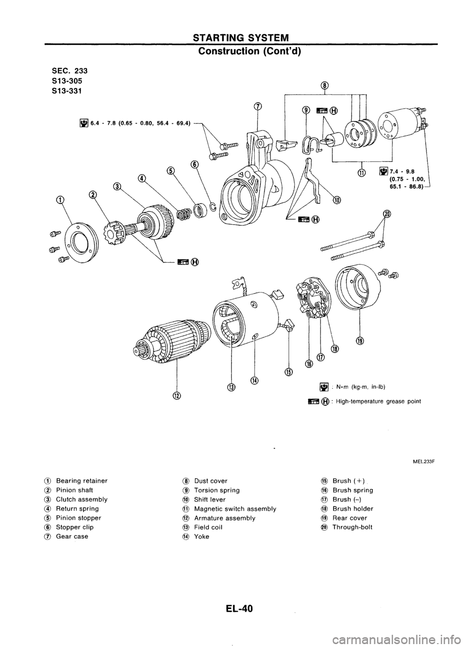
STARTINGSYSTEM
Construction (Cont'd)
5EC. 233
513-305
513-331
Iil!J
'.4 .7.8 (0.'5 -0.80, 56.4-88.4) ~
6
8
~7.4.9.8
(0.75 -1.00,
65.1 -86.8)
~ .N.m (kg-m, in-Ib)
m
@:
High-temperature greasepoint
MEL233F
CD
Bearing retainer
@
Pinion shaft
@
Clutch assembly
@
Return spring
@
Pinion stopper
@
Stopper clip
(J)
Gear case
@
Dust cover
@
Torsion spring
@)
Shift lever
@
Magnetic switchassembly
@
Armature assembly
@
Field coil
@
Yoke
EL-40 @
Brush
(+)
@)
Brush spring
@
Brush
H
@
Brush holder
@
Rear cover
@)
Through-bolt
Page 721 of 1701
CONTENTS(Cont'd.)
CONSULT Reference ValueinData Monitor
Mode 74
Major Sensor Reference GraphinData
Monitor Mode 76
ECM Terminals andReference Value 78
TROUBLE DIAGNOSIS FORPOWER SUPPLY 88
Main Power Supply andGround Circuit.. 88
TROUBLE DIAGNOSIS FORDTC11 94
Camshaft PositionSensor(CMPS) 94
TROUBLE DIAGNOSIS FORDTC
12 101
Mass AirFlow Sensor (MAFS) 101
TROUBLE DIAGNOSIS FORDTC
13 108
Engine Coolant Temperature Sensor(ECTS) 108
TROUBLE DIAGNOSIS FORDTC
21 113
Ignition Signal 113
TROUBLE DIAGNOSIS FORDTC
34 119
Knock Sensor (KS) 119
TROUBLE DIAGNOSIS FORDTC
41 124
Intake AirTemperature Sensor(IATS) 124
TROUBLE DIAGNOSIS FORNON-DETECTABLE
ITEMS , '"
.128
Throttle Position Sensor 128
Vehicle SpeedSensor (VSS) 133
Start Signal 138
Injector 141
Fuel Pump 145
Idle AirControl Valve(IACV) -Auxiliary Air
Control (AAC)Valve 150
Cooling FanControl 156
Power Steering OilPressure Switch 169
Park/Neutral PositionSwitch 173
EVAP Canister PurgeControl Solenoid Valve179
EGR Valve andEVAP Canister PurgeControl
Solenoid Valve 183
Heated Oxygen Sensor(H02S) 189
Oxygen Sensor(02S) 194
Valve Timing Control (VTC) 198
IACV-FICD SolenoidValve 204
Electrical LoadSignal 211
Torque Converter ClutchSolenoid Valve 219
MIL
&
Data LinkConnectors 223
SR
ENGINE ANDEMISSION CONTROL OVERALL
SYSTE M
226
Circuit Diagram 226
System Diagram 227
ECCS Component PartsLocation 228
Vacuum HoseDrawing 231
System Chart... 232
ENGINE
ANDEMISSION BASICCONTROL
SYSTEM DESCRiPTION
233
Multipart FuelInjection (MFI)System 233
Distributor Ignition
(01)
System 235
Air Conditioning CutControl 236
Fuel CutControl (atnoload
&
high engine
speed) 237
EVAPORATIVE EMISSIONSYSTEM
238
Description 238
Inspection 238
POSITIVE CRANKCASE VENTILATION
240
Description 240
Inspection 240
BASIC SERVICE
PROCEDURE 241
Fuel Pressure Release 241
Fuel Pressure Check 241
Fuel Pressure Regulator Check 242
Injector Removal andInstallation 242
Idle Speed/Ignition Timing/IdleMixtureRatio
Adjustment 243
ON-BOARD DIAGNOSTIC SYSTEMDESCRIPTION ..250
Malfunction IndicatorLamp(MIL) 250
CONSULT 254
TROUBLE DIAGNOSIS -General Description
264
Introduction 264
Work Flow 265
Description forWork Flow 266
Diagnostic Worksheet 267
Diagnostic TroubleCode(DTC) Chart 268
Fail-Safe Chart 270
Basic Inspection 271
Symptom MatrixChart. 274
CONSULT Reference ValueinData Monitor
Mode 277
Major Sensor Reference GraphinData
Monitor Mode 279
ECM"Terminals andReference Value 281
TROUBLE DIAGNOSIS FORPOWER SUPPLY
286
Main Power Supply andGround Circuit.. 286
TROUBLE DIAGNOSIS FORDTC
11 289
Camshaft PositionSensor(CMPS) 289
TROUBLE DIAGNOSIS FORDTC
12 293
Mass AirFlow Sensor (MAFS) 293
TROUBLE DIAGNOSIS FORDTC
13 297
Engine Coolant Temperature Sensor(ECTS) 297
TROUBLE DIAGNOSIS FORDTC
21 301
Ignition Signal 301
TROUBLE DIAGNOSIS FORDTC
34 306
Knock Sensor (KS) 306