Page 1 of 1701

AUTOMATICTRANSAXLE
SECTION
AT
CONTENTS
PREPARATION ANDPRECAUTIONS
3
Special Service Tools 3
Commercial ServiceTools 6
Service Notice 7
Supplemental RestraintSystem(SRS)"AIR
BAG" (DualAirBag System) 7
Supplemental RestraintSystem(SRS)"AIR
BAG" (Single AirBag System) 7
DESCRIPTION
8
Cross-sectional View 8
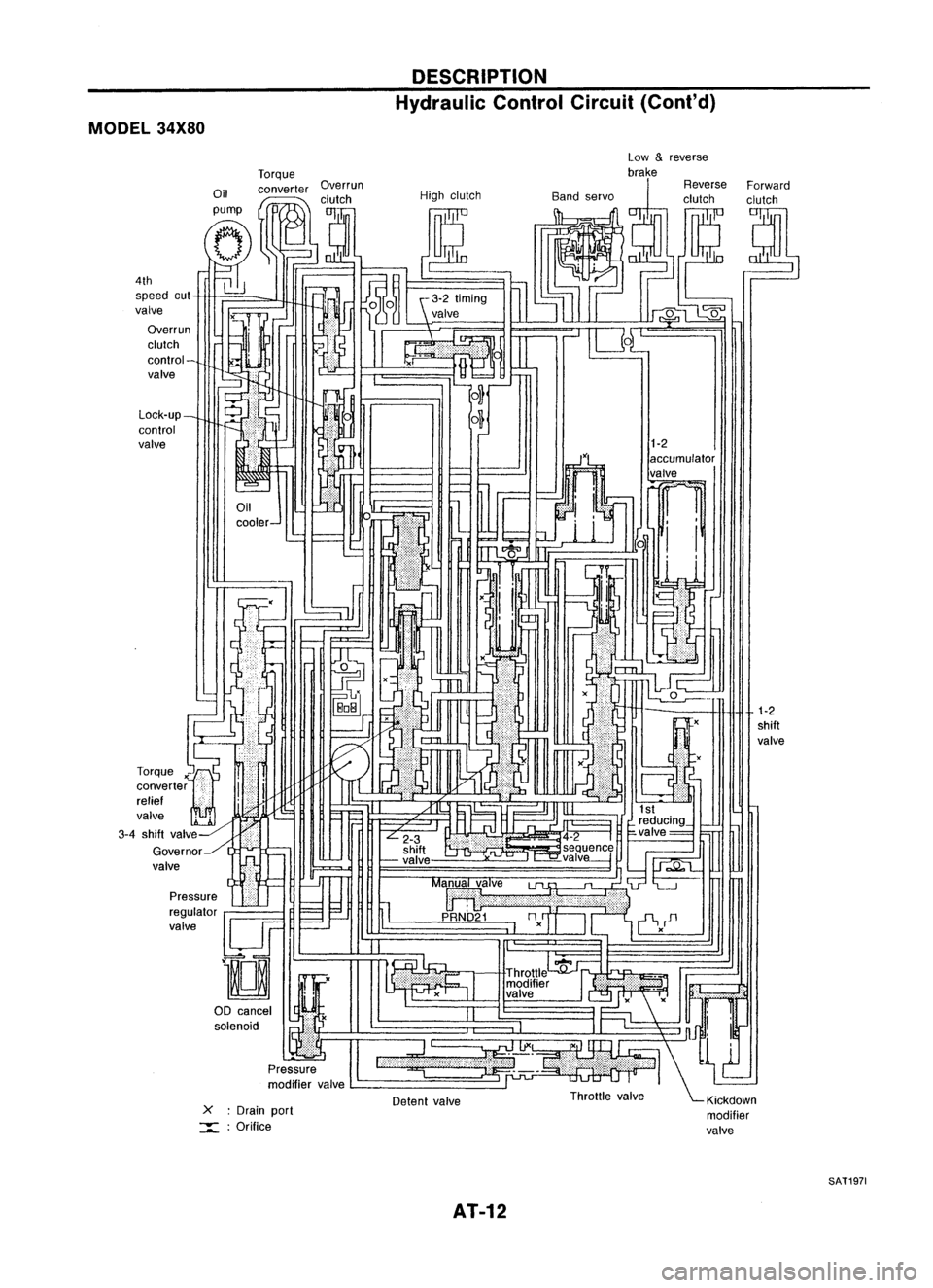
Hydraulic ControlCircuit 10
Shift Mechanism 14
Control System 15
TROUBLE DIAGNOSES 17
Preliminary Check(PriortoRoad Testing) 17
Road Testing 17
Stall Tasting 24
Pressure Testing 26
Wiring Diagram -AT - 28
Electrical Components Inspection 30
ON-VEHICLE SERVICE 31
Control ValveAssembly andAccumulator 31
Throttle WireAdjustment.. 33
Control CableInstallation andAdjustment 35
Governor Valve 36
Inhibitor SwitchAdjustment 37
Differential SideOilSeal Replacement.. 37
REMOVAL ANDINSTALLATION
39
Removal 39
Installation .40MAJOR
OVERHAUL.. 42
All Models 42
Except Model34X81 .44
Model 34X81 45•
Shift Control Components 46
i
Oil Channel 47
Locations ofAdjusting Shims,Needle
Bearings, ThrustWashers andSnap Rings -
Except Model34X81 .48
Locations ofAdjusting Shims,Needle
Bearings, ThrustWashers andSnap Rings -
Model 34X81 .49
DiSASSEMBLy 50
REPAIR FORCOMPONENT PARTS 66
Manual ShaftandThrottle Lever 66
Oil Pump 70
Control ValveAssembly 74
Control ValveUpper Body 86
Control ValveLower Body 90
Reverse Clutch 93
High Clutch 97
Forward ClutchandOverrun Clutch 102
Low &Reverse Brake 108
Rear Internal Gear,Forward ClutchHuband
Overrun ClutchHub 112
Output Shaft,Output Gear,IdlerGear,
Reduction PinionGearandBearing Retainer
- Except Model34X81 116
Output Shaft,IdlerGear, Reduction Pinion
Gear andBearing Retainer -Model 34X81 121
Band Servo Piston Assembly 126
Final Drive -Except Model34X81 131
Final Drive -Model 34X81 135
Page 12 of 1701
DESCRIPTION
Hydraulic ControlCircuit(Cont'd)
MODEL 34X80
1-2
shift
valve
1-2
accumulator
valve
~ 1
i i
xU
::l.
x
-
Detent valve
L-
_
-
cooler- Low
&
reverse
Torque brake
Oil converter Overrun ReverseForward
I
,clutch Highclutch Bandservo clutchclutch
pump
I
tJ
(Jp::-
(T,
tf1
--;::;-;r.]O~
~J
1~
g~ (~ ~~
l]
J~ ~
~iJ -
N
~%~
UL"-'
IU4~1~~
C-1
-!
~frEJ!
1
6 ~, -~
m
~,--J
0
- ILJ
,-O...J
r
ar
r::r=< I'---,
II .(
I'
IJ
,'-
~
,,'
(
-
I -
=-
~tL ',
~H
I~
~ ~M~ ·
F=
f='l .,.11
1-
~I" ~
" ~r'
I
L...---...l
reducing_
L
2-3 .4-2
I
~valve= ~
shift ~seq!!.enc~
~ -valve ,-=-valve---j
h
1J;;;.Q"t....
=--=-.J
II
Ma~alve
lJl.
"~'L--.J
:;;; ~I 11
p
URNb'21
nn
=-.--'
I~
II
'i-V
D
I I -,
." c:
I
Throttle
':fj'~1 .
modifier
If.'
valve .
II
I
1"
";'Jnn!
l...,
:=~-' \~
Throttle valve ~Klckdown
modifier
valve
X
:Drain port
:::::: :Orifice
Pressure
regulator
valve
!lJF
D
00 cancel
I
~Y&
solenoid •
Pressure
modifier valve
Lock-up_
control
valve
4th
speed cut
valve
Overrun
clutch
control-
valve
-=~
I
r
rr=-
LL:
J~
L~
Torque
x'"~
converter
i
i
relief '
valve
2~ '-
3-4 shift valv~-HiliJI
Governor../l ..-
valve
SAT1971
AT-12
Page 15 of 1701
DESCRIPTION
Shift Mechanism (Cont'd)
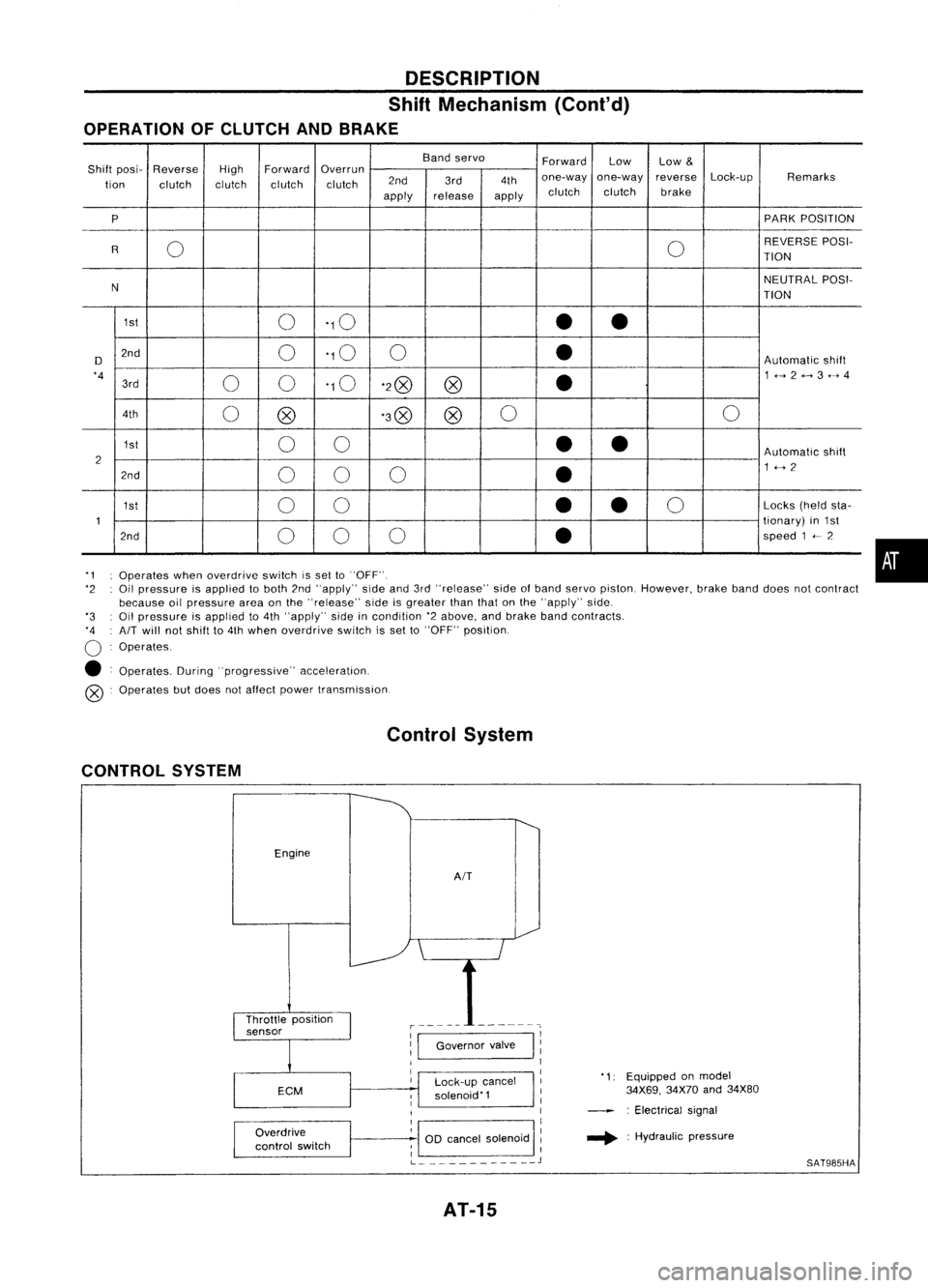
OPERATION OFCLUTCH ANDBRAKE
Bandservo
ForwardLow
Low
&
Shift posi- Reverse
HighForward
Overrun
Lock-upRemarks
tion clutch clutchclutchclutch 2nd
3rd4thone-way
one-way reverse
apply release
applyclutch
clutch brake
P PARK
POSITION
0 0REVERSE
POSI-
R TION
N NEUTRAL
POSI-
TION
1st 0'10
••
D 2nd
0'10
0
•
Automatic
shift
'4 00'10
'2@
@
•
1<-->2<-->3<-->4
3rd
4th 0@ '3@
@0
0
1st 00
••
Automatic
shift
2 1<-->2
2nd 00 0
•
1st 00
•
•
0
Locks
(heldsta-
1 tionary)
in1st
2nd 00 0
•
speed
1
<--
2
'1 Operates whenoverdrive switchissel to"OFF".
'2 Oilpressure isapplied toboth 2nd"apply" sideand3rd"release" sideofband servo piston. However, brakebanddoes notcontract
because oilpressure areaonthe "release" sideisgreater thanthatonthe "apply" side.
'3 Oilpressure isapplied to4th "apply" sideincondition '2above, andbrake bandcontracts.
'4 AIT
will notshift to4th when overdrive switchisset to"OFF" position.
o
Operates.
• Operates. During"progressive" acceleration.
@ Operates butdoes notaffect power transmission.
Control System
CONTROL SYSTEM
Engine
AIT
•
Lock-up cancel
solenoid'1
Overdrive
control switch
1:1
Governor valve
I
11
1
I
1
1
OD cancel solenoid :
; I
L
J
AT-15
'1:
Equipped onmodel
34X69, 34X70and34X80
: Electrical signal
.... :Hydraulic pressure
SAT985HA
Page 26 of 1701
TROUBLEDIAGNOSES
Pressure Testing
• Location ofpressure testport.
• Always replace pressure plugsasthey areself-sealing
bolts.
Test portfor
line pressure governor
pressure
SAT565D
LINEPRESSURE TESTPROCEDURE
1. Check AfTand engine fluidlevels. Ifnecessary, addfluid.
2. Drive vehicle forabout 10minutes untilengine oiland ATF
reach operating temperature.
ATF operating temperature:
50 -80°C (122-176°F)
SAT647B
3.Install pressure gaugetoline pressure port.
4. Set parking brakeandblock wheels.
Continue todepress brakepedalfullywhile performing line
pressure testatstall speed.
SAT513G
5.Start engine andmeasure linepressure atidle and stall
speed. Line pressure:
Refer toSOS, AT-166.
JUDGEMENT OFLINE PRESSURE TEST
• Ifline pressure doesnotrise, firstcheck tomake surethat
throttle wireisconnected properly.
1) When linepressure whileidling
is
low atall positions ("D",
"2", "1", "R"and"P"), theproblem maybedue to:
SAT494G •
Wear oninterior ofoil pump
AT-26
Page 27 of 1701
'-)
(
~)o
Front
SAT498GTROUBLE
DIAGNOSES
Pressure Testing(Cont'd)
• Oilleakage ator around oilpump, control valvebody, trans-
mission caseorgovernor
• Sticking pressure regulator valve
• Sticking pressure modifiervalve
2) When linepressure whileidling islow ataparticular
position, checkthefollowing.
• Ifoil leaks ator around low
&
reverse brakecircuit, line
pressure becomes lowin"R" position. Butline pressure is
normal in"P", "D", "2"or"1" position.
3) When linepressure ishigh while idling, pressure regulator
valve mayhave stuck.
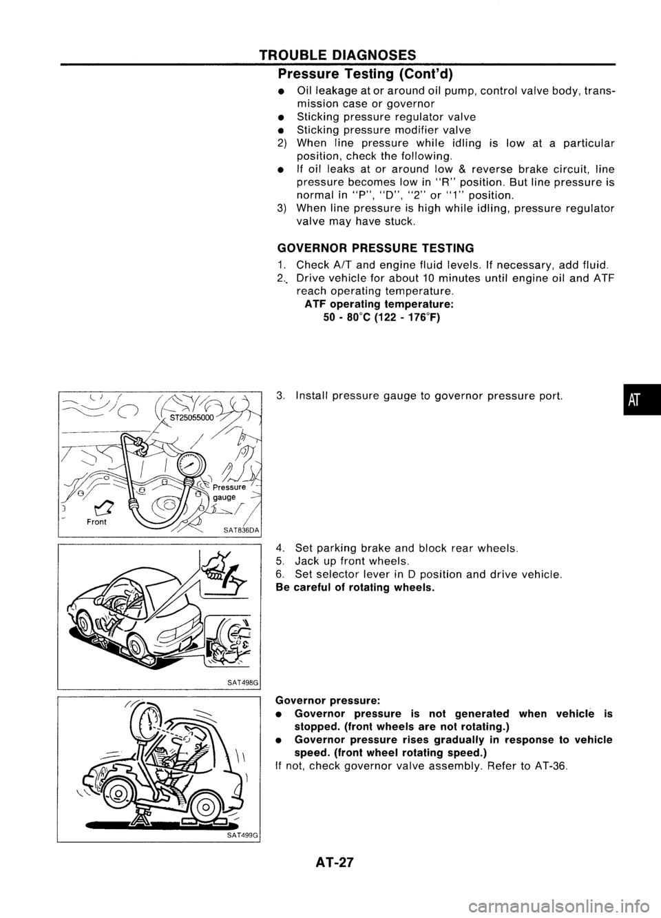
GOVERNOR PRESSURETESTING
1. Check
AIT
and engine fluidlevels. Ifnecessary, addfluid.
2 .. Drive vehicle forabout 10minutes untilengine oiland ATF
reach operating temperature.
ATF operating temperature:
50 -80°C (122-176°F)
3. Install pressure gaugetogovernor pressureport.
4. Set parking brakeandblock rearwheels.
5. Jack upfront wheels.
6. Set selector leverinDposition anddrive vehicle.
Be careful ofrotating wheels.
•
Governor pressure:
• Governor pressureisnot generated whenvehicle is
stopped. (frontwheels arenotrotating.)
• Governor pressurerisesgradually inresponse tovehicle
speed. (frontwheel rotating speed.)
If not, check governor valveassembly. RefertoAT-36.
AT-27
Page 47 of 1701
MAJOROVERHAUL
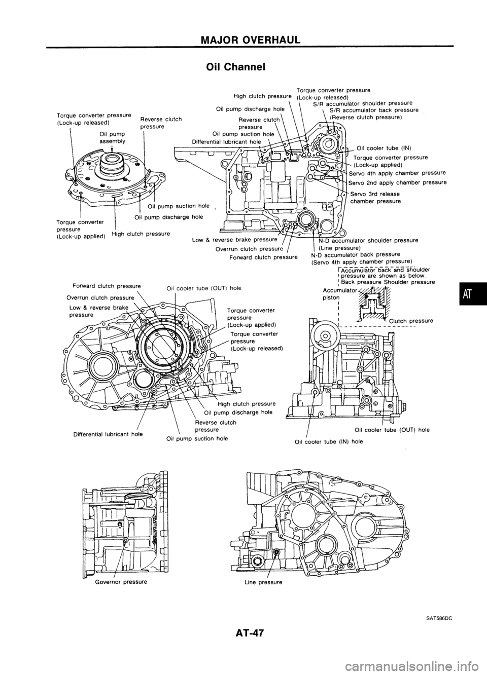
Oil Channel
High clutch pressure
Oilcooler tube(OUT) hole
•
Oil
cooler tube
(IN)
Torque converter pressure
(Lock-up applied)
" Servo
4th
apply chamber pressure
Servo 2ndapply chamber pressure
• Servo 3rdrelease
chamber pressure
Torque
converter pressure
(Lock-up released)
SIR accumulator shoulderpressure
SIR accumulator backpressure
(Reverse clutchpressure)
Oil cooler tube
(IN)
hole
Torque
converter
pressure (Lock-up applied)
Torque converter
pressure (Lock-up released)
reverse
brakepressure
Overrun clutchpressure
Forward clutchpressure
High
clutch pressure
Reverse clutch
pressure
Oil pump suction hole
Differential lubricanthole
High clutch pressure
Oil pump discharge hole
Reverse clutch
pressure
Oil pump suction hole
Reverse
clutch
pressure
Low
&
Oil
pump suction hole
Oil pump discharge hole
Forward clutchpressure
Overrun clutchpressure
Low
&
reverse brake
pressure
Torque
converter pressure
(Lock-up released)
Torque converter
pressure (Lock-up applied)
Governor pressure
Linepressure
SAT586DC
AT-47
Page 51 of 1701
SAT620EDISASSEMBL
Y
5. Set manual shaftto"P" position.
6. Remove inhibitorswitch.
Waste material
Oil
pan
SAT013D
7.
Remove oilpan andoilpan gasket.
• Donot reuse oilpan bolts.
8. Check foreign materials inoil pan tohelp determine cause•
of malfunction. Ifthe fluid isvery dark, smells burned, or
contains foreignparticles, thefrictional material(clutches,
band) mayneed replacement. Atacky filmthat willnotwipe
clean indicates varnishbuildup.Varnish cancause valves,
servo andclutches tostick andcaninhibit pumppressure.
• Iffrictional materialisdetected, replaceradiator afterrepair
of AlT. Refer toLC section ("Radiator", "ENGINECOOLING
SYSTEM").
SAT711D
9.
Remove controlvalveassembly according tothe following
procedures.
a. Remove controlvalveassembly mountingbolts@,
CID,
@
and @.
AT-51
Page 167 of 1701
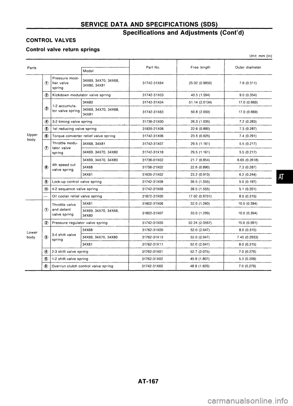
SERVICEDATAANDSPECIFICATIONS (SOS)
Specifications andAdjustments (Cont'd)
CONTROL VALVES
Control valvereturn springs
Unit:
mm
(in)
Parts Part
No. Freelength
Outerdiameter
Model
Pressure modi-
34X69,34X70, 34X68,
d)
liervalve 31742-31X642502(0.9850) 79(0.311)
spring 34X80,
34X81
@)
Kickdown
modulator valvespring 31742-31X03 40.5(1.594) 9.0(0.354)
34X80 31742-31X0451.14(2.0134) 17.0(0.669)
@
1-2
accumula-
tor valve spring 34X69,
34X70,34X68,
34X81 31742-31X63
50.8(2000) 17.0(0.669)
@
3-2timing valvespring 31736-21
XOO 26.3(1.035) 7.2(0.283)
~ 1st
reducing valvespring 31835-21X0822.6(0.890) 7.3(0.287)
Upper
@
Torque converter reliefvalve spring 31742-31X06 23.5(0.925) 7.4(0.291)
body Throttlemodu-
34X68,34X81
31742-31X07 29.5
(1.161)
5.5(0.217)
(J)
lator valve
spring 34X69,
34X70, 34X80 31742-31X18 29.5(1161)
5.5(0.217)
34X69, 34X70, 34X80 31736-01X02 21.7(0.854) 6.65(0.2618)
@
4th
speed cut
34X68 31756-21X0222.6(0.890)
7.3(0.287)
valve spring
34X81 31835-21X0223.2(0913) 6.2(0.244)
@
Lock-up
controlvalvespring 31742-31X08
39.5(1.555) 50(0.197)
@
4-2sequence valvespring 31742-31X0939.5(1.555) 51(0.201)
-
Oilcooler reliefvalve spring 31872-31XOO17.02(0.6701) 8.0(0.315)
Throttle valve 34X81
31802-31X06 32.0(1.260) 10.0(0.394)
d)
anddetent
34X69,34X70, 34X68,
valve spring
34X80 31802-31X07
33.0
(1.299)
10.0(0.394)
(2)
Pressure regulatorvalvespring 31742-31XOO 5224(2.0567) 15.0(0.591)
Lower 34X68
31762-31XOO
52.0(2.047)
8.0(0.315)
body
@
3-4
shift valve
34X69,34X70,34X80 31762-31X13 52.0(2.047) 7.45(0.2933)
spring
34X81 31762-31X1152.0(2.047) 80(0.315)
@
2-3shift valve spring 31762-31X0152.7(2.075) 7.0(0.276)
cID
1-2
shift valve spring 31762-31X0245.9(1.807) 5.3(0.209)
@
Overrun clutchcontrol valvespring 31742-31X60 48.9
(1.925) 7.0(0.276)
AT-167
•