1995 NISSAN ALMERA N15 engine overheat
[x] Cancel search: engine overheatPage 17 of 1701

Fluidleakage TROUBLE
DIAGNOSES
Preliminary Check(PriortoRoad Testing)
AIT FLUID CHECK
Fluid leakage check
1. Clean areasuspected ofleaking, -for example, mating
surface ofconverter housingandtransmission case.
2. Start engine, applyfootbrake, placeselector leverin"0"
position andwait afew minutes.
3. Stop engine.
4. Check forfresh leakage.
SAT288G
Fluidcondition check
Fluid levelcheck -Refer toMA section (CHASSIS AND
BODY MAINTENANCE).
Fluid
color
Oark orblack withburned odor
Milky pink
Varnished fluid,lighttodark brown
and tacky Suspected
problem
Wear offrictional material
Water contamination
- Road water entering through
filler tubeorbreather
Oxidation
- Over orunder filling
- Overheating
•
Road Testing
Perform roadtests using "Symptom" chart.Refertopage
AT-20.
"P"
POSITION
1. Place selector leverin"P" position andstart engine. Stop
engine andrepeat theprocedure inall positions, including
neutral position.
2. Stop vehicle onaslight upgrade andplace selector leverin
"P" position. Releaseparkingbraketomake surevehicle
remains locked.
"R"
POSITION
1. Manually moveselector leverfrom"P"to"R", andnote
shift quality.
2. Drive vehicle inreverse longenough todetect slippage or
other abnormalities.
"N"
POSITION
1. Manually moveselector leverfrom"R"and"0"to"N" and
note shift quality.
2. Release parkingbrakewithselector leverin"N" position.
Lightly depress accelerator pedaltomake surevehicle
does notmove. (When vehicle isnew orsoon afterclutches
have been replaced, vehiclemaymove slightly. Thisisnot
a problem.)
AT-17
Page 765 of 1701

ON-BOARDDIAGNOSTIC SYSTEMDESCRIPTION @KJ
Malfunction Indicatorlamp(Mil)(Cont'd)
DIAGNOSTIC TESTMODE I-BULB CHECK
In this mode, theMALFUNCTION INDICATORLAMPonthe instrument panelshould stayON.Ifitremains
OFF, check thebulb. Refer toEL section ("WARNING LAMPSANDCHIME") orsee EC-223.
DIAGNOSTIC TESTMODE I-MALFUNCTION WARNING
MALFUNCTION INDICATORLAMP
ON
OFF Condition
Engine coolant temperature sensorcircuitmalfunction oroverheating isdetected, or
the ECM's CPUismalfunctioning.
No malfunction.
• These Diagnostic TroubleCodeNumbers areclarified inDiagnostic TestMode II(SELF-DIAGNOS-
TIC RESULTS).
DIAGNOSTIC TESTMODE II-SELF-DIAGNOSTIC RESULTS
In this mode, adiagnostic troublecodeisindicated bythe number ofblinks ofthe MALFUNCTION INDI-
CATOR LAMPasshown below.
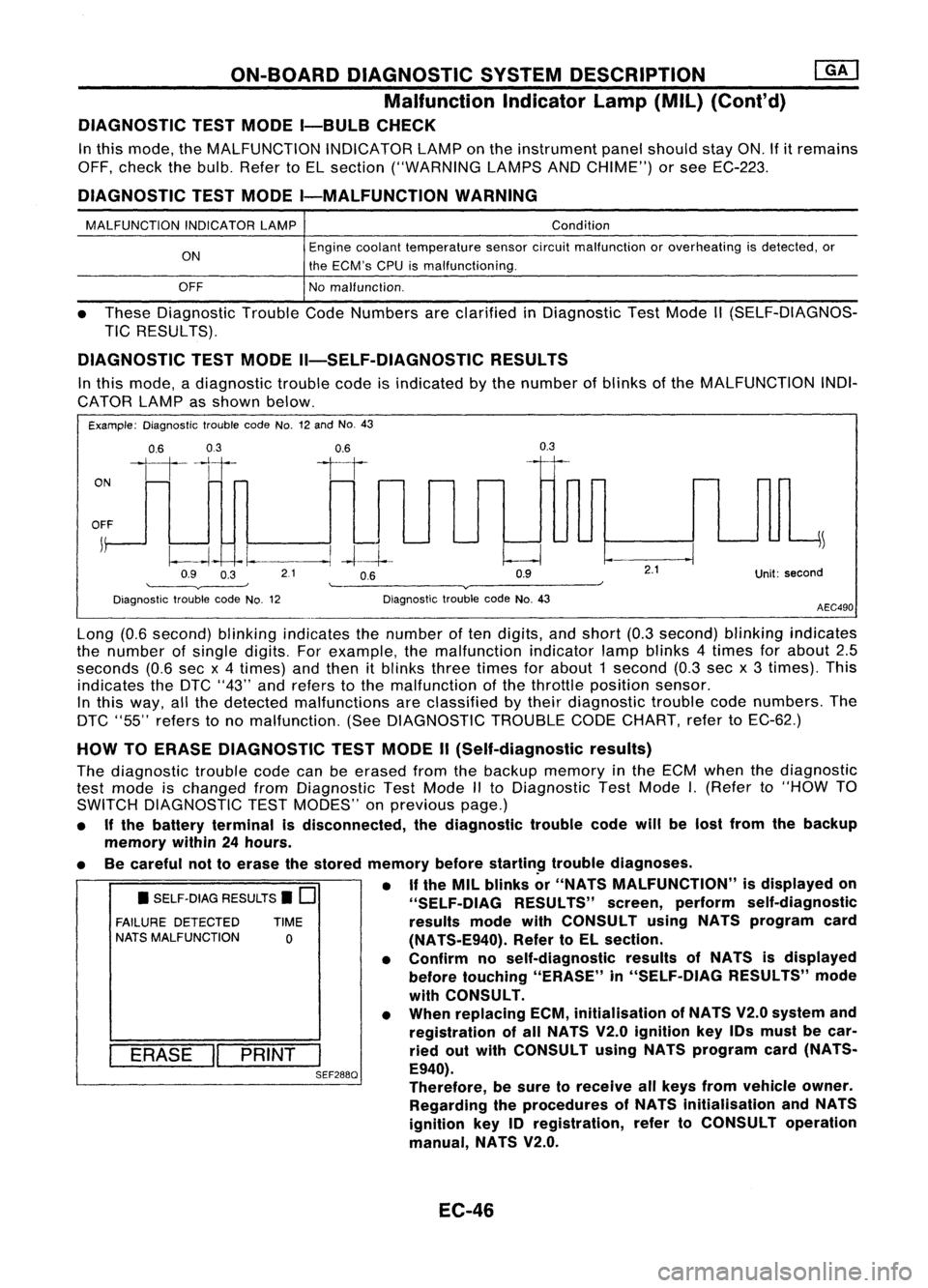
Example: Diagnostic troublecodeNo.12and No.43
ON
0.6
03
111-'1
0.6
II
0.3
OFF
j
~
~~ -I.
--.1
-4--1--
Q9 O~ 21 OB Q9
'--------v----' '--------v------~
Diagnostic troublecodeNo.12 DiagnostictroublecodeNo.43
2.1
Unit:second
AEC490
• SELF-DIAG RESULTS.
0
FAILURE DETECTED TIME
NATS MALFUNCTION
0
I
ERASE
II
PRINT
I
SEF288Q
Long
(0.6second) blinkingindicates thenumber often digits, andshort (0.3second) blinkingindicates
the number ofsingle digits. Forexample, themalfunction indicatorlampblinks 4times forabout 2.5
seconds (0.6secx4 times) andthen itblinks threetimes forabout 1second (0.3secx3 times). This
indicates theDTC "43" andrefers tothe malfunction ofthe throttle position sensor.
In this way, allthe detected malfunctions areclassified bytheir diagnostic troublecodenumbers. The
DTC "55" refers tono malfunction. (SeeDIAGNOSTIC TROUBLECODECHART, refertoEC-62.)
HOW TOERASE DIAGNOSTIC TESTMODE II(Self-diagnostic results)
The diagnostic troublecodecanbeerased fromthebackup memory inthe ECM when thediagnostic
test mode ischanged fromDiagnostic TestMode IIto Diagnostic TestMode
I.
(Refer to"HOW TO
SWITCH DIAGNOSTIC TESTMODES" onprevious page.)
• Ifthe battery terminal isdisconnected, thediagnostic troublecodewillbelost from thebackup
memory within24hours.
• Becareful nottoerase thestored memory before
startin~
troublediagnoses.
• If
the MIL blinks or"NATS MALFUNCTION" isdisplayed on
"SELF-OIAG RESULTS"screen,perform self-diagnostic
results modewithCONSULT usingNATS program card
(NATS-E940). RefertoEL section.
• Confirm noself-diagnostic resultsofNATS isdisplayed
before touching "ERASE" in"SELF-DIAG RESULTS"mode
with CONSULT.
• When replacing ECM,initialisation ofNATS V2.0system and
registration ofall NATS V2.0ignition key10smust becar-
ried outwith CONSULT usingNATS program card(NATS-
E940).
Therefore, besure toreceive allkeys from vehicle owner.
Regarding theprocedures ofNATS initialisation andNATS
ignition key10registration, refertoCONSULT operation
manual, NATS V2.0.
EC-46
Page 781 of 1701

TROUBLEDIAGNOSIS -General Description
Diagnostic TroubleCode(DTC) Chart
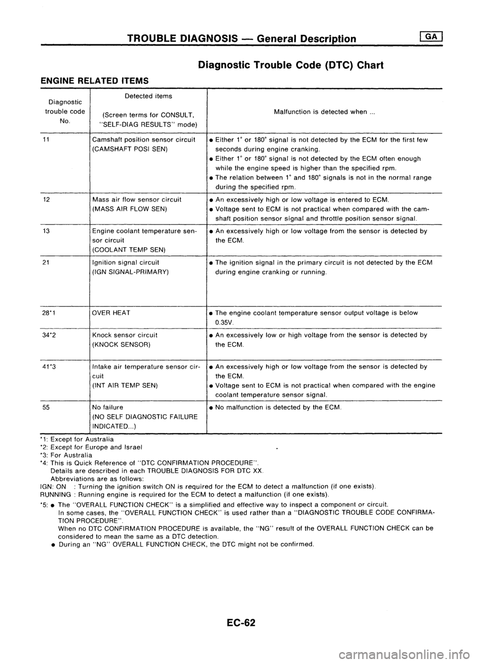
ENGINE RELATED ITEMS
Detected items
Diagnostic
trouble code
(ScreentermsforCONSULT, Malfunction
isdetected when...
No. "SELF-DIAG RESULTS"mode)
11 Camshaftpositionsensorcircuit
•Either
l'
or 180' signal isnot detected bythe ECM forthe first few
(CAMSHAFT POSISEN)
secondsduringengine cranking .
• Either
l'
or 180' signal isnot detected bythe ECM often enough
while theengine speedishigher thanthespecified rpm.
• The relation between
l'
and 180' signals isnot inthe normal range
during thespecified rpm.
12 Massairflow sensor circuit
•An excessively highorlow voltage isentered toECM.
(MASS AIRFLOW SEN) •Voltage senttoECM isnot practical whencompared withthecam-
shaft position sensorsignalandthrottle position sensorsignal.
13 Enginecoolant temperature sen-•An excessively highorlow voltage fromthesensor isdetected by
sor circuit
theECM.
(COOLANT TEMPSEN)
21 Ignitionsignalcircuit
•The ignition signalinthe primary circuitisnot detected bythe ECM
(IGN SIGNAL-PRIMARY)
duringengine cranking orrunning .
28*1 OVERHEAT •The engine coolant temperature sensoroutputvoltage isbelow
0.35V .
34"2 Knocksensor circuit •An excessively loworhigh voltage fromthesensor isdetected by
(KNOCK SENSOR) theECM.
41 *3 Intakeairtemperature sensorcir-•An excessively highorlow voltage fromthesensor isdetected by
cuit theECM.
(INT AIRTEMP SEN) •Voltage senttoECM isnot practical whencompared withtheengine
coolant temperature sensorsignal.
55
Nofailure •No malfunction isdetected bythe ECM.
(NO SELF DIAGNOSTIC FAILURE
INDICATED ...)
"1: Except forAustralia
*2: Except forEurope andIsrael
"3: For Australia
*4: This isQuick Reference of"DTC CONFIRMATION PROCEDURE".
Details aredescribed ineach TROUBLE DIAGNOSIS FORDTCXX
Abbreviations areasfollows:
IGN: ON :Turning theignition switchONisrequired forthe ECM todetect amalfunction (ifone exists).
RUNNING: Runningengineisrequired forthe ECM todetect amalfunction (ifone exists).
*5: •The "OVERALL FUNCTIONCHECK"isasimplified andeffective waytoinspect acomponent orcircuit.
In some cases, the"OVERALL FUNCTIONCHECK"isused rather thana"DIAGNOSTIC TROUBLECODECONFIRMA-
TION PROCEDURE".
When noDTC CONFIRMATION PROCEDUREisavailable, the"NG" result ofthe OVERALL FUNCTION CHECKcanbe
considered tomean thesame asaDTC detection .
• During an"NG" OVERALL FUNCTION CHECK,theDTC might notbeconfirmed.
EC-62
Page 1429 of 1701

TROUBLEDIAGNOSES
Trouble Diagnoses forAbnormal Pressure
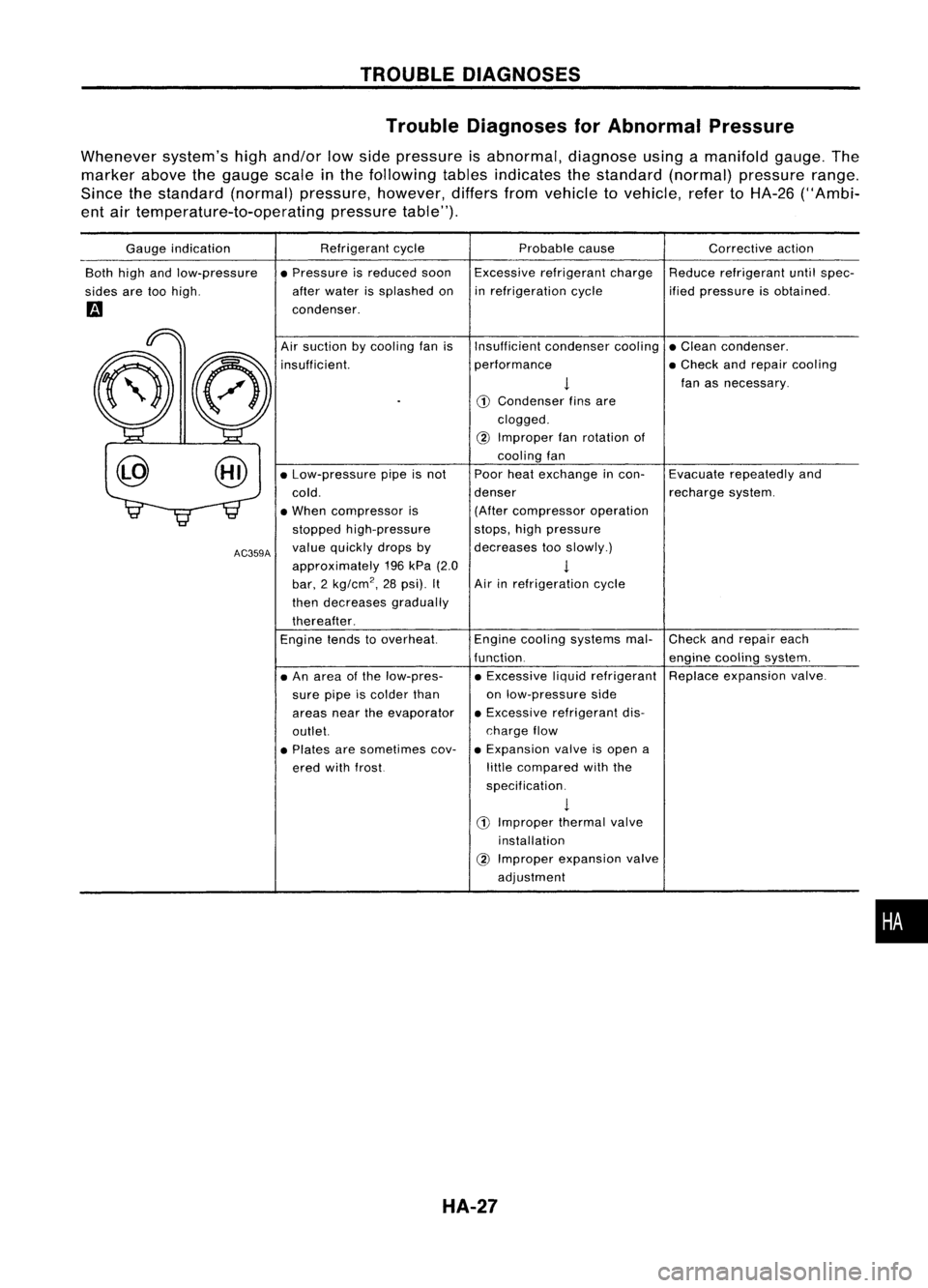
Whenever system'shighand/or lowside pressure isabnormal, diagnoseusingamanifold gauge.The
marker abovethegauge scale
in
the following tablesindicates thestandard (normal)pressure range.
Since thestandard (normal)pressure, however,differsfromvehicle tovehicle, refertoHA-26 ("Ambi-
ent airtemperature-to-operating pressuretable").
Gauge indication
Both highandlow-pressure
sides aretoohigh.
m
Refrigerant
cycle
• Pressure isreduced soon
after water issplashed on
condenser. Probable
cause
Excessive refrigerant charge
in refrigeration cycle Corrective
action
Reduce refrigerant untilspec-
ified pressure isobtained.
•
Check
andrepair each
engine cooling system.
Replace expansion valve.
Evacuate
repeatedly and
recharge system.
Insufficient
condensercooling•Clean condenser.
performance •Check andrepair cooling
!
fanasnecessary.
CD
Condenser finsare
clogged.
@
Improper fanrotation of
cooling fan
Poor heatexchange incon-
denser (After compressor operation
stops, highpressure
decreases tooslowly.)
1
Air inrefrigeration cycle
Engine cooling systems mal-
function. • Excessive liquidrefrigerant
on low-pressure side
• Excessive refrigerant dis-
charge flow
• Expansion valveisopen a
little compared withthe
specification.
1
CD
Improper thermalvalve
installation
@
Improper expansion valve
adjustment
Air
suction bycooling fanis
insufficient.
• An area ofthe low-pres-
sure pipeiscolder than
areas neartheevaporator
outlet.
• Plates aresometimes cov-
ered withfrost.
•
Low-pressure pipeisnot
cold.
• When compressor is
stopped high-pressure
value quickly dropsby
approximately 196kPa (2.0
bar, 2
kg/cm
2,
28psi). It
then decreases gradually
thereafter.
Engine tendstooverheat.
AC359A
HA-27
Page 1506 of 1701
![NISSAN ALMERA N15 1995 Service Manual
MAX,
MIN.
ENGINE
MAINTENANCE [QK]
Changing EngineCoolant (Cont'd)
7. Warm upengine untilcooling fanoperates, thenrace
engine 2or 3times under no-load.
8. Stop engine andwait until itcools down NISSAN ALMERA N15 1995 Service Manual
MAX,
MIN.
ENGINE
MAINTENANCE [QK]
Changing EngineCoolant (Cont'd)
7. Warm upengine untilcooling fanoperates, thenrace
engine 2or 3times under no-load.
8. Stop engine andwait until itcools down](/manual-img/5/57349/w960_57349-1505.png)
MAX,
MIN.
ENGINE
MAINTENANCE [QK]
Changing EngineCoolant (Cont'd)
7. Warm upengine untilcooling fanoperates, thenrace
engine 2or 3times under no-load.
8. Stop engine andwait until itcools down.
9. Drain water.
10. Repeat steps2through 9until clear water begins todrain
from radiator.
-REFILLING ENGINECOOLANT-
11. Install reservoir tank,radiator drainplug,cylinder block
drain plugandairrelief plug
@.
• Apply sealant tothe thread ofcylinder blockdrainplug.
toJ:
34-44 N.m (3.5-4.5 kg-m, 25-33 ft-Ib)
12. Fill radiator withcoolant untilcoolant spillsfromtheair
relief plug
@
hole, theninstall airrelief plug
@.
13. Fill radiator andreservoir tankwithcoolant uptospecified
level andinstall radiator cap.
Air relief plug:
~: 7-8 N.m (0.7-0.8 kg-m, 61-69 in-Ib)
For coolant mixture ratio,refertoMA-16.
Coolant capacity (Withreservoir tank):
Unit:f(Imp qt)
With heater
Withoutheater
M/T 5.9(5-1/4) 5.6(4-7/8)
AIT 6.4(5-5/8) 6.1(5-3/8)
Reservoir tankcapacity (forMAX level):
o.n
(5/8Impqt)
Pour coolant through coolantfillerneckslowly toallow airin
system toescape.
14. Warm upengine tonormal operating temperature.
15. Run engine at2,500 rpmfor10seconds andreturn toidle
speed.
• Repeat 2or 3times.
Watch coolant temperature gaugesoas not tooverheat the
engine.
SMA4128
MA-20
Page 1517 of 1701
![NISSAN ALMERA N15 1995 Service Manual SLC0538
Water
inlet
Water
outlet ENGINE
MAINTENANCE [][]
Changing EngineCoolant (Cont'd)
14. Warm upengine tonormal operating temperature.
15. Run engine at2,500 rpmfor10seconds andreturn toidle
NISSAN ALMERA N15 1995 Service Manual SLC0538
Water
inlet
Water
outlet ENGINE
MAINTENANCE [][]
Changing EngineCoolant (Cont'd)
14. Warm upengine tonormal operating temperature.
15. Run engine at2,500 rpmfor10seconds andreturn toidle](/manual-img/5/57349/w960_57349-1516.png)
SLC0538
Water
inlet
Water
outlet ENGINE
MAINTENANCE [][]
Changing EngineCoolant (Cont'd)
14. Warm upengine tonormal operating temperature.
15. Run engine at2,500 rpmfor10seconds andreturn toidle
speed .
• Repeat 2or 3times. •
Wat~h coolant temperature gaugesoasnot tooverheat the
i
engme.
16. Stop engine andcool itdown.
• Cool down usingafan toreduce thetime.
17. Refill reservoir tanktoMax linewith coolant.
18. Repeat step15through step17two ormore times.
19. Warm upengine, andcheck forsound ofcoolant flowwhile
running enginefromidleupto4,000 rpmwith heater tem-
perature controlsetatseveral positions betweenCOOLand
HOT.
• Sound maybenoticeable atheater watercock.
20.
If
sound isheard, bleedairfrom cooling systembyrepeat-
ing steps 14through 17until coolant levelnolonger drops.
• Clean excess coolant fromengine.
CAUTION:
When heater unitisremoved orreplaced, refillengine coolant
as shown, removing heaterhoseatfeeding connector on
engine.
Checking CoolingSystem
CHECKING HOSES
Check hosesforimproper attachment andforleaks, cracks,
damage, looseconnections, chafinganddeterioration.
CHECKING RADIATORCAP
Apply pressure toradiator capwith captester tosee ifit is sat-
isfactory.
Radiator caprelief pressure:
Standard 78 -98 kPa
(0.78 -0.98 bar,0.8-1.0 kg/cm
2,
11-14 psi)
limit
59-98 kPa
(0.59 -0.98 bar,0.6-1.0 kg/cm
2,
9-14 psi)
MA-31