Page 14 of 1701

DESCRIPTION
Shift Mechanism
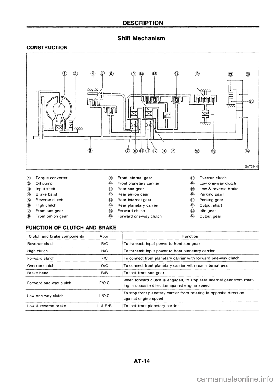
CONSTRUCTION
18
,:-1
SAT214H
ill
Torque converter
@
Oilpump
@
Input shaft
@
Brake band
@
Reverse clutch
@
High clutch
o
Front sungear
@
Front pinion gear
@
Front internal gear
@l
Front planetary carrier
@
Rear sungear
@
Rear pinion gear
@
Rear internal gear
@
Rear planetary carrier
@
Forward clutch
@
Forward one-way clutch
@
Overrun clutch
@
Lowone-way clutch
@
Low
&
reverse brake
@
Parking pawl
@
Parking gear
@
Output shaft
@
Idlegear
@
Output gear
FUNCTION OFCLUTCH ANDBRAKE
Glutch andbrake components Abbr. Function
Reverse clutch
RIG
To
transmit inputpower tofront sungear
High clutch
HIG
To
transmit inputpower tofront planetary carrier
Forward clutch
FIG
To
connect frontplanetary carrierwithforward one-way clutch
Overrun clutch
OIG
To
connect frontplanetary carrierwithrearinternal gear
Brake band BIBTo
lock front sungear
Forward one-way clutch
F/O.G
When
forward clutchisengaged, tostop rearinternai gearfrom rotat-
ing inopposite direction againstenginespeed
Low one-way clutch LlO.GTo
stop front planetary carrierfromrotating inopposite direction
against enginespeed
Low
&
reverse brake L
&
RIB To
lock front planetary carrier
AT-14
Page 17 of 1701

Fluidleakage TROUBLE
DIAGNOSES
Preliminary Check(PriortoRoad Testing)
AIT FLUID CHECK
Fluid leakage check
1. Clean areasuspected ofleaking, -for example, mating
surface ofconverter housingandtransmission case.
2. Start engine, applyfootbrake, placeselector leverin"0"
position andwait afew minutes.
3. Stop engine.
4. Check forfresh leakage.
SAT288G
Fluidcondition check
Fluid levelcheck -Refer toMA section (CHASSIS AND
BODY MAINTENANCE).
Fluid
color
Oark orblack withburned odor
Milky pink
Varnished fluid,lighttodark brown
and tacky Suspected
problem
Wear offrictional material
Water contamination
- Road water entering through
filler tubeorbreather
Oxidation
- Over orunder filling
- Overheating
•
Road Testing
Perform roadtests using "Symptom" chart.Refertopage
AT-20.
"P"
POSITION
1. Place selector leverin"P" position andstart engine. Stop
engine andrepeat theprocedure inall positions, including
neutral position.
2. Stop vehicle onaslight upgrade andplace selector leverin
"P" position. Releaseparkingbraketomake surevehicle
remains locked.
"R"
POSITION
1. Manually moveselector leverfrom"P"to"R", andnote
shift quality.
2. Drive vehicle inreverse longenough todetect slippage or
other abnormalities.
"N"
POSITION
1. Manually moveselector leverfrom"R"and"0"to"N" and
note shift quality.
2. Release parkingbrakewithselector leverin"N" position.
Lightly depress accelerator pedaltomake surevehicle
does notmove. (When vehicle isnew orsoon afterclutches
have been replaced, vehiclemaymove slightly. Thisisnot
a problem.)
AT-17
Page 24 of 1701
TROUBLEDIAGNOSES
Stall Tasting
STALL TESTPROCEDURE
1. Check
AIT
and engine fluidlevels. Ifnecessary, addfluid.
2. Drive vehicle forabout 10minutes untilengine oiland ATF
reach operating temperature.
ATF operating temperature:
50 -80
0
e (122-176°F)
SAT6478
3.Set parking brakeandblock wheels.
4. Install atachometer whereitcan beseen bydriver during
test.
SAT513G 5.
~ ~ID
•
~c;>
SAT7678
Start
engine, applyfootbrake, andplace selector leverin
"0"
position.
6. Accelerate towide-open throttlegradually whileapplying
foot brake.
7. Quickly notetheengine stallrevolution andimmediately
release throttle.
• During test,never holdthrottle wide-open formore than5
seconds. Stall revolution .standard:
Refer toSDS, AT-166.
SAT514G
8.Move selector leverto"N" position.
9. Cool offATF.
• Run engine atidle foratleast oneminute.
10. Repeat steps5through 9with selector leverin"2", "1"and
"R
n
positions.
SAT7718 AT-24
Page 26 of 1701
TROUBLEDIAGNOSES
Pressure Testing
• Location ofpressure testport.
• Always replace pressure plugsasthey areself-sealing
bolts.
Test portfor
line pressure governor
pressure
SAT565D
LINEPRESSURE TESTPROCEDURE
1. Check AfTand engine fluidlevels. Ifnecessary, addfluid.
2. Drive vehicle forabout 10minutes untilengine oiland ATF
reach operating temperature.
ATF operating temperature:
50 -80°C (122-176°F)
SAT647B
3.Install pressure gaugetoline pressure port.
4. Set parking brakeandblock wheels.
Continue todepress brakepedalfullywhile performing line
pressure testatstall speed.
SAT513G
5.Start engine andmeasure linepressure atidle and stall
speed. Line pressure:
Refer toSOS, AT-166.
JUDGEMENT OFLINE PRESSURE TEST
• Ifline pressure doesnotrise, firstcheck tomake surethat
throttle wireisconnected properly.
1) When linepressure whileidling
is
low atall positions ("D",
"2", "1", "R"and"P"), theproblem maybedue to:
SAT494G •
Wear oninterior ofoil pump
AT-26
Page 27 of 1701

'-)
(
~)o
Front
SAT498GTROUBLE
DIAGNOSES
Pressure Testing(Cont'd)
• Oilleakage ator around oilpump, control valvebody, trans-
mission caseorgovernor
• Sticking pressure regulator valve
• Sticking pressure modifiervalve
2) When linepressure whileidling islow ataparticular
position, checkthefollowing.
• Ifoil leaks ator around low
&
reverse brakecircuit, line
pressure becomes lowin"R" position. Butline pressure is
normal in"P", "D", "2"or"1" position.
3) When linepressure ishigh while idling, pressure regulator
valve mayhave stuck.
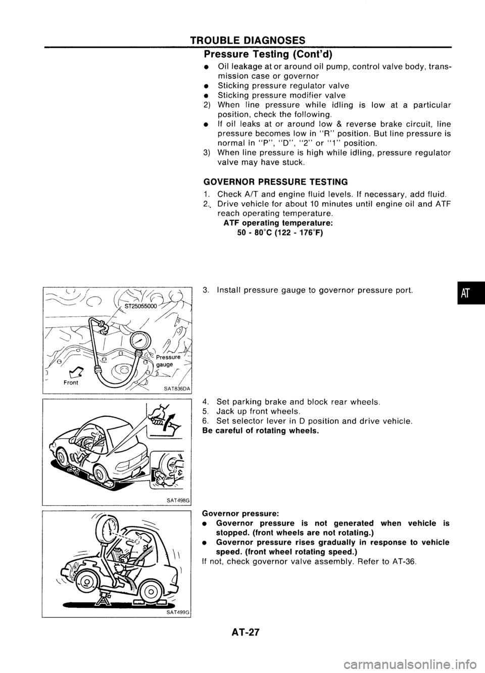
GOVERNOR PRESSURETESTING
1. Check
AIT
and engine fluidlevels. Ifnecessary, addfluid.
2 .. Drive vehicle forabout 10minutes untilengine oiland ATF
reach operating temperature.
ATF operating temperature:
50 -80°C (122-176°F)
3. Install pressure gaugetogovernor pressureport.
4. Set parking brakeandblock rearwheels.
5. Jack upfront wheels.
6. Set selector leverinDposition anddrive vehicle.
Be careful ofrotating wheels.
•
Governor pressure:
• Governor pressureisnot generated whenvehicle is
stopped. (frontwheels arenotrotating.)
• Governor pressurerisesgradually inresponse tovehicle
speed. (frontwheel rotating speed.)
If not, check governor valveassembly. RefertoAT-36.
AT-27
Page 41 of 1701
Boltlength
'T'
mm (in)
55 (2.17)
50 (1.97)
65 (2.56)
25 (0.98)
40 (1.57)
Tightening
torque
N'm (kg-m, ft-Ib)
70 -79 (7.1 -8.1,51 -59)
70 -79 (7.1 -8.1, 51-59)
70 -79 (7.1 -8.1,51 -59)
30 -40 (3.1 -4.1, 22-30)
30 -40 (3.1 -4.1, 22-30)
CD
@
@
@
@
Bolt
No.
• Reinstall anypart removed.
• Adjust throttle wireandcontrol cable.Referto"ON-VEHI-
CLE SERVICE", AT-33,35.
•. Check inhibitor switch.Referto"Electrical Components
Inspection", AT-3D.
• Refill transaxle withATFandcheck fluidlevel, AT-17.
• Move selector leverthrough allpositions tobe sure that
transaxle operatescorrectly. Withparking brakeapplied,
idle engine. Moreselector leverthrough "N"to"D", to"2",
to "1" and "R". Aslight shock should befelt through the
hand gripping theselector eachtimethetransaxle is
shifted. •
• Perform roadtest-Refer to"ROAD TESTING", AT-17.
i
REMOVAL
ANDINSTAllATION
Installation (Cont'd)
SR engine models
SAT638A
SAT558DA
AIT
toengine
@
Engine to
AIT
AT-41
Page 271 of 1701

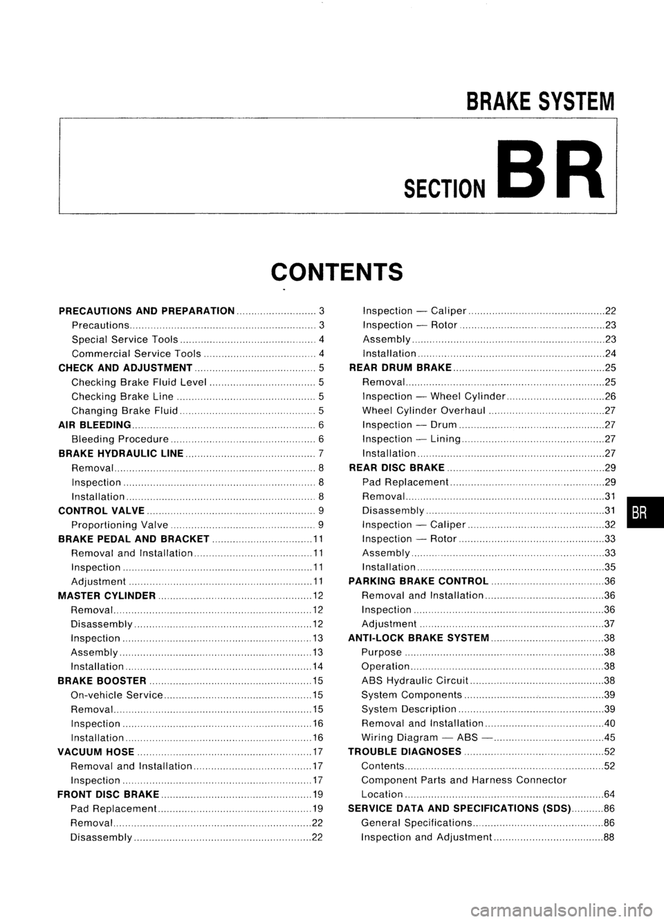
BRAKESYSTEM
SECTION
CONTENTS BR
PRECAUTIONS ANDPREPARATION
3
Precautions 3
Special Service Tools 4
Commercial ServiceTools 4
CHECK ANDADJUSTMENT 5
Checking BrakeFluidLevel 5
Checking BrakeLine 5
Changing BrakeFluid 5
AIR
BLEEDING 6
Bleeding Procedure 6
BRAKE HYDRAULIC LINE 7
Removal 8
Inspection 8
Installation 8
CONTROL VALVE 9
Proportioning Valve 9
BRAKE PEDALANDBRACKET 11
Removal andInstallation 11
Inspection 11
Adjustment 11
MASTER CYLINDER 12
Removal 12
Disassembly 12
Inspection 13
Assembly 13
Installation 14
BRAKE BOOSTER 15
On-vehicle Service 15
Removal 15
Inspection 16
Installation 16
VACUUM HOSE 17
Removal andInstallation 17
Inspection 17
FRONT DISCBRAKE 19
Pad Replacement.. 19
Removal 22
Disassembly 22Inspection
-Caliper 22
Inspection -Rotor 23
Assembly '".23
Installation 24
REAR DRUM BRAKE 25
Removal 25
Inspection -Wheel Cylinder 26
Wheel Cylinder Overhaul 27
Inspection -Drum 27
Inspection -Lining 27
Installation 27
REAR DISCBRAKE 29
Pad Replacement 29
~~s:~::~'~I~':::::::::::'::: ::.::::::::.::::::.::::::::::.::::::.::::::::~~ •••
Inspection -Caliper 32
Inspection -Rotor 33
Assembly 33
Installation 35
PARKING BRAKECONTROL 36
Removal andInstallation 36
Inspection 36
Adjustment ." 37
ANTI-LOCK BRAKESYSTEM 38
Purpose 38
Operation 38
ABS Hydraulic Circuit 38
System Components 39
System Description 39
Removal andInstallation .40
Wiring Diagram -ABS - .45
TROUBLE DIAGNOSES
52
Contents 52
Component PartsandHarness Connector
Location 64
SERVICE DATAANDSPECIFICATIONS (SDS)86
General Specifications 86
Inspection andAdjustment 88
Page 275 of 1701

CHECKANDADJUSTMENT
OK
MINMax.
line
Min. line
SBR418C
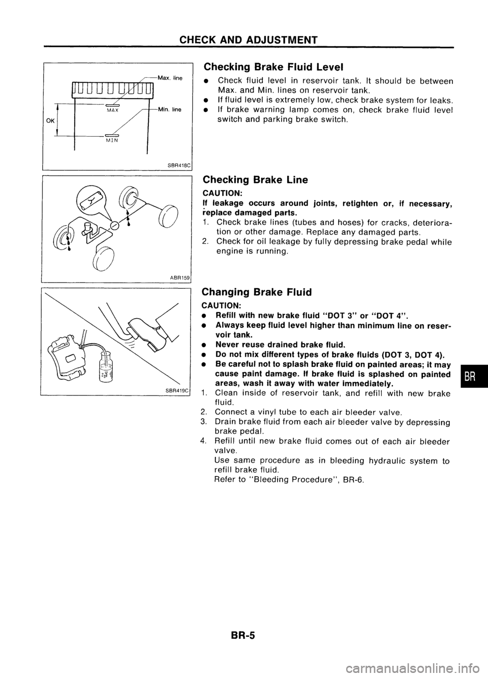
Checking
BrakeFluidLevel
• Check fluidlevel inreservoir tank.Itshould bebetween
Max. andMin. lines onreservoir tank.
• Iffluid level isextremely low,check brakesystem forleaks.
• Ifbrake warning lampcomes on,check brakefluidlevel
switch andparking brakeswitch.
ABR159
SBR419C
Checking
BrakeLine
CAUTION: If leakage occursaround joints,retighten or,ifnecessary,
replace damaged parts.
1. Check brakelines(tubes andhoses) forcracks, deteriora-
tion orother damage. Replaceanydamaged parts.
2. Check foroilleakage byfully depressing brakepedalwhile
engine isrunning.
Changing BrakeFluid
CAUTION:
• Refill withnewbrake fluid"DOT 3"or"DOT 4".
• Always keepfluidlevel higher thanminimum lineonreser-
voir tank.
• Never reusedrained brakefluid.
• Donot mix different typesofbrake fluids(DOT3,DOT 4).
• Becareful nottosplash brakefluidonpainted areas;itmay •
cause paintdamage. Ifbrake fluidissplashed onpainted :•
areas, washitaway withwater immediately.
1. Clean inside ofreservoir tank,andrefill withnewbrake
fluid.
2. Connect avinyl tubetoeach airbleeder valve.
3. Drain brake fluidfrom each airbleeder valvebydepressing
brake pedal.
4. Refill untilnewbrake fluidcomes outofeach airbleeder
valve.
Use same procedure asinbleeding hydraulic systemto
refill brake fluid.
Refer to"Bleeding Procedure", BR-6.
BR-5