1995 NISSAN ALMERA N15 Plugs
[x] Cancel search: PlugsPage 7 of 1701

PREPARATIONANDPRECAUTIONS
Service Notice
Supplemental RestraintSystem(SRS)"AIR
BAG" (DualAirBag System)
The Supplemental RestraintSystem"AirBag" usedalong withaseat belt, helps toreduce therisk or
severity ofinjury tothe driver andfront passenger inafrontal collision. TheSupplemental Restraint
System consists ofair bag modules (locatedinthe center ofthe steering wheelandonthe instrument
panel onthe passenger side),adiagnosis sensorunit,warning lamp,wiring harness andspiral cable.
Information necessarytoservice thesystem safelyisincluded inthe
RSsection
ofthis Service Manual.
WARNING:
• Toavoid rendering theSRS inoperative, whichcouldincrease therisk ofpersonal injuryordeath
in the event ofacollision whichwould resultinair bag inflation, allmaintenance mustbeperformed
by an authorized NISSANdealer.
• Improper maintenance, includingincorrectremovalandinstallation ofthe SRS, canlead topersonal
injury caused byunintentional activationofthe system.
Ii
Donot use electrical testequipment onany circuit related tothe SRS unless instructed tointhis
Service Manual. SRSwiring harnesses arecovered withyellow insulation eitherjustbefore the
harness connectors orfor the complete harness,foreasy identification.
•
Before proceeding withdisassembly, thor-
oughly cleantheoutside ofthe transaxle. Itis
important toprevent theinternal partsfrom
becoming contaminated bydirt orother for-
eign matter.
• Disassembly shouldbedone inaclean work
area.
• Use lint-free clothortowels forwiping parts
clean. Common shopragscanleave fibers
that could interfere withtheoperation ofthe
transaxle.
• Place disassembled partsinorder, onaparts
rack, foreasier andproper assembly.
• Allparts should becarefully cleaned-witha
general purpose, non-flammable solvent
before inspection orreassembly.
• Gaskets, sealsandO-rings shouldbe
replaced anytime thetransaxle isdisassem-
bled.
• Itis very important toperform functional tests
whenever theyareindicated. •
The valve bodycontains precision partsand
requires extremecarewhen partsare
removed andserviced. Placedisassembled
valve bodyparts inorder, onaparts rack,for
easier andproper assembly. Carewillalso
prevent springs andsmall partsfrombecom-
ing scattered orlost.
• Properly installedvales,sleeves, plugs,etc.
will slide along theirbores inthe valve body
under theirownweight.
• Before assembly, applyacoat ofrecom-
mended ATFtoall parts. Apply petroleum
jelly toprotect O-ringandseals, orhold bear-
ings andwashers inplace during assembly.
Do not use grease.
• Extremely careshould betaken toavoid dam-
age toO-rings, sealsandgaskets when
assembling.
• After overhaul, refillthetransaxle withnew
ATF.
•
Supplemental RestraintSystem(SRS)"AIR
BAG" (Single AirBag System)
The Supplemental RestraintSystem"AirBag" andused along withaseat belt,helps toreduce therisk
or severity ofinjury tothe driver inafrontal collision. TheSupplemental RestraintSystemconsists of
an air bag module (located inthe center ofthe steering wheel),adiagnosis sensorunit,warning lamp,
wiring harness andspiral cable. Information necessarytoservice thesystem safelyisincluded inthe
RS section
ofthis Service Manual.
WARNING:
• Toavoid rendering theSRS inoperative, whichcouldincrease therisk ofpersonal injuryordeath
in the event ofacollision whichwould resultinair bag inflation, allmaintenance mustbeperformed
by an authorized NISSANdealer.
• Improper maintenance, includingincorrectremovalandinstallation ofthe SRS, canlead topersonal
injury caused byunintentional activationofthe system.
• Donot use electrical testequipment onany circuit related tothe SRS unless instructed tointhis
Service Manual.
AT-7
Page 26 of 1701

TROUBLEDIAGNOSES
Pressure Testing
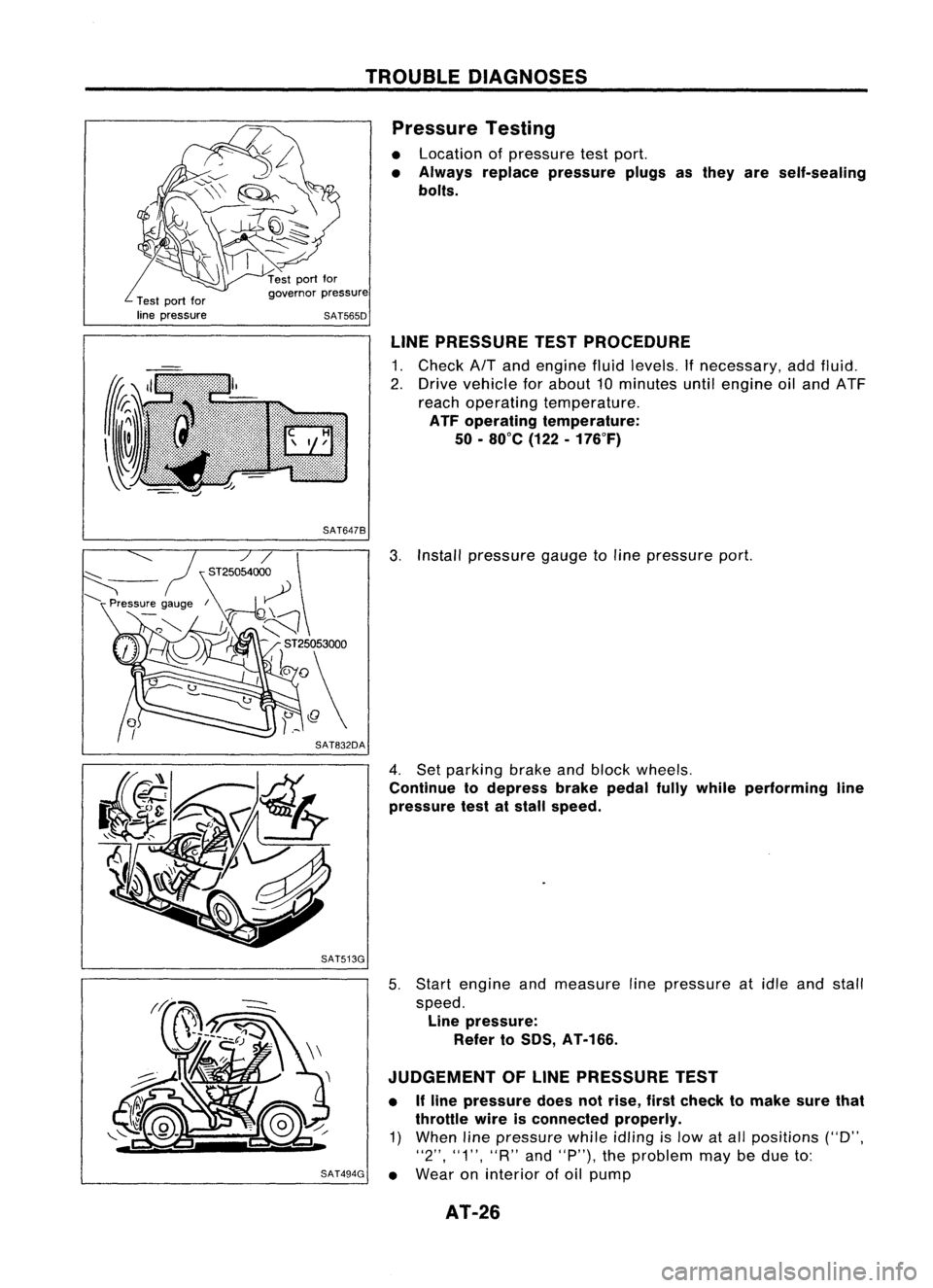
• Location ofpressure testport.
• Always replace pressure plugsasthey areself-sealing
bolts.
Test portfor
line pressure governor
pressure
SAT565D
LINEPRESSURE TESTPROCEDURE
1. Check AfTand engine fluidlevels. Ifnecessary, addfluid.
2. Drive vehicle forabout 10minutes untilengine oiland ATF
reach operating temperature.
ATF operating temperature:
50 -80°C (122-176°F)
SAT647B
3.Install pressure gaugetoline pressure port.
4. Set parking brakeandblock wheels.
Continue todepress brakepedalfullywhile performing line
pressure testatstall speed.
SAT513G
5.Start engine andmeasure linepressure atidle and stall
speed. Line pressure:
Refer toSOS, AT-166.
JUDGEMENT OFLINE PRESSURE TEST
• Ifline pressure doesnotrise, firstcheck tomake surethat
throttle wireisconnected properly.
1) When linepressure whileidling
is
low atall positions ("D",
"2", "1", "R"and"P"), theproblem maybedue to:
SAT494G •
Wear oninterior ofoil pump
AT-26
Page 87 of 1701

REPAIRFORCOMPONENT PARTS
Control ValveUpper Body(Cont'd)
DISASSEMBL Y
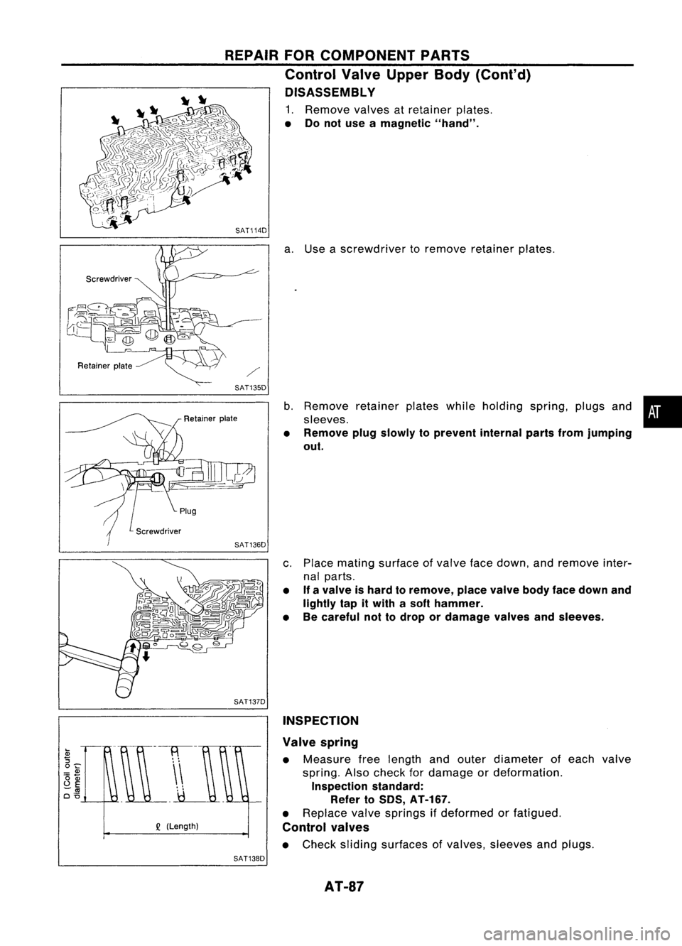
1. Remove valvesatretainer plates.
• Donot use amagnetic "hand".
SAT114D
a.Use ascrewdriver toremove retainer plates.
SAT135D
b.Remove retainerplateswhileholding spring,plugsand•
sleeves.
• Remove plugslowly toprevent internalpartsfromjumping
out.
c. Place mating surface ofvalve facedown, andremove inter-
nal parts.
• If
avalve ishard toremove, placevalvebodyfacedown and
lightly tapitwith asoft hammer.
• Becareful nottodrop ordamage valvesandsleeves.
SAT137D INSPECTION
Q
(Length) Valve
spring
• Measure freelength andouter diameter ofeach valve
spring. Alsocheck fordamage ordeformation.
Inspection standard:
Refer to50S, AT-167.
• Replace valvesprings ifdeformed orfatigued.
Control valves
• Check sliding surfaces ofvalves, sleeves andplugs.
SAT138D
AT-87
Page 91 of 1701

REPAIRFORCOMPONENT PARTS
Control ValveLower Body(Cont'd)
DISASSEMBL Y
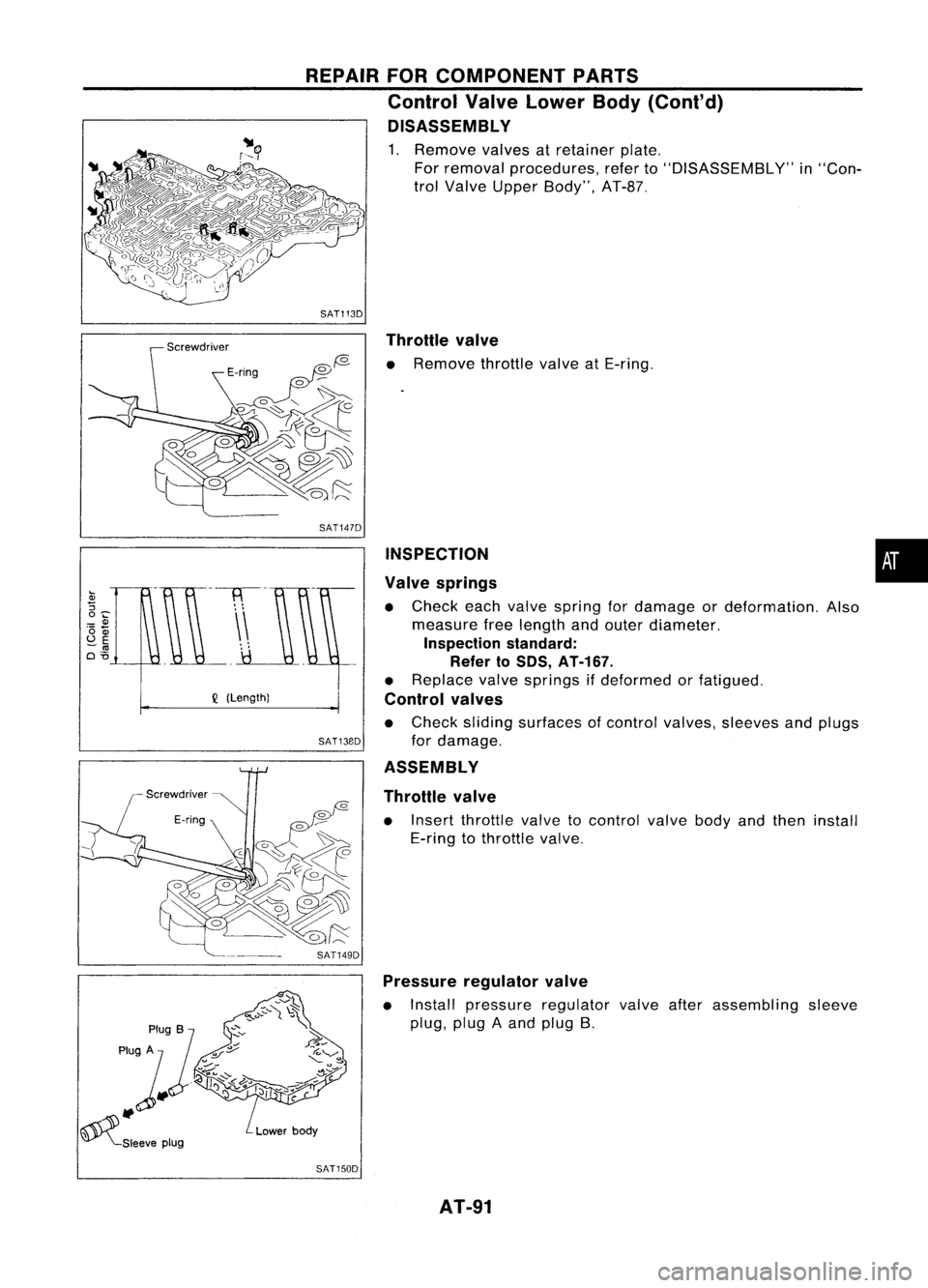
1. Remove valvesatretainer plate.
For removal procedures, referto"DISASSEMBLY" in"Con-
trol Valve Upper Body", AT-B?
SAT1130 Throttle valve
o
f2- •
Remove throttlevalveatE-ring.
•
INSPECTION
Valve springs
• Check eachvalve spring fordamage ordeformation. Also
measure freelength andouter diameter.
Inspection standard:
Refer to50S, AT-167.
• Replace valvesprings ifdeformed orfatigued.
Control valves
• Check sliding surfaces ofcontrol valves, sleeves andplugs
for damage.
ASSEMBLY
Throttle valve
• Insert throttle valvetocontrol valvebodyandthen install
E-ring tothrottle valve.
SAT147D
SAT13BO
Q
(Length)
SAT1490Pressure regulator valve
• Install pressure regulator valveafterassembling sleeve
plug, plugAand plug B.
SAT1500 AT-91
Page 92 of 1701

REPAIRFORCOMPONENT PARTS
Control ValveLower Body(Cont'd)
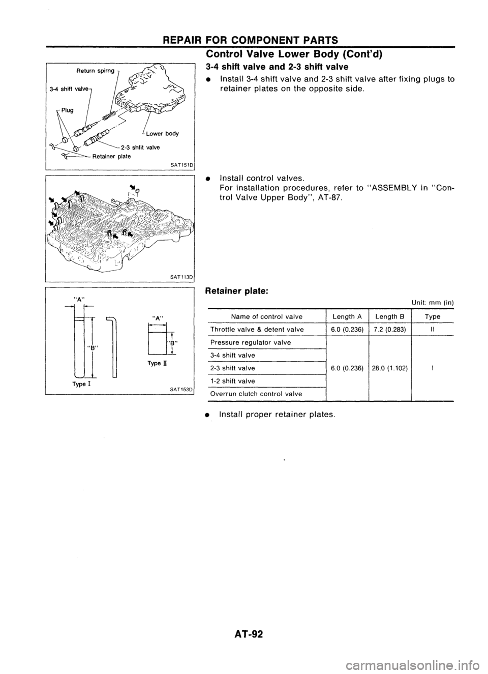
3-4 shift valve and2-3shift valve
• Install 3-4shift valve and2-3shift valve afterfixing plugsto
retainer platesonthe opposite side.
SAT151D
•Install control valves.
For installation procedures, referto"ASSEMBLY in"Con-
trol Valve Upper Body", AT-8?
SAT113D
"A"
"B"
U
Type I
"A"
Eli
Type II
SAT153D Retainer
plate:
Unit:mm(in)
Name ofcontrol
valve
Length
ALength 8 Type
Throttle
valve
&
detent
valve 6.0(0.236) 7.2(0.283)
1/
Pressure regulator
valve
3-4
shift
valve
2-3
shift valve
6.0(0.236) 28.0(1.102)
I
1-2
shift valve
Overrun
clutchcontrol
valve
• Install proper retainer plates.
AT-92
Page 772 of 1701

ON-BOARDDIAGNOSTIC SYSTEMDESCRIPTION
CONSULT (Cont'd)
ACTIVE TESTMODE
TEST ITEM CONDITION JUDGEMENT
CHECKITEM(REMEDY)
• Engine: Returntothe original
•Harness andconnector
FUEL INJECTION trouble
condition If
trouble symptom disappears,
•Fuel injectors
• Change theamount offuel see
CHECK ITEM.
injection usingCONSULT . •
Oxygen sensor*1
• Engine: Afterwarming up,idle
IACV-AACIV the
engine.
Enginespeedchanges according •Harness andconnector
OPENING •
Change theIACV-AAC valve
tothe opening percent. •
IACV-AAC valve
opening percentusingCON-
SULT.
• Engine: Returntothe original
•Harness andconnector
ENG COOLANT trouble
condition
Iftrouble symptom disappears, •
Engine coolant temperature
TEMP •
Change theengine coolant
.
see CHECK ITEM. sensor
temperature indicationusing
•Fuel injectors
CONSULT.
• Engine: Returntothe original
trouble condition
Iftrouble symptom disappears,
IGNITION TIMING•
Timing light:Set •
Adjust initialignition timing
• Retard theignition timingusingsee
CHECK ITEM.
CONSULT .
• Engine: Afterwarming up,idle •
Harness andconnector
the engine. •
Compression
POWER •
A/C switch "OFF"
Enginerunsrough ordies . •
Injectors
BALANCE •
Shift lever "N" •
Power transistor
• Cut offeach injector signalone •
Spark plugs
at atime using CONSULT. •
Ignition coils
• Ignition switch:ON
COOLING FAN*3•
Turn thecooling fan"ON" and
Cooling fanmoves andstops. •
Harness andconnector
"OFF", or"LOW" and"HI" •
Cooling fanmotor
and "OFF" usingCONSULT .
• Ignition switch:ON(Engine
FUEL PUMP stopped)
Fuelpump relaymakes theoper- •Harness andconnector
• Turn thefuel pump relay"ON"
RELAY and"OFF" usingCONSULT ating
sound. •
Fuel pump relay
and listen tooperating sound.
EGRC SOLENOID
VALVE (EVAP canister
•Ignition switch:ON
purge control
•Turn solenoid valve"ON" and Solenoid
valvemakes anoperat- •
Harness andconnector
solenoid valveor
EGR valve
&
"OFF"
withtheCONSULT andingsound. •
Solenoid valve
EVAP canister listen
tooperating sound.
purge control
solenoid valve)
•Ignition switch:ON
VALVE TIMING •
Turn solenoid valve"ON" and Solenoid
valvemakes anoperat- •
Harness andconnector
SOL*2 "OFF"
usingCONSULT anding
sound. •
Solenoid valve
listen tooperating sound.
SELF-LEARNING •
Inthis test, thecoefficient ofself-learning controlmixture ratioreturns tothe original coefficient by
CONT touching
"CLEAR" onthe screen.
*1: Heated oxygen sensor(ForEurope andIsrael, andAustralia A/Tmodels)
Oxygen sensor(Except forEurope andIsrael, andAustralia A/Tmodels)
*2: GA16DE except forEurope andIsrael
*3: GA16DE engine A/Tmodels forEurope without heavydutykithave a2- step control [ON/OFF] system."LOW"and"HI"
are shown onCONSULT screentorepresent "ON"condition.
EC-53
•
Page 777 of 1701

TROUBLEDIAGNOSIS -General Description
Sensors
~ ECMActuators
~~.~ MEF036D
SEF234G Introduction
The engine hasanECM tocontrol majorsystems suchasfuel
control, ignitioncontrol, idleaircontrol system, etc.The ECM
accepts inputsignals fromsensors andinstantly drivesactua-
tors. Itis essential thatboth input andoutput signals areproper
and stable. Atthe same time,itis important thatthere areno
problems suchasvacuum leaks,fouled sparkplugs, orother
problems withtheengine.
It is much moredifficult todiagnose aproblem thatoccurs
intermittently ratherthancontinuously. Mostintermittent prob-
lems arecaused bypoor electric connections orimproper wir-
ing. Inthis case, careful checking ofsuspected circuitsmay
help prevent thereplacement ofgood parts.
A visual checkonlymaynotfind thecause ofthe problems. A
road testwith CONSULT oracircuit testerconnected shouldbe
performed. Followthe"Work Flow"onthe next page.
Before undertaking actualchecks, takejustafew minutes to
talk with acustomer whoapproaches withadriveability com-
plaint. Thecustomer cansupply goodinformation aboutsuch
problems, especially intermittent ones.Findoutwhat symptoms
are present andunder whatconditions theyoccur. A"Diagnos-
tic Worksheet" liketheexample onEC-61 should beused.
Start yourdiagnosis bylooking for"conventional" problems
first. Thiswillhelp troubleshoot driveabilityproblemsonan
electronically controlledenginevehicle.
EC-58
Page 978 of 1701

ON-BOARDDIAGNOSTIC SYSTEMDESCRIPTION
CONSULT (Conl'd)
ACTIVE TESTMODE
TEST ITEM CONDITION JUDGEMENTCHECKITEM(REMEDY)
• Engine: Returntothe original
•Harness andconnector
FUEL INJECTION trouble
condition
Iftrouble symptom disappears,
•Fuel injectors
• Change theamount offuel
seeCHECK ITEM.
•Heated oxygen sensor
injection usingCONSULT .
• Engine: Afterwarming up,idle
IACV-AACIV the
engine.
Enginespeedchanges according •Harness andconnector
OPENING •
Change theIACV-AAC valve
tothe opening percent. •
IACV-AAC valve
opening percentusingCON-
SULT.
• Engine: Returntothe original
•Harness andconnector
ENG COOLANT trouble
condition
Iftrouble symptom disappears, •
Engine coolant temperature
• Change theengine coolant
.
TEMP see
CHECK ITEM. sensor
temperature indicationusing
•Fuel injectors
CONSULT .
• Engine: Returntothe original
trouble condition
Iftrouble symptom disappears,
IGNITION TIMING•Timing light:Set •
Adjust initialignition timing
• Retard theignition timingusingsee
CHECK ITEM.
CONSULT.
• Engine: Afterwarming up,idle •
Harness andconnector
the engine. •
Compression
POWER
•
AIC
switch "OFF"
Enginerunsrough ordies. •
Injectors
BALANCE •
Shift lever "N" •
Power transistor
• Cut offeach injector signalone •
Spark plugs
at atime using CONSULT . •
Ignition coils
• Ignition switch:ON
•Harness andconnector
COOLING FAN•
Turn thecooling fan"ON" andCooling
fanmoves andstops.
•Cooling fanmotor
"OFF" usingCONSULT .
• Ignition switch:ON(Engine
FUEL PUMP stopped)
Fuelpump relaymakes theoper- •
Harness andconnector
RELAY •
Turn thefuel pump relay"ON"
atingsound. •
Fuel pump relay
and "OFF" usingCONSULT
and listen tooperating sound.
EGRC •
Ignition switch:ON
• Turn solenoid valve"ON"and Solenoid
valvemakes anoperat- •
Harness andconnector
SOLENOID "OFF"withtheCONSULT andingsound. •
Solenoid valve
VALVE listentooperating sound.
SELF-LEARNING •
In this test, thecoefficient ofself-learning controlmixture ratioreturns tothe original coefficient by
CONT touching
"CLEAR" onthe screen.
EC-259
•