Page 1091 of 1701
VE-TVPEINJECTION PUMP
G)
Engine slinger
@
Rear backcover
@
Injection pumpsprocket
@
Injection pumpbracket
@
Bracket
@
Bracket
(J)
Water hoses
@
Injection pump
@ Key
Removal
1. Put amatchmark acrossinjection pumpandinjection pump
bracket.
2. Disconnect battery
e
cable, electrical connectors and
accelerator wire.
3. Set No.1 piston atTDe onitscompression stroke.
TOC: Crankshaft pulleynotchwithout painted mark
4. Disconnect waterhoses forcold start device.
5. Remove fuelhoses (supply, returnandspill) andinjection
tubes.
6. Remove airduct andinjection pumptiming beltcover.
7. Remove injection pumptiming belt.
Refer toEM section ("Injection PumpTiming. Belt").
EC-372
Page 1092 of 1701
VE-TVPEINJECTION PUMP ~
Removal (Cont'd)
8. Remove injection pumpsprocket withTool.
• Remove keyfrom injection pumpshaftandstore safely .
9. Remove injection pumpassembly.
Installation
1. With matchmarks aligned,installinjection pump.
2. Install keyoninjection pumpshaft,theninstall injectiol
pump sprocket.
• Use mark "A"onsprocket.
3. Install injection pumptiming belt.
Refer toEM section ("Injection PumpTiming Belt").
SEF155R
4.Adjust injection timing.
Refer to"Adjustment" onthe next page.
5. Install allparts removed.
EC-373
•
Page 1151 of 1701
ENGINECOOLING SYSTEM
IiJ
6.28 -8.34 (0.641 -0.851, 55.6-73.8)
SEC.
210 Water
Pump
~ 6.28 -8.34 (0.641 -0.851, 55.6-73.8)
WaterpumppUlley
l
~Liquid gasket
~ N.m(kg-m, in-Ib)
SLC989AB
•
CAUTION:
• When removing waterpumpassembly, becareful nottoget
coolant ontiming chain.
• Water pumpcannot bedisassembled andshould be
replaced asaunit.
• After installing waterpump, connect hoseandclamp
securely, thencheck forleaks using radiator captester.
REMOVAL
1. Drain coolant fromradiator andcylinder block.
2. Remove drivebeltsforcompressor, powersteering pump
and alternator.
3. Remove waterpumppulley.
4. Remove waterpump.
INSPECTION
1. Check bodyassembly forrust orcorrosion.
2. Check forrough operation duetoexcessive endplay.
SLC162A LC-13
Page 1165 of 1701

ENGINELUBRICATION SYSTEM
SLC926.A Ifdifference isextreme, checkoilpassage andoilpump foroil
leaks.
6. Install oilpressure switchwithsealant.
ST25052000
3.
Install pressure gauge.
4. Start engine andwarm itup tonormal operating tempera-
ture.
5 .. Check oilpressure withengine running underno-load.
•
Approximate dischargepressure
kPa (bar,
kg/cm
2,
psi)
More than59(0.59, 0.6,9)
294 (2.9, 3,43)
Idle
speed
2,000
Engine
rpm
Oil
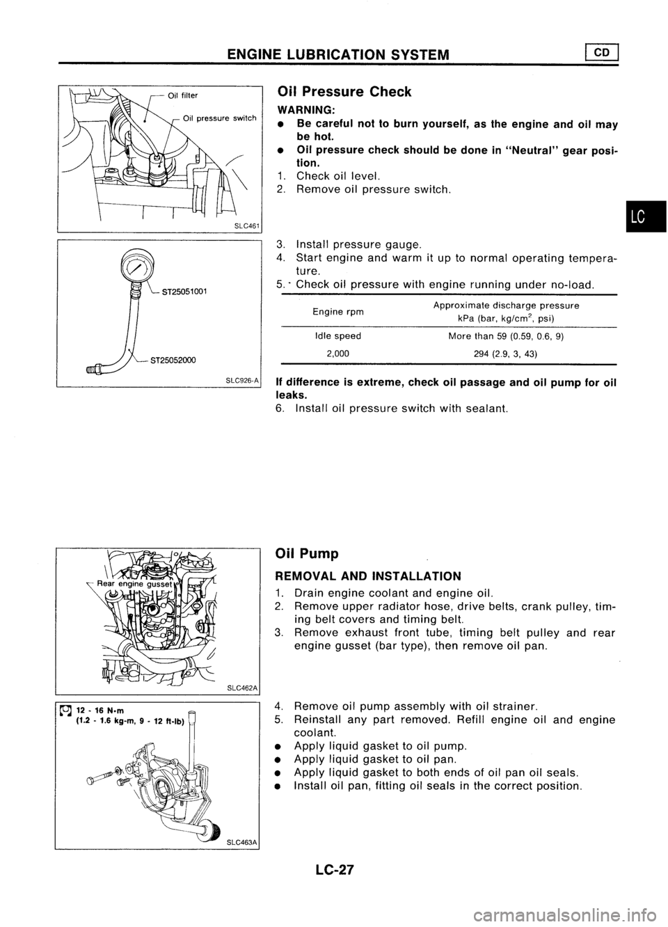
Pressure Check
WARNING: • Becareful nottoburn yourself, asthe engine andoilmay
be hot.
• Oilpressure checkshould bedone in"Neutral" gearposi-
tion.
1. Check oillevel.
2. Remove oilpressure switch.
SLC461
Oil
pressure switch
ST25051 001
~ 12.16 N.m
(1.2 .1.6 kg-m, 9-
12 ft.lb) SLC462A
SLC463A Oil
Pump
REMOVAL ANDINSTAllATION
1. Drain engine coolant andengine oil.
2. Remove upperradiator hose,drivebelts, crank pulley, tim-
ing belt covers andtiming belt.
3. Remove exhaustfronttube, timing beltpulley andrear
engine gusset(bartype), thenremove oilpan.
4. Remove oilpump assembly withoilstrainer.
5. Reinstall anypart removed. Refillengine oiland engine
coolant.
• Apply liquidgasket tooil pump.
• Apply liquidgasket tooil pan.
• Apply liquidgasket toboth ends ofoil pan oilseals.
• Install oilpan, fitting oilseals inthe correct position.
LC-27
Page 1171 of 1701
ENGINECOOLING SYSTEM
Water Pump
REMOVAL ANDINSTALLATION
1. Drain engine coolant fromradiator andcylinder block.
2. Remove upperradiator hose,timing beltcovers, front
engine mounting bracketandtiming belt.
3. Remove timingbelttensioner andidler andtiming belt
lower backcover.
~
Drain plug(Radiator)
4.Remove waterpump.
• For installation, applyliquidgasket towater pumpasshown
in the figure.
2.5:!:0.5
Bolt hRille (0.098:!:0.020r12.5:!: 0.5
die. (0.098:!:0.020)
dIe.
Unit: mm(in) SLC565A
*:
Apply liquidsealant tothe thread.
~/ ~~;>
~/ ~l!.
to.J
M7: 16-20 N.m (1.6-2.0 kg-m, 12-14 ft-Ib)
M8: 16-21 N.m (1.6-2.1 kg-m, 12-15 ft-Ib)
SLC563A
LC-33
•
Page 1181 of 1701
CONTENTS(Conl'd.)
TIMING BELT
120
Camshaft TimingBelt 120
Injection PumpTiming Belt 124
OIL SEAL REPLACEMENT
126
CYLINDER HEAD 128
Removal 129
Disassembly 129
Inspection 130
Assembly 136
Installation 137
ENGINE REMOVAL
140
CYLINDER
BLOCK 143
Preparation 144
Disassembly 144
Inspection 145
Assembly 152
GA
SERVICE DATAANDSPECIFICATIONS
(505)
155
General Specifications ,155
Inspection andAdjustment. 156
SR
SERVICE DATAANDSPECIFICATIONS
(505)
163
General Specifications 163
Inspection andAdjustment. 163
CD
SERVICE DATAANDSPECIFICATIONS
(50S)
171
Inspection andAdjustment.. 171
Page 1199 of 1701

TIMINGCHAIN
Without
VTC
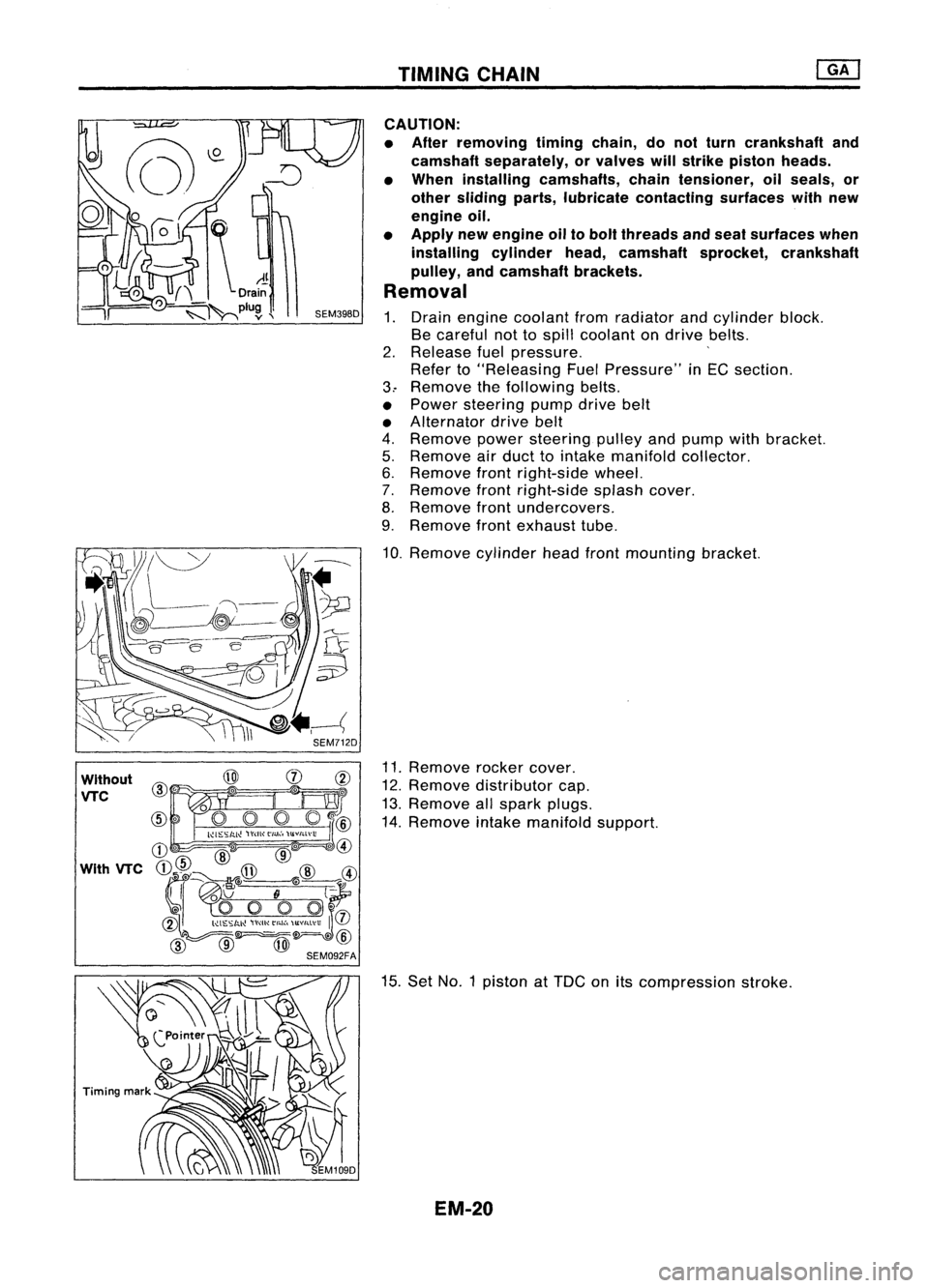
CAUTION:
• After removing timingchain,donot turn crankshaft and
camshaft separately, orvalves willstrike piston heads.
• When installing camshafts, chaintensioner, oilseals, or
other sliding parts,lubricate contacting surfaceswithnew
engine oil.
• Apply newengine oiltobolt threads andseat surfaces when
installing cylinderhead,camshaft sprocket,crankshaft
pulley, andcamshaft brackets.
Removal
1. Drain engine coolant fromradiator andcylinder block.
Be careful nottospill coolant ondrive belts.
2. Release fuelpressure. '
Refer to"Releasing FuelPressure" inEG section.
3.. Remove thefollowing belts.
• Power steering pumpdrivebelt
• Alternator drivebelt
4. Remove powersteering pulleyandpump withbracket.
5. Remove airduct tointake manifold collector.
6. Remove frontright-side wheel.
7. Remove frontright-side splashcover.
8. Remove frontundercovers.
9. Remove frontexhaust tube.
10. Remove cylinderheadfrontmounting bracket.
11. Remove rockercover.
12. Remove distributor cap.
13. Remove allspark plugs.
14. Remove intakemanifold support.
15. Set NO.1 piston at
TOG
onitscompression stroke.
EM-20
Page 1208 of 1701

WithoutVTC
Engine front
Unit: mm(in)
~(0.39)
~1-J--10 (0.39)
* -\
3 (0.12)
Z~
Liquid
gasket
SEM59BEA TIMING
CHAIN
Installation (Cont'd)
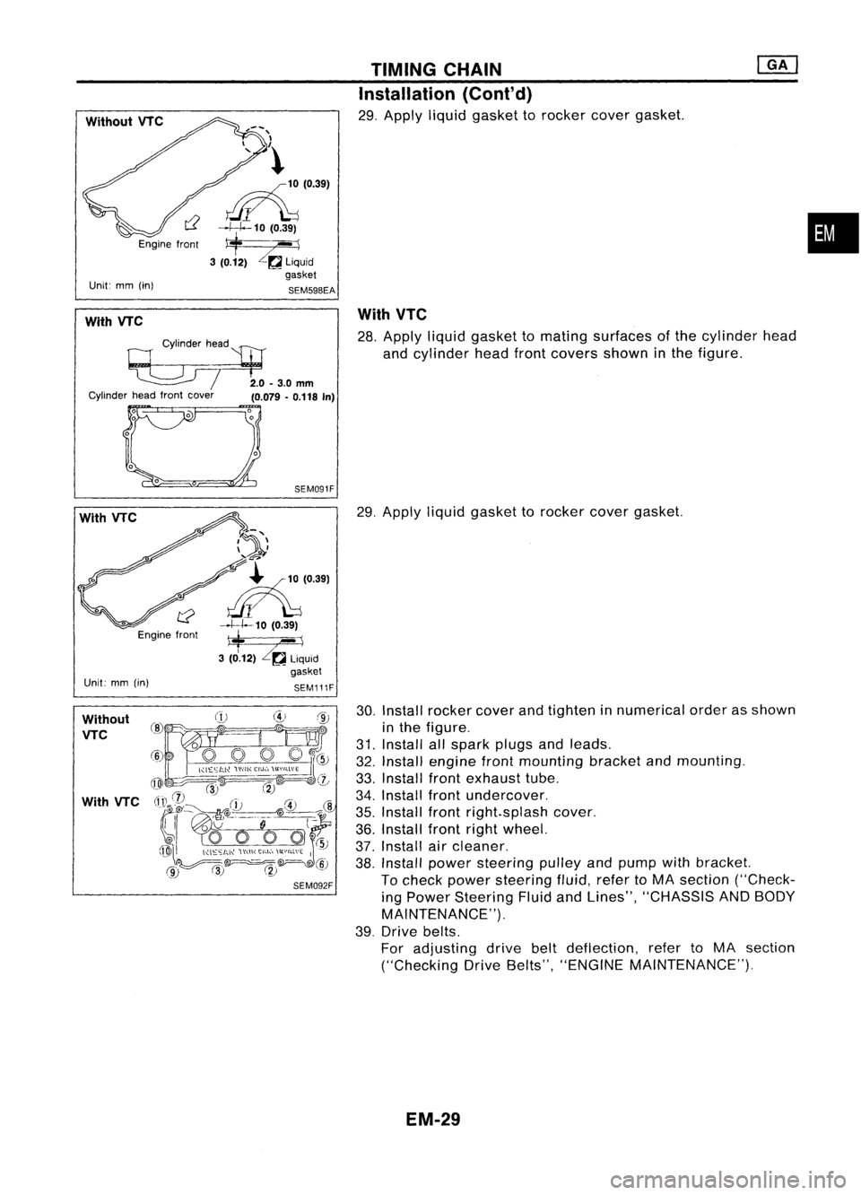
29. Apply liquidgasket torocker covergasket.
•
With VTC
Cylinderhead
'l:tJ
~ /2.0-3.0mm
Cylinder headfront cover
(0.079-0.118 In)
With
VTC
28. Apply liquidgasket tomating surfaces ofthe cylinder head
and cylinder headfrontcovers showninthe figure.
With VTC
Engine front
Unit: mm(in)
SEM091F
7~'\
\ ..... -4'
~-'?
~'0391
~10 (0.39)
*
--1
3 (0.12)
Zr.a
liquid
gasket
SEM111F
29.
Apply liquidgasket torocker covergasket.
Without VTC
With VTC
30.
Install rocker coverandtighten innumerical orderasshown
in the figure.
31. Install allspark plugsandleads.
32. Install engine frontmounting bracketandmounting.
33. Install frontexhaust tube.
34. Install frontundercover.
35. Install frontright.splash cover.
36. Install frontrightwheel.
37. Install aircleaner.
38. Install power steering pulleyandpump withbracket.
To check power steering fluid,refertoMA section ("Check-
ing Power Steering FluidandLines", "CHASSIS ANDBODY
MAINTENANCE").
39. Drive belts.
For adjusting drivebeltdeflection, refertoMA section
("Checking DriveBelts", "ENGINE MAINTENANCE").
EM-29