1995 NISSAN ALMERA N15 timing belt
[x] Cancel search: timing beltPage 1303 of 1701
![NISSAN ALMERA N15 1995 Service Manual TIMINGBELT
@[]
Camshaft TimingBelt(Cont'd)
5. Install timing beltwith crankshaft sprocket.
a. Align white linesontiming beltwith punchmarks oncam-
shaft sprocket andcrankshaft sprocket.
b. Poi](/manual-img/5/57349/w960_57349-1302.png "NISSAN ALMERA N15 1995 Service Manual TIMINGBELT
@[]
Camshaft TimingBelt(Cont'd)
5. Install timing beltwith crankshaft sprocket.
a. Align white linesontiming beltwith punchmarks oncam-
shaft sprocket andcrankshaft sprocket.
b. Poi")
TIMINGBELT
@[]
Camshaft TimingBelt(Cont'd)
5. Install timing beltwith crankshaft sprocket.
a. Align white linesontiming beltwith punchmarks oncam-
shaft sprocket andcrankshaft sprocket.
b. Point arrow ontiming belttoward beltcover.
6. Install camshaft sprocketplateandsecure screws withlock-
tite.
7. Adjust timing belttension.
1) Loosen tensioner lockbolttoapply tension totiming belt.
2) Rotate crankshaft clockwisetwoturns toapply thespecified
tension totiming belt.
3) Tighten tensioner lockboltwhile holding tensioner pUlley
with hexagon wrench. .
Belt tension:
147.1 :1:24.5 N(15:1:2.5 kg,33.1 :1:5.5 Ib)
SEM520D Injection PumpTiming Belt
~ .N'm (kg-m, in-Ib)
~ :N.m (kg-m, ft-Ib)
SEC.
130-135
~
-"~
.~\(~[-~~' c~1
Timingbelt
?\~-d
(~K.
c
'0
t£
Tensioner spring
J
J
N
0~lJ'00 ~/ Tensioner
t0
J
l\J~.~l:~
'Gl
~')U
r
r~/~
16-21 (1.6 -2.1,12 -15)
It
I
L~0--~ '
~htiJ
JD/~h~J/ "
'SP/
_-z,}) ~A
[/ ......., ....... InJeclion~
.... ~. -;;, pump@J_
• '~~ sprocket~
"fc;,~~-
@ ~
59-
69-.1
Rear camshaft sprocket .~(6.0•7.0,
1m
43-51)
[O;l
87•107
(8.9 -10.9, 64•79)
SEM225F
REMOVAL
1. Set NO.1 cylinder atTDC onitscompression stroke.(TDC
is indicated bycrankshaft pulleynotchwithout painted
mark.)
2. Remove airduct withresonator andtiming beltcover.
EM-124
Page 1304 of 1701
![NISSAN ALMERA N15 1995 Service Manual
InjectionpumppUlley
TIMING
BELT
[fQ]
Injection PumpTiming Belt(Cont'd)
3. Remove timingbelt.
1) Loosen tensioner locknutand turn tensioner clockwise to
free beltfrom tension. Thentemporarily](/manual-img/5/57349/w960_57349-1303.png "NISSAN ALMERA N15 1995 Service Manual
InjectionpumppUlley
TIMING
BELT
[fQ]
Injection PumpTiming Belt(Cont'd)
3. Remove timingbelt.
1) Loosen tensioner locknutand turn tensioner clockwise to
free beltfrom tension. Thentemporarily")
InjectionpumppUlley
TIMING
BELT
[fQ]
Injection PumpTiming Belt(Cont'd)
3. Remove timingbelt.
1) Loosen tensioner locknutand turn tensioner clockwise to
free beltfrom tension. Thentemporarily tightentensioner
nut.
2) Remove timingbelt.
INSTAllATION
1. Confirm thatNO.1 piston isset atTDC onitscompression
stroke. (TDCisindicated bycrankshaft pulleynotchwithout
painted mark.)
• Ifinjection pumppulley wasremoved, confirmthatitis
re-installed asillustrated.
Identification ofalignment:
Use mark "A"
2. Set timing belt.
a. Align white linesontiming beltwith punchmarks oncam-
shaft sprocket andinjection pumpsprocket.
b. Point arrow ontiming belttoward beltcover.
3. Adjust belttension.
1) Loosen tensioner locknuttoapply tension totiming belt.
2) Rotate crankshaft clockwisetwoturns.
Do not turn crankshaft bycamshaft sprockets.
3) Tighten tensioner locknutwhile holding tensioner witha
screwdriver.
Belt tension:
147:l:49 N(15:l:5 kg,33:l:11 Ib)
INSPECTION
Refer toINSPECTION in"Camshaft TimingBelt"(EM-122).
INJECTION TIMINGADJUSTMENT
Refer toEC section.
EM-125
•
Page 1305 of 1701
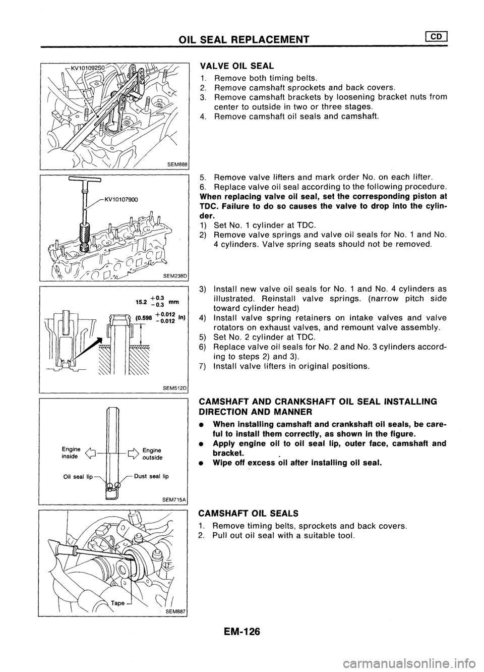
OILSEAL REPLACEMENT
Install newvalve oilseals forNo.1 andNO.4 cylinders as
illustrated. Reinstallvalvesprings. (narrowpitchside
toward cylinder head)
Install valvespring retainers onintake valves andvalve
rotators onexhaust valves,andremount valveassembly.
Set NO.2 cylinder at
TOG.
Replace valveoilseals forNo.2 andNo.3 cylinders accord-
ing tosteps 2)and 3).
Install valvelifters inoriginal positions.
5.
Remove valveliftersandmark order No.oneach lifter.
6. Replace valveoilseal according tothe following procedure.
When replacing valveallseal, setthe corresponding pistonat
TOe. Failure todo socauses thevalve todrop intothecylin-
der.
1) Set NO.1 cylinder at
TOG.
2) Remove valvesprings andvalve oilseals forNO.1 andNo.
4 cylinders. Valvespring seatsshould notberemoved.
VALVE
OilSEAL
1. Remove bothtiming belts.
2. Remove camshaft sprockets andback covers.
3. Remove camshaft bracketsbyloosening bracketnutsfrom
center tooutside intwo orthree stages.
4. Remove camshaft oilseals andcamshaft.
3)
+0.3
15.2 -0.3
mm
(0598
+0.012
In)
4)
. -0.012
5)
6)
~ 7)
SEM512D
Engine
/'t
inside
Y
r-l'\.
Engine
LV outside CAMSHAFT
ANDCRANKSHAFT OilSEAL INSTALLING
DIRECTION ANDMANNER
• When installing camshaftandcrankshaft oilseals, becare-
ful toinstall themcorrectly, asshown inthe figure.
• Apply engine oiltooil seal lip,outer face,camshaft and
bracket. .
• Wipe offexcess allafter installing oilseal.
Oil seal lip Dust
seallip
SEM715A CAMSHAFT OilSEALS
1. Remove timingbelts,sprockets andback covers.
2. Pull outoilseal withasuitable tool.
EM-126
Page 1306 of 1701

OILSEAL REPLACEMENT
3. Install newoilseals withasuitable tool.
Confirm turningdirection ofboth oilseals andcamshaft .
•
Rear
Front
SEM240D
CRANKSHAFT FRONTOILSEAL
1. Remove valvetiming beltandcrankshaft sprocket.
2. Remove oilseal withasuitable tool.
3. Apply engine oiltonew oilseal andinstall oilseal using a
suitable tool.
CRANKSHAFT REAROILSEAL
1. Remove transaxle assembly. (Referto"REMOVAL AND
INSTALLATION" in
MT
section.)
2. Remove flywheel.
3. Remove rearoilseal withasuitable tool.
4. Apply engine oiltonew oilseal andinstall oilseal using a
suitable tool.
EM-127
Page 1308 of 1701
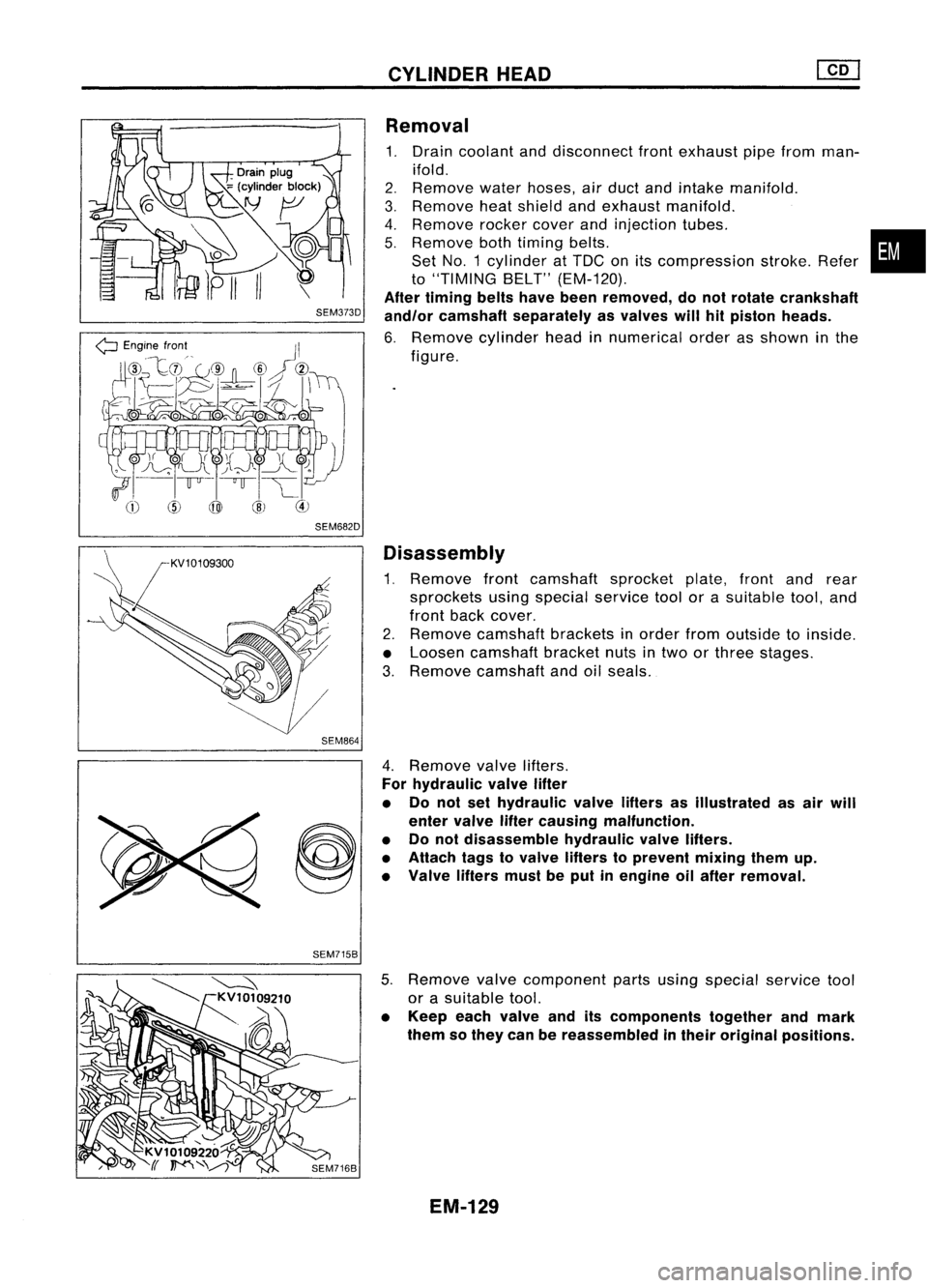
SEM373D
SEM682D SEM864
CYLINDER
HEAD
Removal
1. Drain coolant anddisconnect frontexhaust pipefrom man-
ifold.
2. Remove
waterhoses, airduct andintake manifold.
3. Remove
heatshield andexhaust manifold.
4. Remove
rocker
cover
andinjection tubes.
5. Remove
bothtiming belts.
Set NO.1 cylinder atTDC onitscompression stroke.Refer
to
"TIMING BELT"(EM-120).
After timing beltshavebeen removed, donot rotate crankshaft
and/or camshaft separately asvalves willhitpiston heads.
6. Remove
cylinderheadinnumerical orderasshown inthe
figure.
Disassembly
1. Remove frontcamshaft sprocketplate,frontandrear
sprockets usingspecial
service
toolorasuitable tool,and
front back
cover.
2. Remove
camshaft bracketsinorder fromoutside toinside.
• Loosen camshaft bracketnutsintwo orthree stages.
3. Remove
camshaft andoilseals.
•
SEM715B 4.
Remove valve
lifters.
For hydraulic valvelifter
• Do not sethydraulic valvelifters asillustrated asair will
enter valve liftercausing malfunction.
• Donot disassemble hydraulicvalvelifters.
• Attach tagstovalve lifters toprevent mixingthemup.
• Valve liftersmustbeput inengine oilafter removal.
5. Remove
valve
component partsusing special
service
tool
or asuitable tool.
• Keep eachvalve anditscomponents togetherandmark
them sothey canbereassembled intheir original positions.
EM-129
Page 1323 of 1701
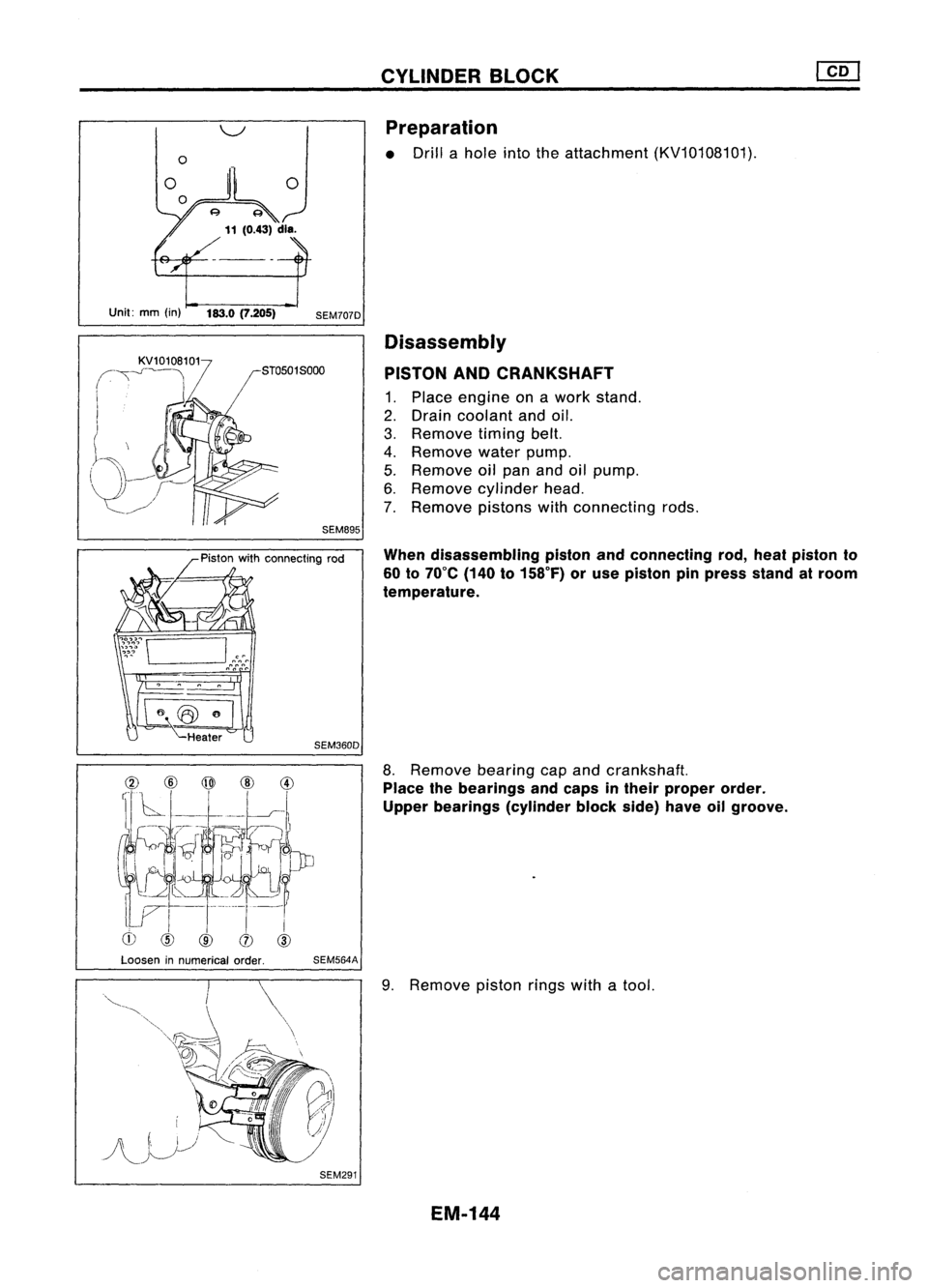
Unit:mm(in) 183.0(7.205)
SEM707DCYLINDER
BLOCK
Preparation
• Drill ahole intotheattachment (KV10108101).
Disassembly
PISTON ANDCRANKSHAFT
1. Place engine onawork stand.
2. Drain coolant andoil.
3. Remove timingbelt.
4. Remove waterpump.
5. Remove oilpan andoilpump.
6. Remove cylinder head.
7. Remove pistonswithconnecting rods.
When disassembling pistonandconnecting rod,heat piston to
60 to70°C (140to158°F) oruse piston pinpress standatroom
temperature.
Heater
SEM360D
8.Remove bearingcapand crankshaft.
Place thebearings andcaps intheir proper order.
Upper bearings (cylinderblockside)haveoilgroove.
Loosen innumerical order.
SEM564A
SEM291
9.
Remove pistonringswithatool.
EM-144
Page 1487 of 1701
SECTION
CONTENTS
MAINTENANCE
MA
•
PRECAUTIONS ANDPREPARATION
3
Supplemental RestraintSystem(SRS)"AIR
BAG" (DualAirBag System) 3
Supplemental RestraintSystem(SRS)"AIR
BAG" (Single AirBag System) 3
Special Service Tools 4
Commercial ServiceTool 4
PRE-DELIVERY INSPECTIONITEMS
5
GENERAL MAINTENANCE 6
PERIODIC MAINTENANCE (Exceptfor
Europe) 7
Engine andEmission ControlService 7
Chassis andBody Service 8
Maintenance UnderSevere DrivingConditions 9
PERIODIC MAINTENANCE (ForEurope) 10
Engine Oil
&
Minor Service 10
Engine andEmission ControlService 11
Chassis andBody Services 12
Maintenance UnderSevere Driving Conditions 13
RECOMMENDED LUBRICANTSANDFLUIDS 14
Lubricants andFluids 14
SAE Viscosity Number 15
Anti-freeze CoolantMixtureRatio 16
~ --ll
GA
I I
ENGINE MAINTENANCE 17
Checking DriveBelts 17
Changing EngineCoolant... 19
Checking CoolingSystem 21
Checking FuelLines 22
Changing FuelFilter 22
Cleaning andChanging AirCleaner Filter 23
Changing EngineOil 24
Changing OilFilter 24
Checking andChanging SparkPlugs 25
Checking IgnitionWires 26Changing
PositiveCrankcase Ventilation
(PCV) Filter 26
Checking EVAPVapor Lines 26
Checking OxygenSensor(02S)orHeated
Oxygen Sensor(H02S) 27
~ --ll
SR
I I
ENGINE MAINTENANCE 28
Checking DriveBelts 28
Changing EngineCoolant... 29
Checking CoolingSystem 31
Checking FuelLines 32
Changing FuelFilter 32
Changing AirCleaner Filter 33
Changing EngineOil 33
Changing OilFilter 34
Changing SparkPlugs(Platinum-tipped type)34
Checking IgnitionWires 35
Checking EVAPVapor
&
Purge Lines 36
Checking HeatedOxygen Sensor(H02S) 37
~_~ ..-JI
CD
I I
ENGINE MAINTENANCE
38
Manifold NutCheck 38
Checking DriveBelt 38
Changing EngineCoolant. 38
Checking CoolingSystem .40
Checking FuelLine .40
Changing AirCleaner Filter 41
Water Draining, FuelFilter Check and
Replacement 41
Changing EngineOil .41
Changing EngineOilFilter 42
Checking InjectionNozzle 43
Checking IdleSpeed .44
Replacing TimingBelt 44
Page 1491 of 1701
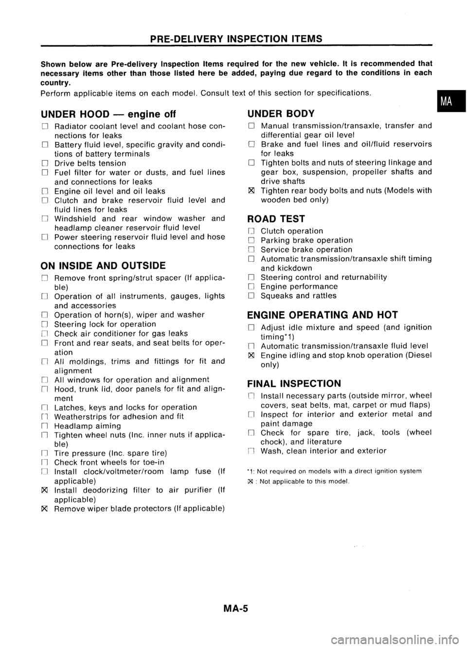
PRE-DELIVERYINSPECTIONITEMS
Shown belowarePre-delivery InspectionItemsrequired forthe new vehicle. Itis recommended that
necessary itemsotherthanthose listedherebeadded, payingdueregard tothe conditions ineach
country.
Perform applicable itemsoneach model. Consult textofthis section forspecifications .
UNDER HOOD-engine off
o
Radiator coolantlevelandcoolant hosecon-
nections forleaks
o
Battery fluidlevel, specific gravityandcondi-
tions ofbattery terminals
o
Drive beltstension
D
Fuel filter forwater ordusts, andfuel lines
and connections forleaks
[] Engine oillevel andoilleaks
D
Clutch andbrake reservoir fluidlevel and
fluid lines forleaks
o
Windshield andrear window washerand
headlamp cleanerreservoir fluidlevel
D
Power steering reservoir fluidlevel andhose
connections forleaks
ON INSIDE ANDOUTSIDE
D
Remove frontspring/strut spacer(Ifapplica-
ble)
D
Operation ofall instruments, gauges,lights
and accessories
o
Operation ofhorn(s), wiperandwasher
[] Steering lockforoperation
[] Check airconditioner forgas leaks
o
Front andrear seats, andseat belts foroper-
ation
n
All moldings, trimsandfittings forfitand
alignment
[J
Allwindows foroperation andalignment
n
Hood, trunklid,door panels forfitand align-
ment
[1
Latches, keysandlocks foroperation
rl
Weatherstrips foradhesion andfit
[l
Headlamp aiming
I~ Tighten wheelnuts(Inc. inner nutsifapplica-
ble)
IJ Tire pressure (Inc.spare tire)
Il
Check frontwheels fortoe-in
IJ Install clock/voltmeter/room lampfuse(If
applicable)
~ Install deodorizing filtertoair purifier (If
applicable)
~ Remove wiperbladeprotectors (Ifapplicable)
UNDER
BODY
o
Manual transmission/transaxle, transferand
differential gearoillevel
D
Brake andfuel lines andoil/fluid reservoirs
for leaks
D
Tighten boltsandnuts ofsteering linkageand
gear box,suspension, propellershaftsand
drive shafts
~ Tighten rearbody boltsandnuts (Models with
wooden bedonly)
ROAD TEST
D
Clutch operation
D
Parking brakeoperation
[J
Service brakeoperation
D
Automatic transmission/transaxle shifttiming
and kickdown
[] Steering controlandreturnability
o
Engine performance
D
Squeaks andrattles
ENGINE OPERATING ANDHOT
D
Adjust idlemixture andspeed (andignition
timing*1)
n
Automatic transmission/transaxle fluidlevel
~ Engine idlingandstop knob operation (Diesel
only)
FINAL INSPECTION
n
Install necessary parts(outside mirror,wheel
covers, seatbelts, mat,carpet ormud flaps)
[1
Inspect forinterior andexterior metaland
paint damage
[] Check forspare tire,jack, tools (wheel
chock), andliterature
n
Wash, cleaninterior andexterior
"1: Not required onmodels withadirect ignition system
~ :Not appiicable tothis model.
•
MA-5