1995 NISSAN ALMERA N15 reset
[x] Cancel search: resetPage 688 of 1701
ON-VEHICLESERVICE
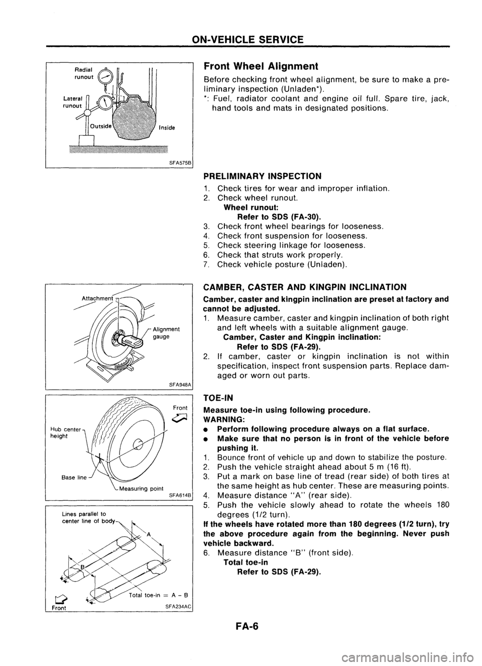
Front Wheel Alignment
Before checking frontwheel alignment, besure tomake apre-
liminary inspection (Unladen*).
*: Fuel, radiator coolantandengine oilfull. Spare tire,jack,
hand tools andmats indesignated positions.
SFA575B PRELIMINARY INSPECTION
1. Check tiresforwear andimproper inflation.
2. Check wheelrunout.
Wheel runout:
Refer toSOS (FA-30).
3. Check frontwheel bearings forlooseness.
4. Check frontsuspension forlooseness.
5. Check steering linkageforlooseness.
6. Check thatstruts workproperly.
7. Check vehicle posture (Unladen).
TOE-IN Measure toe-inusingfollowing procedure.
WARNING:
• Perform following procedure alwaysonaflat surface.
• Make surethatnoperson isin front ofthe vehicle before
pushing it.
1. Bounce frontofvehicle upand down tostabilize theposture.
2. Push thevehicle straight aheadabout5m (16 ft).
3. Put amark onbase lineoftread (rearside) ofboth tires at
the same height ashub center. Thesearemeasuring points.
4. Measure distance"A"(rear side).
5. Push thevehicle slowlyaheadtorotate thewheels 180
degrees (1/2turn).
If the wheels haverotated morethan180degrees
(112
turn), try
the above procedure againfromthebeginning. Neverpush
vehicle backward.
6. Measure distance"B"(front side).
Total toe-in
Refer toSOS (FA-29).
CAMBER,
CASTERANDKINGPIN INCLINATION
Camber, casterandkingpin inclination arepreset atfactory and
cannot beadjusted.
1. Measure camber,casterandkingpin inclination ofboth right
and leftwheels withasuitable alignment gauge.
Camber, CasterandKingpin inclination:
Refer toSOS (FA-29).
2. Ifcamber, casterorkingpin inclination isnot within
specification, inspectfrontsuspension parts.Replace dam-
aged orworn outparts.
Front
SFA948A
SFA614B
SFA234AC
Lines
parallel to
center lineofbody
Q
Front
Hub
center
height
FA-6
Page 743 of 1701
ENGINEANDEMISSION BASICCONTROL SYSTEMDESCRIPTION
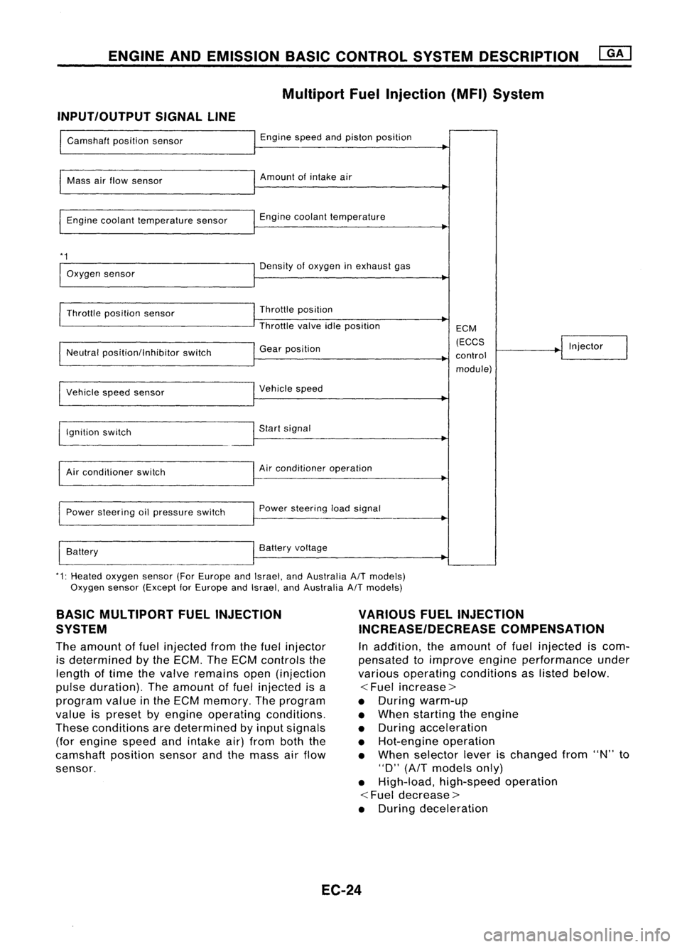
Multipart FuelInjection (MFI)System
INPUT/OUTPUT SIGNALLINE
Camshaft positionsensor
Mass airflow sensor
Engine coolant temperature sensor
*1
Oxygen sensor
Throttle position sensor
Neutral position/Inhibitor switch
Vehicle speedsensor
~gnition switch
Air conditioner switch
Power steering oilpressure switch
Battery Engine
speedandpiston position
Amount ofintake air
Engine coolant temperature
Density ofoxygen inexhaust gas
Throttle position
Throttle valveidleposition
Gear position
Vehicle speed
Start signal
Air conditioner operation
Power steering loadsignal
Battery voltage ECM
(ECCS
control module) Injector
*1: Heated oxygen sensor(ForEurope andIsrael, andAustralia A/Tmodels)
Oxygen sensor(Except forEurope andIsrael, andAustralia A/Tmodels)
BASIC MULTIPORT FUELINJECTION
SYSTEM
The amount offuel injected fromthefuel injector
is determined bythe ECM. TheECM controls the
length oftime thevalve remains open(injection
pulse duration). Theamount offuel injected isa
program valueinthe ECM memory. Theprogram
value ispreset byengine operating conditions.
These conditions aredetermined byinput signals
(for engine speedandintake air)from boththe
camshaft positionsensorandthemass airflow
sensor.
VARIOUS
FUELINJECTION
INCREASE/DECREASE COMPENSATION
In addition, theamount offuel injected iscom-
pensated toimprove engineperformance under
various operating conditions aslisted below.
<
Fuel increase>
• During warm-up
• When starting theengine
• During acceleration
• Hot-engine operation
• When selector leverischanged from"N"to
"D"
(AfT
models only)
• High-load, high-speed operation
<
Fuel decrease>
• During deceleration
EC-24
Page 776 of 1701
![NISSAN ALMERA N15 1995 Service Manual ON-BOARDDIAGNOSTIC SYSTEMDESCRIPTION
[]K]
CONSULT (Cont'd)
REAL TIMEDIAGNOSIS INDATA MONITOR MODE
CONSULT hastwo kinds oftriggers andthey canbeselected bytouching "SETTING" in"DATA
NISSAN ALMERA N15 1995 Service Manual ON-BOARDDIAGNOSTIC SYSTEMDESCRIPTION
[]K]
CONSULT (Cont'd)
REAL TIMEDIAGNOSIS INDATA MONITOR MODE
CONSULT hastwo kinds oftriggers andthey canbeselected bytouching "SETTING" in"DATA](/manual-img/5/57349/w960_57349-775.png)
ON-BOARDDIAGNOSTIC SYSTEMDESCRIPTION
[]K]
CONSULT (Cont'd)
REAL TIMEDIAGNOSIS INDATA MONITOR MODE
CONSULT hastwo kinds oftriggers andthey canbeselected bytouching "SETTING" in"DATA
MONITOR" mode.
1. "AUTO TRIG"(Automatic trigger):
• The malfunction willbeidentified onthe CONSULT screeninreal time.
In other words, DTCandmalfunction itemwillbedisplayed atthe moment themalfunction is
detected byECM.
DATA MONITOR canbeperformed continuously untilamalfunction isdetected. However, DATA
MONITOR cannotcontinue anylonger afterthemalfunction detection.
2. "MANU TRIG"(Manual trigger):
• DTC andmalfunction itemwillnotbedisplayed automatically onCONSULT screeneventhough
a malfunction isdetected byECM. •
DATA MONITOR canbeperformed continuously eventhough amalfunction isdetected.
Use these triggers asfollows:
1. "AUTO TRIG"
• While trying todetect theDTC byperforming the"DTC CONFIRMATION PROCEDURE",besure
to select to"DATA MONITOR (AUTOTRIG)" mode.Youcanconfirm themalfunction atthe
moment itis detected.
• While narrowing downthepossible causes,CONSULT shouldbeset in"DATA MONITOR (AUTO
TRIG)" mode,especially incase theincident isintermittent.
Inspect thecircuit bygently shaking (ortwisting) suspicious connectors, components andharness
in the "DTC CONFIRMATION PROCEDURE".Themoment amalfunction isfound theDTC willbe
displayed. (RefertoGI section, "Incident Simulation Tests"in"HOW TOPERFORM EFFICIENT
DIAGNOSIS FORANELECTRICAL INCIDENT".)
2. "MANU TRIG"
• Ifthe malfunction isdisplayed assoon as"DATA MONITOR" isselected, resetCONSULT to
"MANU TRIG".Byselecting "MANUTRIG"youcanmonitor andstore thedata. Thedata canbe
utilized forfurther diagnosis, suchasacomparison withthevalue forthe normal operating con-
dition.
HISPEED
AUTO
TRIG
I
~
SELECT MONITOR ITEM
ECM INPUT SIGNALS
MAIN SIGNALS
SELECTION FROMMENU
I
~
SET RECORDING COND
I
MANU TRIG
I
LONG TIME HI
SPEED MANU
TRIG
SETTING
II
START
___ 1__ 1
"SETTIN-G" "AUTOTRIG"
A
malfunction canbe
displayed on"DATA
MONITOR" screen
automatically ifdetected.
EC-57 "MANU
TRIG"
A malfunction cannotbe
displayed on"DATA
MONITOR" screen
automatically evenif
detected.
SEF674Q
Page 783 of 1701
TROUBLEDIAGNOSIS -General Description
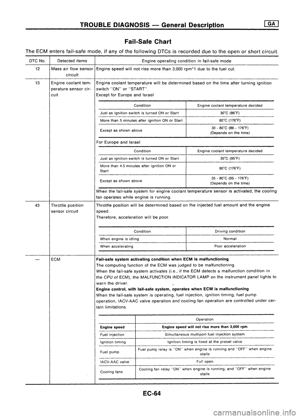
Fail-Safe Chart
The ECM enters fail-safe mode,ifany ofthe following DTCsisrecorded duetothe open orshort circuit.
DTC No. Detected
items
Engineoperating conditioninfail-safe mode
12 Massairflow sensor
Enginespeedwillnotrise more than3,000 rpm*1 duetothe fuel cut.
circuit
13 Engine
coolant tem-
Engine coolant temperature willbedetermined basedonthe time after turning ignition
perature sensorcir-switch "ON"or"START".
cuit ExceptforEurope andIsrael
Condition Enginecoolant temperature decided
Just asignition switchisturned ONorStart 30'C(B6'F)
More than5minutes afterignition ONorStart BO'G
(176'F)
Except asshown above 30
-BO'C (B6-176'F)
(Depends onthe time)
For Europe andIsrael
Condition Enginecoolant temperature decided
Just asignition switchisturned ONorStart 35'C
(95'F)
More than4.5minutes afterignition ONor
BO'G(176'F)
Start
Except asshown above 35
-BO'C (95-176'F)
(Depends onthe time)
When thefail-safe systemforengine coolant temperature sensorisactivated, thecooling
fan operates whileengine isrunning.
43 Throttle position Throttle
position willbedetermined basedonthe injected fuelamount andtheengine
sensor circuit speed.
Therefore, acceleration willbepoor.
Condition Driving
condition
When engine isidling Normal
When accelerating Poor
acceleration
-
ECM
Fail-safe
systemactivating conditionwhenECMismalfunctioning
The computing functionofthe ECM wasjudged tobe malfunctioning.
When thefail-safe systemactivates (i.e.,ifthe ECM detects amalfunction conditionin
the CPU ofECM), theMALFUNCTION INDICATORLAMPonthe instrument panellightsto
warn thedriver.
Engine control, withfail-safe system,operates whenECMismalfunctioning
When thefail-safe systemisoperating, fuelinjection, ignitiontiming,fuelpump
operation, IACV-AACvalveoperation andcooling fanoperation arecontrolled undercer-
tain limitations.
Operation
Engine speed Engine
speed
will
notrise more than3,000 rpm
Fuel injection Simultaneous
multipartfuelinjection system
Ignition timing Ignition
timingisfixed atthe preset valve
Fuel pump Fuel
pump' relayis"ON" when engine isrunning and"OFF" whenengine
stalls
IACV-AAG valve Full
open
Cooling fans Cooling
fanrelay "ON" whenengine isrunning, and"OFF" whenengine
stalls
EC-64
Page 785 of 1701
![NISSAN ALMERA N15 1995 Service Manual @
(Go tonext page)
(;]
1
CHECK IDLEADJ. SCREW INITIALSET
NG
Adjust engine speedby
~
RPM.
turning
idleadjusting
Base idlespeed: RefertoEC-36.
screw.
II
t
K
CHECK THROTTLE POSITIONSENSOR
NG
NISSAN ALMERA N15 1995 Service Manual @
(Go tonext page)
(;]
1
CHECK IDLEADJ. SCREW INITIALSET
NG
Adjust engine speedby
~
RPM.
turning
idleadjusting
Base idlespeed: RefertoEC-36.
screw.
II
t
K
CHECK THROTTLE POSITIONSENSOR
NG](/manual-img/5/57349/w960_57349-784.png)
@
(Go tonext page)
(;]
1
CHECK IDLEADJ. SCREW INITIALSET
NG
Adjust engine speedby
~
RPM.
turning
idleadjusting
Base idlespeed: RefertoEC-36.
screw.
II
t
K
CHECK THROTTLE POSITIONSENSOR
NG
Adjust output
voltage
to
~
IDLE POSITION.
0.50
:l:
0.1V byrotating
00
1.
Perform ''THRTlPOSSEN throttle
position sensor
ADJ" in"WORK SUPPORT" body.
mode.
2. Check thatoutput
voltage
of
throttle position sensoris
approx. 0.35to0.65V (Throttle
valve
fullycloses.) and"ClSD
THlIP SW"stays "ON".
OR
00
Measure
output
voltage
ofthrot-
tle position sensorusing
voltmeter,
andcheck thatitis
approx. 0.35to0.65V. (Throttle
valve
fullyclosed.)
OK
RESETIDLEPOSITION
MEMORY.
1. Warm upengine suffi-
ciently.
2. Turn ignition switch
"OFF" andwait at
least 5seconds.
3. Disconnect
throttle
position sensorhar-
ness connector.
4.
Start
engine andwait
at least 5seconds in
"N" position .
5. Reconnect throttle
position sensorhar-
ness connector while
running engine.
TROUBLE
DIAGNOSIS -General Description
Basic Inspection (Coni'd)
@
• THRTl POSSEN ADJ.
0
* **
ADJ MONITOR
***
THRTL POSSEN 0.52V
==========
MONITOR
==========
CMPS.RPM (REF)Orpm
CLSD THLIPOSI ON
SEF516Q
SEF12BR EC-66
Page 952 of 1701
ENGINEANDEMISSION BASICCONTROL SYSTEMDESCRIPTION
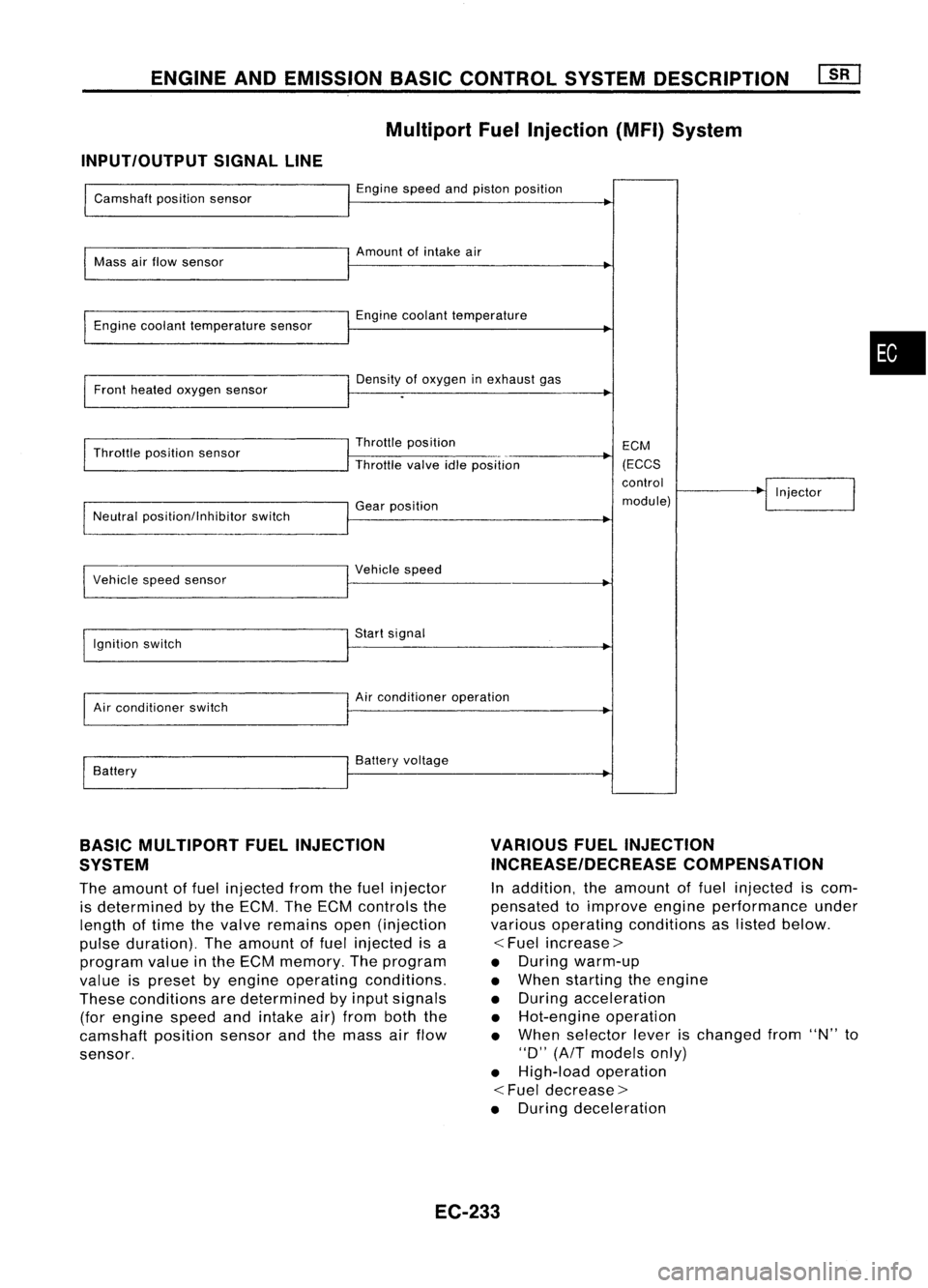
Multiport FuelInjection (MFI)System
INPUT/OUTPUT SIGNALLINE
Camshaft positionsensor
Mass airflow sensor
Engine coolant temperature sensor
Front heated oxygen sensor
Throttle position sensor
Neutral position/lnhibitor switch
I
Vehicle speedsensor
Ignition switch
Air conditioner switch
Battery Engine
speedandpiston position
Amount ofintake air
Engine coolant temperature
Density ofoxygen inexhaust gas
Throttle position
Throttle valveidleposition
Gear position
I
Vehicle speed
Start signal
Air conditioner operation
Battery voltage ECM
(ECCS
control
module) Injector
•
BASIC MULTIPORT FUELINJECTION
SYSTEM
The amount offuel injected fromthefuel injector
is determined bythe ECM. TheECM controls the
length oftime thevalve remains open(injection
pulse duration). Theamount offuel injected isa
program valueinthe ECM memory. Theprogram
value ispreset byengine operating conditions.
These conditions aredetermined byinput signals
(for engine speedandintake air)from boththe
camshaft positionsensorandthemass airflow
sensor.
VARIOUS
FUELINJECTION
INCREASE/DECREASE COMPENSATION
In addition, theamount offuel injected iscom-
pensated toimprove engineperformance under
various operating conditions aslisted below.
<
Fuel increase>
• During warm-up
• When starting theengine
• During acceleration
• Hot-engine operation
• When selector leverischanged from"N"to
"0" (AfT models only)
• High-load operation
<
Fuel decrease>
• During deceleration
EC-233
Page 982 of 1701
ON-BOARDDIAGNOSTIC SYSTEMDESCRIPTION
CONSULT (Cont'd)
REAL TIMEDIAGNOSIS INDATA MONITOR MODE
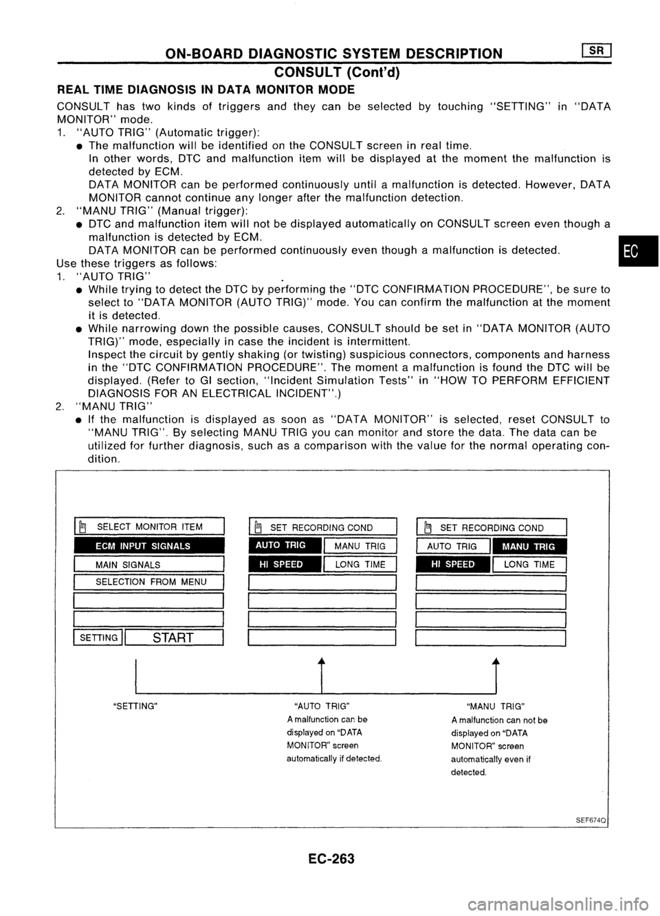
CONSULT hastwo kinds oftriggers andthey canbeselected bytouching "SETTING" in"DATA
MONITOR" mode.
1. "AUTO TRIG"(Automatic trigger):
• The malfunction willbeidentified onthe CONSULT screeninreal time.
In other words, DTCandmalfunction itemwillbedisplayed atthe moment themalfunction is
detected byECM.
DATA MONITOR canbeperformed continuously untilamalfunction isdetected. However, DATA
MONITOR cannotcontinue anylonger afterthemalfunction detection.
2. "MANU TRIG"(Manual trigger):
• DTC andmalfunction itemwillnotbedisplayed automatically onCONSULT screeneventhough a
malfunction isdetected byECM. •
DATA MONITOR canbeperformed continuously eventhough amalfunction isdetected.
Use these triggers asfollows:
1. "AUTO TRIG"
• While trying todetect theDTC byperforming the"DTC CONFIRMATION PROCEDURE",besure to
select to"DATA MONITOR (AUTOTRIG)" mode.Youcanconfirm themalfunction atthe moment
it is detected .
• While narrowing downthepossible causes,CONSULT shouldbeset in"DATA MONITOR (AUTO
TRIG)" mode,especially incase theincident isintermittent.
Inspect thecircuit bygently shaking (ortwisting) suspicious connectors, components andharness
in the "DTC CONFIRMATION PROCEDURE".Themoment amalfunction isfound theDTC willbe
displayed. (RefertoGI section, "Incident Simulation Tests"in"HOW TOPERFORM EFFICIENT
DIAGNOSIS FORANELECTRICAL INCIDENT".)
2. "MANU TRIG"
• Ifthe malfunction isdisplayed assoon as"DATA MONITOR" isselected, resetCONSULT to
"MANU TRIG".Byselecting MANUTRIGyoucan monitor andstore thedata. Thedata canbe
utilized forfurther diagnosis, suchasacomparison withthevalue forthe normal operating con-
dition.
ECM INPUT SIGNALS
HISPEED
AUTO
TRIG
I
~
SELECT MONITOR ITEM
I
MAIN SIGNALS
I
SELECTION FROMMENU
1 _
1========
l-SE-TI-IN-G
ll--S-T.-AR-T--
I
~
SET RECORDING COND
I
MANU TRIG
I
LONG TIME HI
SPEED MANU
TRIG
__ 1__ J
"SETIING" "AUTOTRIG"
A malfunction canbe
displayed on"DATA
MONITOR" screen
automatically ifdetected.
EC-263 "MANU
TRIG"
A malfunction cannotbe
displayed on"DATA
MONITOR" screen
automatically evenif
detected.
SEF6740
Page 989 of 1701
TROUBLEDIAGNOSIS -General Description
Fail-Safe Chart
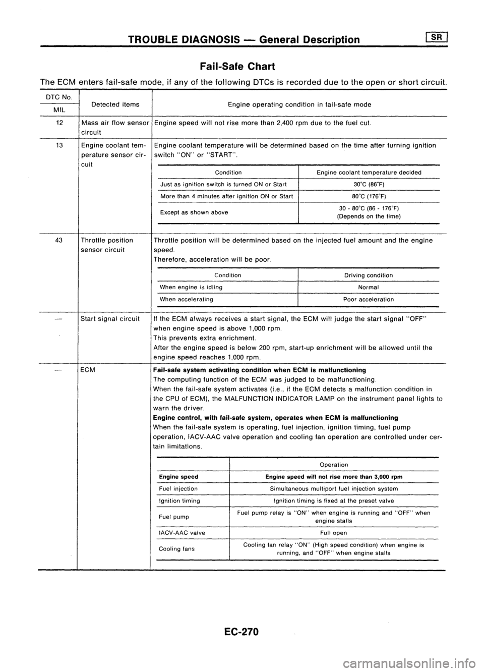
The ECM enters fail-safe mode,ifany ofthe following DTCsisrecorded duetothe open orshort circuit.
DTC No.
Detected items Engineoperating conditioninfail-safe mode
MIL
12 Massairflow sensor Enginespeedwillnotrise more than2,400 rpmduetothe fuel cut.
circuit
13 Enginecoolant tem-Engine coolant temperature willbedetermined basedonthe time after turning ignition
perature sensorcir-switch "ON"or"START".
cuit ConditionEnginecoolant temperature decided
Just asignition switchisturned ONorStart 30'C(86'F)
More than4minutes afterignition ONorStart 80'C(176'F)
Except asshown above 30
-80'C (86-176'F)
(Depends onthe time)
43 Throttle position
Throttleposition willbedetermined basedonthe injected fuelamount andtheengine
sensor circuit
speed.
Therefore, acceleration willbepoor.
Condition Drivingcondition
When engine i$idling
Normal
When accelerating Pooracceleration
-
Start
signal circuit
If
the ECM always receives astart signal, theECM willjudge thestart signal "OFF"
when engine speedisabove 1,000rpm.
This prevents extraenrichment.
After theengine speedisbelow 200rpm, start-up enrichment willbeallowed untilthe
engine speedreaches 1,000rpm.
-
ECM
Fail-safesystemactivating conditionwhenECMismalfunctioning
The computing functionofthe ECM wasjudged tobe malfunctioning.
When thefail-safe systemactivates (i.e.,ifthe ECM detects amalfunction conditionin
the CPU ofECM), theMALFUNCTION INDICATORLAMPonthe instrument panellightsto
warn thedriver.
Engine control, withfail-safe system,operates whenECMismalfunctioning
When thefail-safe systemisoperating, fuelinjection, ignitiontiming,fuelpump
operation, IACV-AACvalveoperation andcooling fanoperation arecontrolled undercer-
tain limitations.
Operation
Engine speed Enginespeedwillnotrise more than3,000 rpm
Fuel injection
Simultaneousmultiportfuelinjection system
Ignition timing Ignitiontimingisfixed atthe preset valve
Fuel pump Fuel
pump relayis"ON" whenengine isrunning and"OFF" when
engine stalls
IACV-AAC valve
Fullopen
Cooling fans Cooling
fanrelay "ON" (Highspeed condition) whenengine is
running, and"OFF" whenengine stalls
EC-270