Page 26 of 1701
TROUBLEDIAGNOSES
Pressure Testing
• Location ofpressure testport.
• Always replace pressure plugsasthey areself-sealing
bolts.
Test portfor
line pressure governor
pressure
SAT565D
LINEPRESSURE TESTPROCEDURE
1. Check AfTand engine fluidlevels. Ifnecessary, addfluid.
2. Drive vehicle forabout 10minutes untilengine oiland ATF
reach operating temperature.
ATF operating temperature:
50 -80°C (122-176°F)
SAT647B
3.Install pressure gaugetoline pressure port.
4. Set parking brakeandblock wheels.
Continue todepress brakepedalfullywhile performing line
pressure testatstall speed.
SAT513G
5.Start engine andmeasure linepressure atidle and stall
speed. Line pressure:
Refer toSOS, AT-166.
JUDGEMENT OFLINE PRESSURE TEST
• Ifline pressure doesnotrise, firstcheck tomake surethat
throttle wireisconnected properly.
1) When linepressure whileidling
is
low atall positions ("D",
"2", "1", "R"and"P"), theproblem maybedue to:
SAT494G •
Wear oninterior ofoil pump
AT-26
Page 233 of 1701

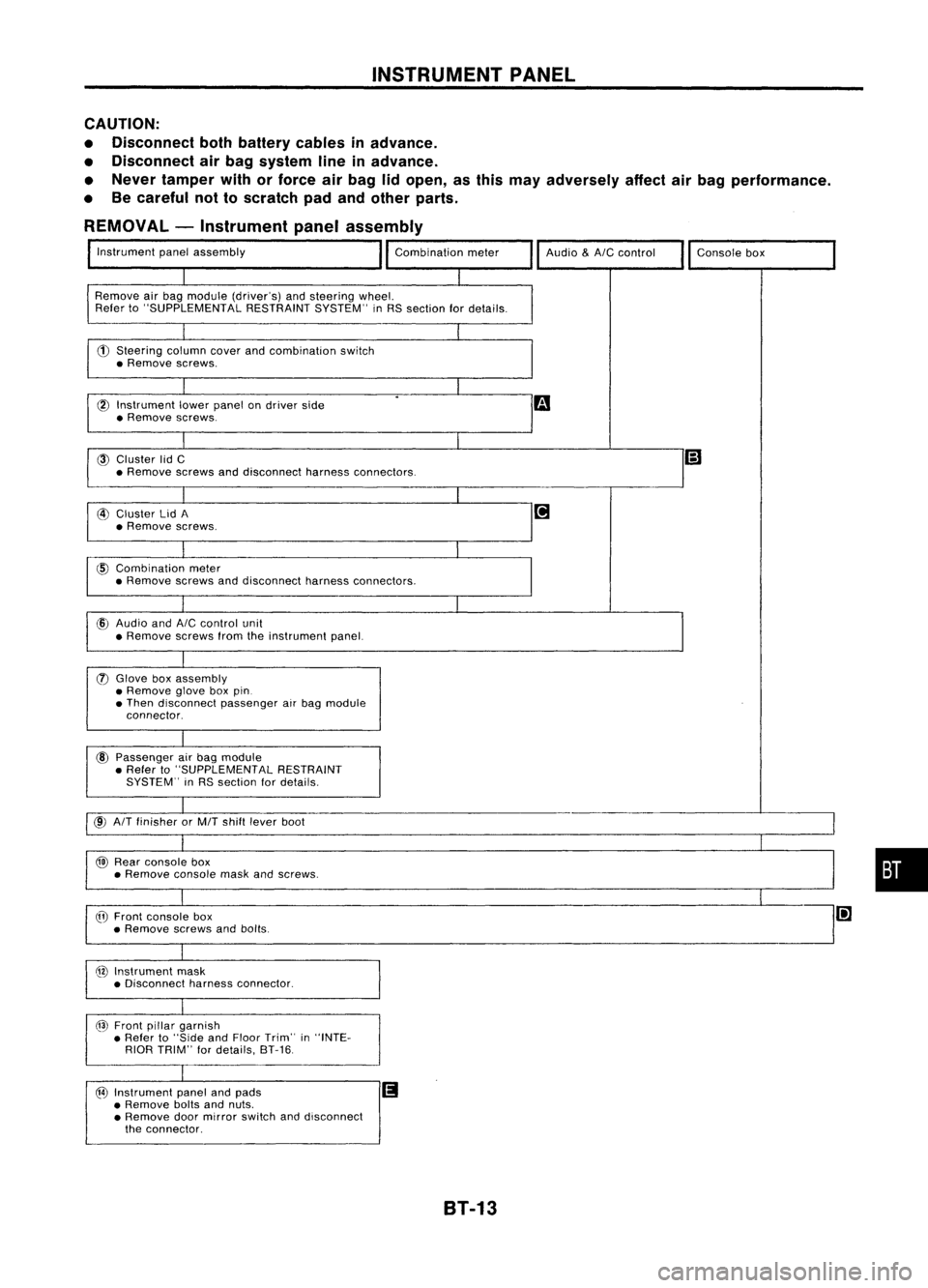
INSTRUMENTPANEL
CAUTION:
• Disconnect bothbattery cablesinadvance.
• Disconnect airbag system lineinadvance.
• Never tamper withorforce airbag lidopen, asthis may adversely affectairbag performance.
• Becareful nottoscratch padandother parts.
REMOVAL -Instrument panelassembly
Instrument panelassembly
Remove airbag module (driver's) andsteering wheel.
Refer to"SUPPLEMENTAL RESTRAINTSYSTEM"inRS section fordetails.
CD
Steering columncoverandcombination switch
• Remove screws.
l6l
Instrument lowerpanel ondriver side
• Remove screws.
@
Cluster lidC
• Remove screwsanddisconnect harnessconnectors. Audio
&AIC
control
Consolebox
@
Cluster lidA
• Remove screws.
@
Combination meter
• Remove screwsanddisconnect harnessconnectors.
cID
Audio and
AIC
control unit
• Remove screwsfromtheinstrument panel.
(J)
Glove boxassembly
• Remove gloveboxpin.
• Then disconnect passengerairbag module
connector.
@
Passenger airbag module
• Refer to"SUPPLEMENTAL RESTRAINT
SYSTEM" inRS section fordetails.
@
AIT
finisher orMIT shift lever boot
@
Rear console box
• Remove consolemaskandscrews.
@
Front console box
• Remove screwsandbolts.
@
Instrument mask
• Disconnect harnessconnector.
@
Front pillargarnish
• Refer to"Side andFloor Trim" in"INTE-
RIOR TRIM" fordetails, 8T-16.
@
Instrument panelandpads
II
• Remove boltsandnuts.
• Remove doormirror switch anddisconnect
the connector.
•
8T-13
Page 296 of 1701
Bolts
(M8
x
1.25) Wheel
cylinder
Adjuster
SBR280B
SBR020A REAR
DRUM BRAKE
Removal (Cont'd)
1. Release parkingbrakeleverfully,thenremove drum.
If drum ishard toremove, thefollowing procedures shouldbe
carried out.
a. Remove plug.Thenshorten adjuster tomake clearance
between brakeshoeanddrum asshown.
b. Tighten thetwo bolts gradually.
SBR785BA
2.
After removing retainer,removespringbyrotating shoes.
• Becareful nottodamage wheelcylinder pistonboots.
• Becareful nottodamage parkingbrakecablewhensepa-
rating it.
3. Remove adjuster.
4. Disconnect parkingbrakecablefromtoggle lever.
5. Remove retainerringwith asuitable tool.Then separate
toggle leverandbrake shoe.
Inspection -Wheel Cylinder
• Check wheelcylinder forleakage.
• Check forwear, damage andloose conditions.
Replace ifany such condition exists.
BR-26
Page 370 of 1701

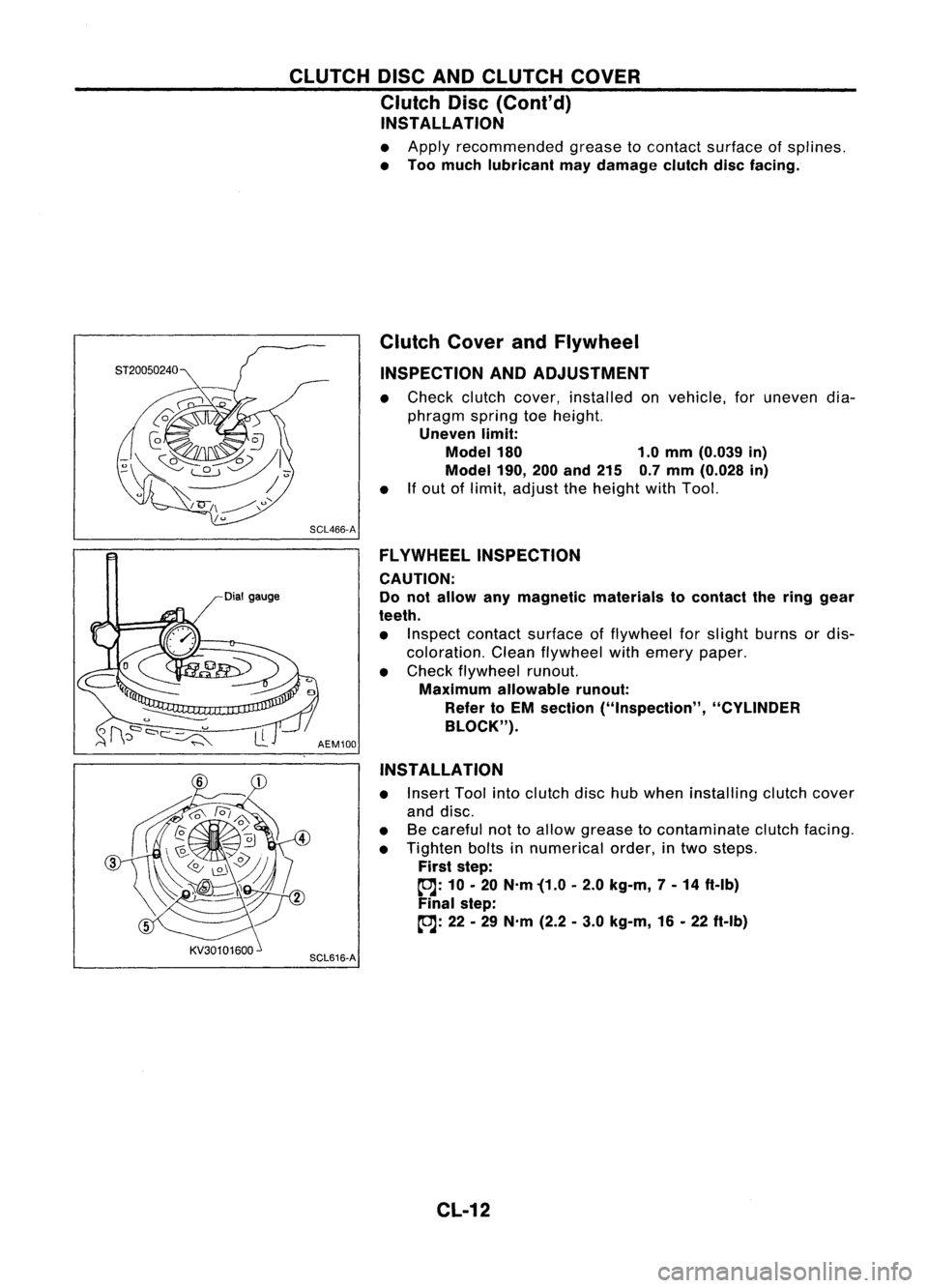
CLUTCHDISCANDCLUTCH COVER
Clutch Disc(Cont'd)
INSTALLATION
• Apply recommended greasetocontact surface ofsplines.
• Too much lubricant maydamage clutchdiscfacing.
Dial gauge Clutch
CoverandFlywheel
INSPECTION ANDADJUSTMENT
• Check clutchcover, installed onvehicle, foruneven dia-
phragm springtoeheight.
Uneven limit:
Model 180 1.0mm (0.039 in)
Model 190,
200and 215 0.7mm (0.028 in)
• Ifout oflimit, adjust theheight withTool.
SCL466-A FLYWHEEL INSPECTION
CAUTION:
Do not allow anymagnetic materials tocontact thering gear
teeth.
• Inspect contact surface offlywheel forslight burns ordis-
coloration. Cleanflywheel withemery paper.
• Check flywheel runout.
Maximum allowable runout:
Refer toEM section ("Inspection", "CYLINDER
BLOCK").
AEM100
INSTALLATION
• Insert Toolintoclutch dischubwhen installing clutchcover
and disc.
• Becareful nottoallow grease tocontaminate clutchfacing.
• Tighten boltsinnumerical order,intwo steps.
First step:
~: 10•20 N'm '(1.0 •2.0 kg-m, 7-14 ft-Ib)
Final step:
~: 22•29 N'm (2.2•3.0 kg-m, 16•22 ft-Ib)
SCL616-A
CL-12
Page 687 of 1701

SMA525AON-VEHICLE
SERVICE
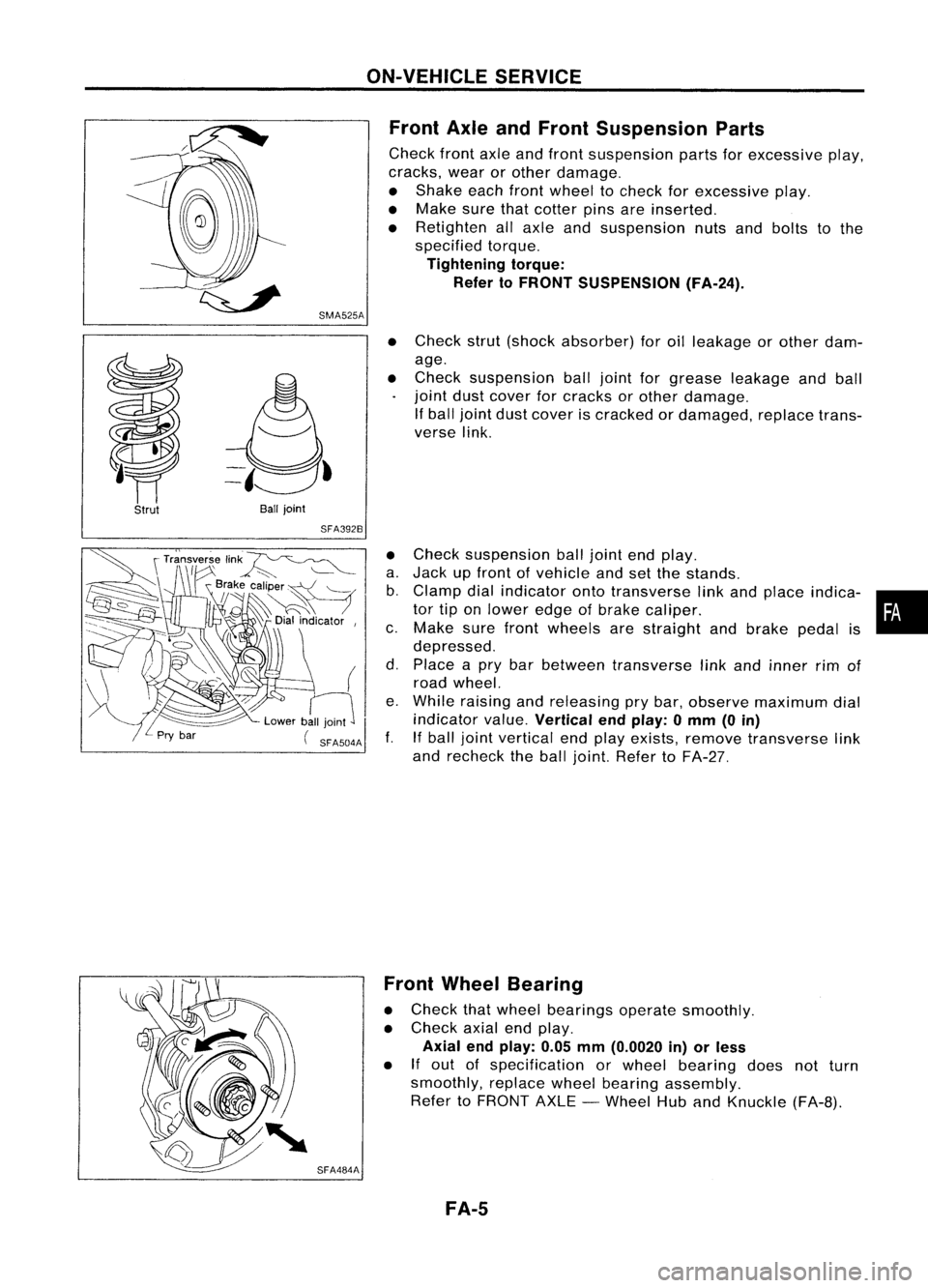
Front AxleandFront Suspension Parts
Check frontaxleandfront suspension partsforexcessive play,
cracks, wearorother damage.
• Shake eachfrontwheel tocheck forexcessive play.
• Make surethatcotter pinsareinserted.
• Retighten allaxle andsuspension nutsandbolts tothe
specified torque.
Tightening torque:
Refer toFRONT SUSPENSION (FA-24).
Strut
Ball
joint
SFA392B
•
Check strut(shock absorber) foroilleakage orother dam-
age.
• Check suspension balljoint forgrease leakage andball
joint dustcover forcracks orother damage.
If ball joint dustcover iscracked ordamaged, replacetrans-
verse link.
• Check suspension balljoint endplay.
a. Jack upfront ofvehicle andsetthe stands.
b. Clamp dialindicator ontotransverse linkand place indica- •
tor tiponlower edgeofbrake caliper. •
c. Make surefront wheels arestraight andbrake pedalis
depressed.
d. Place apry bar between transverse linkand inner rimof
road wheel.
e. While raising andreleasing prybar, observe maximum dial
indicator value.
Vertical endplay: 0mm (0in)
f. Ifball joint vertical endplay exists, remove transverse link
and recheck theball joint. Refer toFA-27.
SFA484A Front
Wheel Bearing
• Check thatwheel bearings operatesmoothly.
• Check axialendplay.
Axial endplay: 0.05mm(0.0020 in)orless
• If
out ofspecification orwheel bearing doesnotturn
smoothly, replacewheelbearing assembly.
Refer toFRONT AXLE-Wheel HubandKnuckle (FA-B).
FA-5
Page 691 of 1701
SFA113AASFA114A
FRONT
AXLE
Wheel HubandKnuckle (Conl'd)
3. Separate tie-rodfromknuckle withTool.
Install studnutonstud bolttoprevent damage tostud bolt.
4. Separate driveshaftfrom knuckle bylightly tapping it.Ifit
is hard toremove, useapuller.
Cover bootswithshop towel soas not todamage themwhen
-removing driveshaft.
5. Remove strutlower mounting bolts.
6. Loosen lowerballjoint tightening nut.
7. Separate knucklefromlower balljoint studwithTool.
8. Remove knucklefromtransverse link.
INSTALLATION
1. Install knuckle withwheel hub.
• Replace strutlower mounting nuts.
When installing knuckletostrut, besure tohold bolts and
tighten nuts.
~: 114-133 N'm (11.6 •13.6 kg-m, 84.98 ft.lb)
Before tightening, applyoiltothreaded portionofdrive shaft
and both sides ofplain washer.
2. Tighten wheelbearing locknut.
~: 196-275 N'm (20•28 kg-m, 145-203 ft-Ib)
FA-9
•
Page 694 of 1701
Wheelbearing
assembly SFA953A
SFA090A
FRONT
AXLE
Wheel HubandKnuckle (Cont'd)
5. Install innergrease seal.
Maximum loadP:
10 kN (1ton, 1.1USton, 1.0Imp ton)
6. Press wheel hubinto knuckle.
Maximum loadP:
29 kN (3ton, 3.3USton, 3.0Imp ton)
Be careful nottodamage greaseseal.
7. Check bearing operation.
a. Add load Pwith press.
Load P:
34.3 -49.0 kN(3.5 -5.0 ton, 3.9-5.5 USton,
3.44 •4.92 Impton)
b. Spin knuckle severalturnsinboth directions.
c. Make surethatwheel bearings operatesmoothly.
Drive Shaft
REMOVAL
1. Remove wheelbearing locknut.
Brake caliper neednotbedisconnected.
Do not twist orstretch brakehosewhen moving components.
SFA1538
2.
Remove strutlower mounting bolts.
3. Remove brakehoseclip.
FA-12
Page 709 of 1701

View
from
B FRONT
SUSPENSION
Stabilizer Bar(Cont'd)
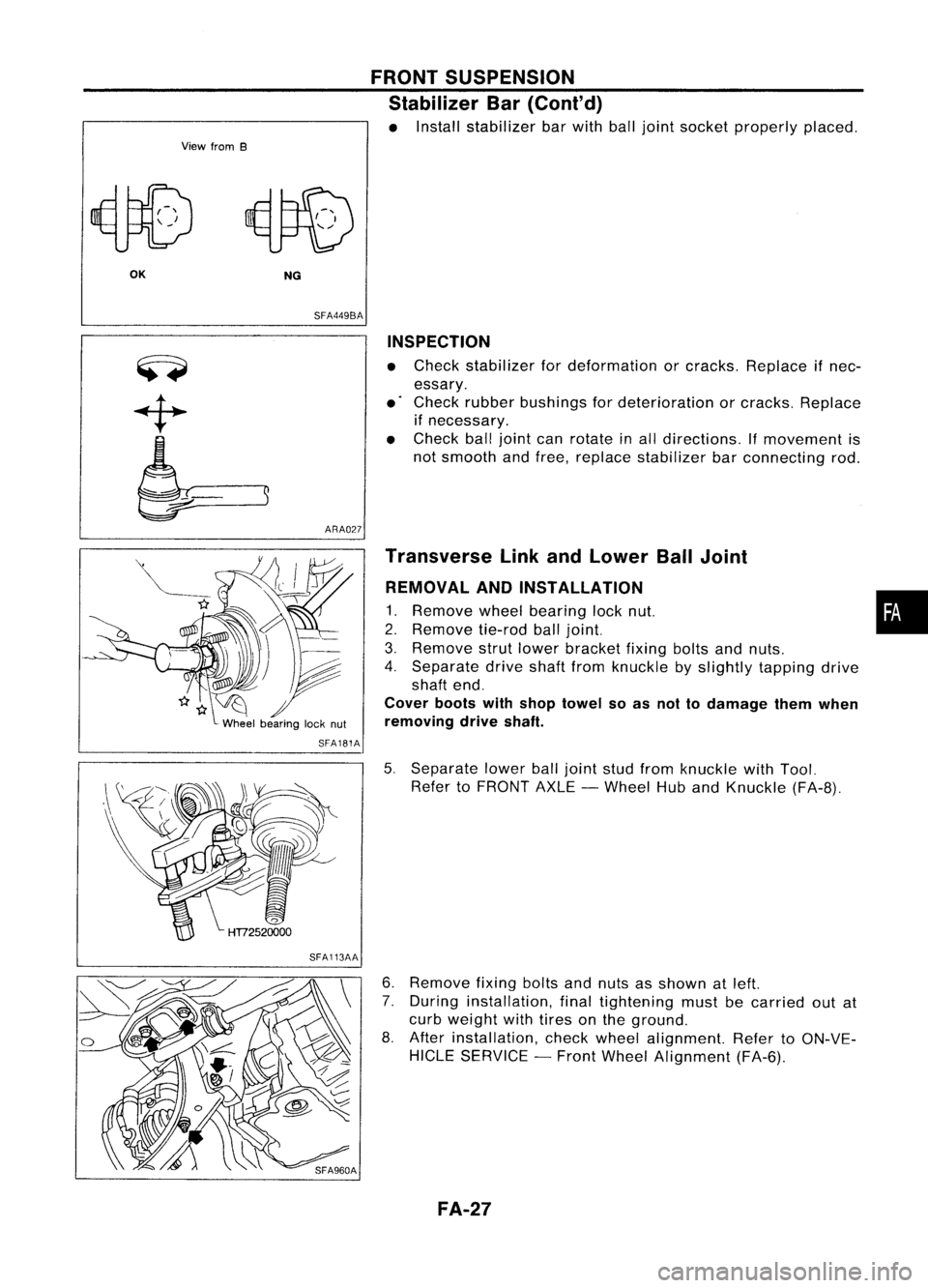
• Install stabilizer barwith balljoint socket properly placed.
OK NG
SFA449BA
ARA027 INSPECTION
• Check stabilizer fordeformation orcracks. Replace ifnec-
essary.
• Check rubber bushings fordeterioration orcracks. Replace
if necessary.
• Check balljoint canrotate inall directions. If
movement
is
not smooth andfree, replace stabilizer barconnecting rod.
SFA181A
SFA113AA Transverse
LinkandLower BallJoint
REMOVAL ANDINSTALLATION
1. Remove
wheelbearing locknut. •
2. Remove
tie-rodballjoint.
3. Remove
strutlower bracket fixingboltsandnuts.
4. Separate driveshaftfromknuckle byslightly tapping drive
shaft end.
Cover bootswithshop towel soas not todamage themwhen
removing driveshaft.
5. Separate lowerballjoint studfrom knuckle withTool.
Refer toFRONT AXLE-Wheel HubandKnuckle (FA-8).
6. Remove
fixingboltsandnuts asshown atleft.
7. During installation, finaltightening mustbecarried outat
curb weight withtires onthe ground.
8. After installation, checkwheel alignment. RefertoON-VE-
HICLE SERVICE -Front Wheel Alignment (FA-6).
FA-27