Page 375 of 1701

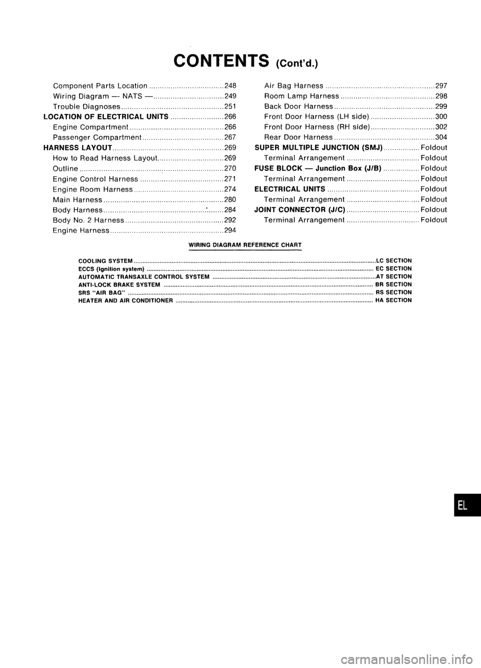
CONTENTS(Cont'd.)
Component PartsLocation 248
Wiring Diagram -NATS - 249
Trouble Diagnoses 251
LOCATION OFELECTRICAL UNITS
266
Engine Compartment 266
Passenger Compartment 267
HARNESS LAyOUT
269
How toRead Harness Layout... 269
Outline 270
Engine Control Harness 271
Engine RoomHarness 274
Main Harness '" 280
Body Harness :284
Body No.2 Harness 292
Engine Harness 294Air
Bag Harness 297
Room LampHarness 298
Back DoorHarness 299
Front DoorHarness (LHside) 300
Front DoorHarness (RHside) 302
Rear Door Harness 304
SUPER MULTIPLE JUNCTION
(SMJ) Foldout
Terminal Arrangement Foldout
FUSE BLOCK -Junction Box
(JIB)
Foldout
Terminal Arrangement Foldout
ELECTRICAL UNITS
Foldout
Terminal Arrangement Foldout
JOINT CONNECTOR
(J/C)
Foldout
Terminal Arrangement Foldout
WIRING DIAGRAM REFERENCE CHART
COOLING SYSTEM
LC
SECTION
ECCS (Ignition syslem) ECSECTION
AUTOMATIC TRANSAXLECONTROLSYSTEM ATSECTION
ANTI-LOCK BRAKESYSTEM BRSECTION
SRS "AIR BAG" RSSECTION
HEATER ANDAIRCONDITIONER HASECTION
•
Page 569 of 1701

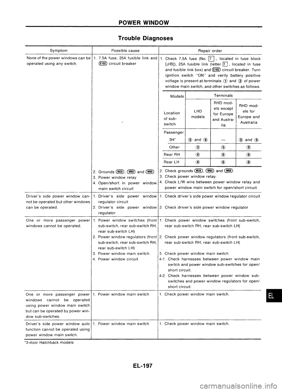
POWERWINDOW
Trouble Diagnoses
None ofthe power windows canbe1.7.5A fuse, 25Afusible linkand 1.
operated usinganyswitch. ~circuit breaker
Symptom
Possiblecause
Repairorder
Check 7.5Afuse(No.
12J,
located infuse block
[J/B)), 25Afusible link(letter [[],located infuse
and fusible linkbox) and~ circuit breaker. Turn
ignition switch"ON"andverify battery positive
voltage ispresent atterminals
CD
and @ofpower
window mainswitch, andother switches asfollows.
Models Terminals
Location
of sub-
switch LHD
models RHD
mod-
els except
for Europe
and Austra-
lia RHD
mod-
els for
Europe and
Australia
Passenger 3H*
@
and @
-
@
and @
Other
@@
@
Rear RH @
@
@
Rear LH @
@@
Check grounds
@,~
and
@ill.
Check powerwindow relay.
Check LlWwire between powerwindow relayand
power window mainswitch foropen/short circuit.
2.
3.
window 4.
2.
Grounds
@,~
and
@ill
3. Power window relay
4. Open/short inpower
main switch circuit
Driver's sidepower window can-1.Driver's sidepower window 1.Check driver's sidepower window regulator circuit
not beoperated butother windows regulatorcircuit
can beoperated. 2.Driver's sidepower window 2.Check driver's sidepower window regulator
regulator
•
1.
Check powerwindow switches (frontsub-switch,
rear sub-switch RH,rear sub-switch LH)
2. Check power window regulators (frontsub-switch,
rear sub-switch RH,rear sub-switch LH)
3. Check powerwindow mainswitch
4-1. Check harnesses betweenpowerwindow main
switch andpower window sub-switches foropen/
short circuit.
4-2. Check harnesses betweenpowerwindow sub-
switches andpower window regulators foropen/
short circuit.
1. Check powerwindow mainswitch.
Power
window switches (front
sub-switch, rearsub-switch RH,
rear sub-switch LH)
2. Power window regulators (front
sub-switch, rearsub-switch RH,
rear sub-switch LH)
3. Power window mainswitch
4. Power window circuit
One
ormore passenger power1.
windows cannotbeoperated.
One ormore passenger power1.Power window mainswitch
windows cannotbeoperated
using power window mainswitch
but can beoperated bypower win-
dow sub-switches.
Driver's sidepower window auto1.Power window mainswitch
function cannotbeoperated using
power window mainswitch. 1.
Check powerwindow mainswitch.
*3-door Hatchback models
EL-197
Page 638 of 1701
LOCATIONOFELECTRICAL UNITS
Engine Compartment
Front wiper motor (LHDmodels)
Fusible linkand relay box ASS
relay boxand actuator (RHOmodels)
Front wiper motor (RHOmodels)
Glow relay(CDengine models)
Fusible linkand fuse box
Cooling fan
relay-2 Rear
foglamp relay
• Cooling fanrelay-3 (SRengine
AT models andCDengine)
Rear window defogger relay
(GA engine withdaytime lightsystem)
EL-266 Fusible
linkand fuse box
Fusible linkand relay box
Rear window defogger relay
(CD engine withdaytime lightsystem)
HEL149
Page 639 of 1701
LOCATIONOFELECTRICAL UNITS
Passenger Compartment
LHD MODELS
Rearwindow defogger timer
(With daytime lightsystem)
Warning buzzerunit
Combination flasherunit
Junction boxNO.2 (Joint connectors)
Stop lamp switch
Mirror defogger relay
(With daytime lightsystem)
Sun roofrelay (Without powerwindow)
Power window relay(With power window)
Front foglamp relay
SMJ (Main harness-
engine roomharness) NATS
IMMU (Gasoline engine)
Door locktimer
ABS control unit
Front wiper amplifier
SMJ (Main harness-
front doorharness)
SMJ (Main harness-
front doorharness)
Rear wiper amplifier
Daytime lightunit
Circuit breaker
Fuel pump relay
(Gasoline engine)
Fuse block
(JIB)
Ignition relay
Blower relay
Accessory relay Air
bag diagnosis sensorunit
(With dualairbag system)
ECM (ECCS control module) (Gasoline engine)
ECM (Engine controlmodule) (Dieselengine)
ECCS relay(Gasoline engine)
EL-267 HEL
150
•
Page 1365 of 1701

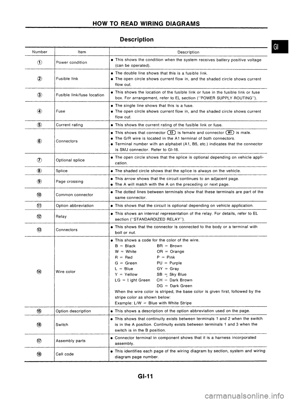
HOWTOREAD WIRING DIAGRAMS
Description
Number Item Description
CD
Power
condition •
This shows thecondition whenthesystem receives batterypositive voltage
(can beoperated) .
• The double lineshows thatthisisafusible link.
@
Fusiblelink
•The open circle shows current flowin,and theshaded circleshows current
flow out.
Fusible
link/fuse location •
This shows thelocation ofthe fusible linkorfuse inthe fusible linkorfuse
box. Forarrangement, refertoEL section ("POWER SUPPLYROUTING") .
• The single lineshows thatthisisafuse.
@
Fuse
•The open circle shows current flowin,and theshaded circleshows current
flow out.
CID
Current
rating
•This shows thecurrent ratingofthe fusible linkorfuse .
• This shows thatconnector
@)
isfemale andconnector
@
ismale .
@
Connectors •
The G/R wire islocated inthe A1 terminal ofboth connectors.
• Terminal numberwithanalphabet (A1, B5, etc.) indicates thattheconnector
is SMJ connector. RefertoGI-16 .
rJ)
Optionalsplice •
The open circle shows thatthesplice isoptional depending onvehicle appli-
cation.
@
Splice •The shaded circleshows thatthesplice isalways onthe vehicle.
@
Page
crossing •
This arrow shows thatthecircuit continues toan adjacent page.
• The Awill match withtheAon the preceding ornext page .
@)
Commonconnector •
The dotted linesbetween terminals showthatthese terminals arepart ofthe
same connector.
@
Option
abbreviation •This shows thatthecircuit isoptional depending onvehicle application.
@
Relay •
This shows aninternal representation ofthe relay. Fordetails, refertoEL
section ("STANDARDIZED RELAY").
@
Connectors •
This shows thattheconnector isconnected tothe body oraterminal with
bolt ornut.
• This shows acode forthe color ofthe wire.
B
=
Black BR
=
Brown
W
=
White OR
=
Orange
R
=
Red P
=
Pink
G
=
Green PU
=
Purple
@
Wire
color L
=
Blue GY
=
Gray
Y
=
Yellow SB
=:
Sky Blue
LG
=
Light Green CH
=
Dark Brown
DG
=
Dark Green
When thewire color isstriped, thebase color isgiven first,followed bythe
stripe colorasshown below:
Example: LlW
=
Blue withWhite Stripe
@
Optiondescription •
This shows adescription ofthe option abbreviation usedonthe page.
• This shows thatcontinuity existsbetween terminals 1and 2when theswitch
@)
Switch is
inthe Aposition. Continuity existsbetween terminals 1and 3when the
switch isinthe Bposition .
@
Assembly
parts •
Connector terminalincomponent showsthatitis aharness incorporated
assembly .
@
Cell
code •
This identifies eachpage ofthe wiring diagram bysection, systemandwiring
diagram pagenumber.
GI-11
•