Page 509 of 1701
METERANDGAUGES
Fuel Tank Gauge UnitCheck
• For removal, refertoFE section ("FUEL SYSTEM").
Check theresistance betweenterminals (G)and (E).
*1 and '3:When floatrodisin contact withstopper.
Thermal Transmitter Check
Check theresistance betweentheterminals ofthermal trans-
mitter andbody ground.
Ohmmeter
Resistance
Float position mm(in) value
(+)
H
(0)
'3 Full 36
(1.42) Approx.4-6
G E
'2 1/2
86(3.39) 27-35
'1 Empty
131(5.16) 78-85
Approx. 70-90Q
Approx. 21-24Q
Resistance
60'G (140'F)
100'G (212'F)
Water
temperature
'1
MEL622D
Ohmmeter
~- SEL233P
~ Vehiclespeed
~ ~sensor
~y<
Voltmeter {/l
[Y]
Approx. O.5V
[Alternating
current (AG)] Vehicle
SpeedSensor SignalCheck
1. Remove vehiclespeedsensor fromtransaxle.
2. Turn speedometer pinionquickly andmeasure voltage
across
CD
and ~.
SEL840T
•
EL-137
Page 716 of 1701
Connector
/
SFE145A
t2Front
SFE366AFUEL
SYSTEM
Fuel Pump andGauge
REMOVAL
1. Release fuelpressure fromfuelline.
Refer toEC section ("FuelPressure Release", "BASICSER-
VICE PROCEDURE").
2. Remove inspection holecover located undertherear seat.
3. Disconnect fueloutlet, returntubeandconnectors.
4. Remove thesixscrews.
5. Remove fuelgauge assembly anddisconnect tubesand
connector.
6. Remove fuelpump withfueltank chamber asshown inthe
figure.
a. Pull upthe front offuel pump.
b. Slide itforward.
Fuel pump harness
Fuel pump
SFE366A
7.
Remove fueltank chamber fromfuelpump.
INSTALLATION
To install, reverse theremoval procedure.
CAUTION:
• Tighten tospecified torque.
• Install fuelpump harness onthe leftside ofthe feed hose
as shown inthe figure.
FE-4
Page 1224 of 1701

ENGINEREMOVAL
WARNING:
a. Situate vehicle onaflat and solid surface.
b. Place chocks atfront andback ofrear wheels.
c. Donot remove engineuntilexhaust systemhascompletely
cooled off.
Otherwise, youmay burn yourself and/orfiremay break out
in fuel line.
d. For safety during subsequent steps,thetension ofwires
should beslackened againsttheengine.
e. Before disconnecting fuelhose, release fuelpressure from
fuel line.
Refer to"Releasing FuelPressure" inEC section.
f. Besure tohoist engine andtransaxle inasafe manner.
g. For engines notequipped withengine slingers, attach
proper slingers andbolts described inPARTS CATALOG.
CAUTION:
• When liftingengine, besure toclear surrounding parts.
Take special careforaccelerator wirecasing, brakelines
and brake master cylinder.
• Inhoisting theengine, alwaysuseengine slingers inasafe
manner.
• Inremoving driveshaft, becareful nottodamage grease
seal oftransaxle.
Engine cannotberemoved separately fromtransaxle. Remove
engine withtransaxle.
Removal
1. Drain water.
2. Remove hood.
3. Remove battery.
4. Remove reservoir tankandbracket.
5. Remove drivebelts.
6. Remove alternator, compressor andpower steering oil
pump fromengine.
Power steering pumpdoesnotneed tobe disconnected from
power steering tubes.
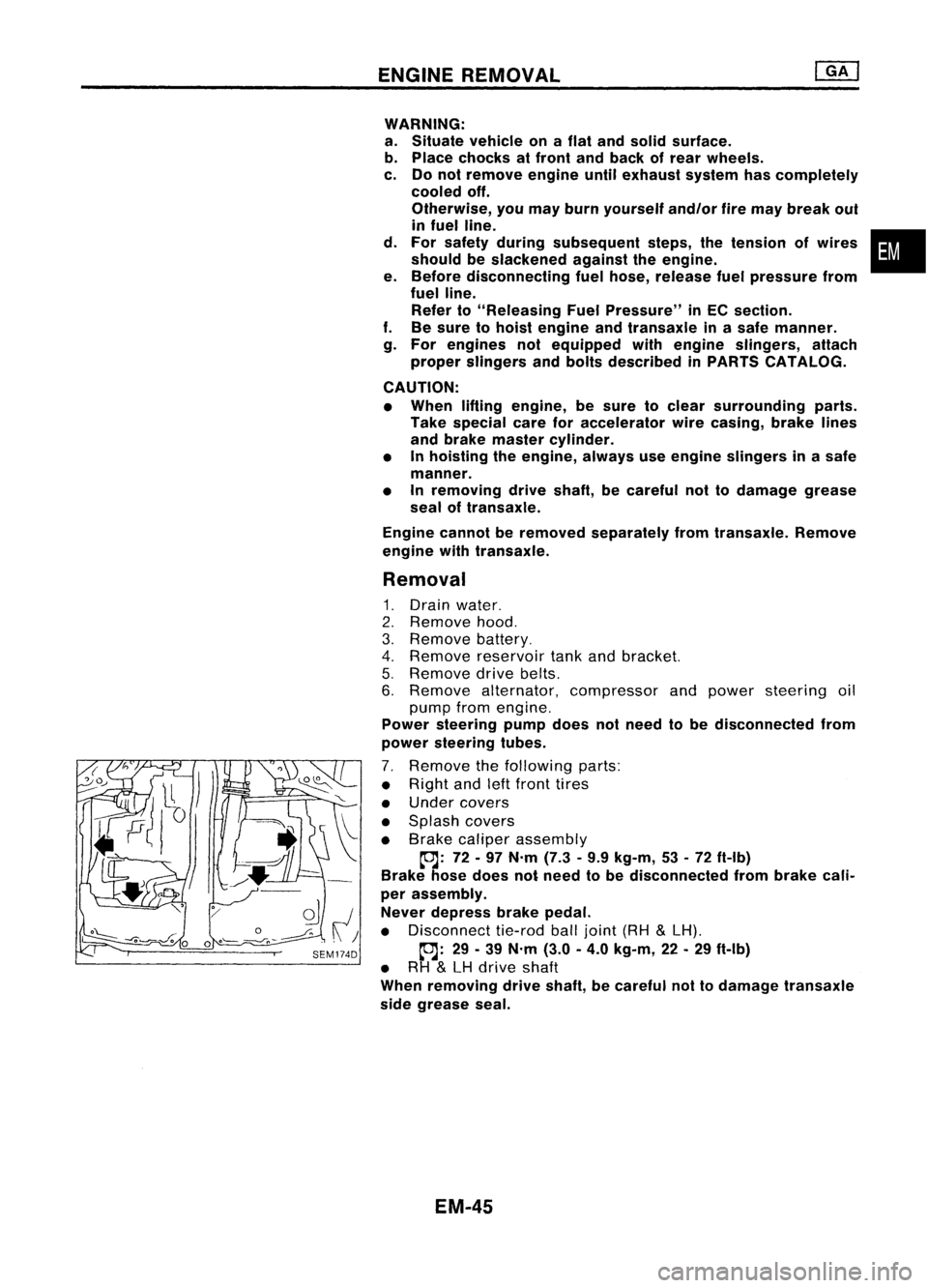
7. Remove thefollowing parts:
• Right andleftfront tires
• Under covers
• Splash covers
• Brake caliper assembly
~: 72-97 N'm (7.3•9.9 kg-m, 53•72 ft-Ib)
Brake hosedoes notneed tobe disconnected frombrake cali-
per assembly.
Never depress brakepedal.
• Disconnect tie-rodballjoint (RH
&
LH).
~: 29-39 N'm (3.0-4.0 kg-m, 22-29 ft-Ib)
• RH
&
LH drive shaft
When removing driveshaft, becareful nottodamage transaxle
side grease seal.
EM-45
•
Page 1359 of 1701

PRECAUTIONS
General Precautions (Cont'd)
• After disconnecting vacuumorair hoses, attachatag to
indicate theproper connection.
• Use only thefluids andlubricants specifiedinthis manual.
• Use approved bondingagent,sealants ortheir equivalents
when required.
• Use tools andrecommended specialtoolswhere specified
for safe andefficient servicerepairs.
• When repairing thefuel, oil,water, vacuum orexhaust
systems, checkallaffected linesforleaks.
• Dispose ofdrained oilorthe solvent usedforcleaning parts
in an appropriate manner.
Precautions forMultiport FuelInjection System
or ECCS Engine
• Before connecting ordisconnecting anyharness connector
for the multiport fuelinjection systemorEGM (EGGS control
module):
Turn ignition switchto"OFF" position.
Disconnect negativebatteryterminal.
Otherwise, theremaybedamage toEGM.
• Before disconnecting pressurizedfuellinefrom fuelpump to
injectors, besure torelease fuelpressure.
• Becareful nottojar components suchasEGM andmass air
flow sensor.
Precautions forThree WayCatalyst
If a large amount ofunburned fuelflows intothecatalyst, the
catalyst temperature willbeexcessively high.Toprevent this,
follow theinstructions below:
• Use unleaded gasolineonly.Leaded gasoline willseriously
damage thethree waycatalyst.
• When checking forignition sparkormeasuring engine
compression, maketestsquickly andonly when necessary.
• Donot run engine whenthefuel tank level islow, otherwise
the engine maymisfire causing damage tothe catalyst.
Do not place thevehicle onflammable material.Keepflamma-
ble material offthe exhaust pipeandthethree waycatalyst.
Engine Oils
Prolonged andrepeated contactwithused engine oilmay
cause skincancer. Trytoavoid direct skincontact withused oil.
If skin contact is.made, washthoroughly withsoap orhand
cleaner assoon aspossible.
HEALTH PROTECTION PRECAUTIONS
• Avoid prolonged andrepeated contactwithoils, particularly
used engine oils.
• Wear protective clothing,including impervious gloves
where practicable.
• Donot putoily rags inpockets.
• Avoid contaminating clothes,particularly underpants, with
oil.
• Heavily soiledclothing andoil-impregnated footwearshould
not beworn. Overalls mustbecleaned regularly.
• First Aidtreatment shouldbeobtained immediately foropen
cuts andwounds.
• Use barrier creams, applying thembefore eachwork
period, tohelp theremoval ofoil from theskin.
GI-5
•