Page 32 of 1701
SAT496HB
SAT700D ON-VEHICLE
SERVICE
Control ValveAssembly andAccumulator
(Cont'd)
6. Remove controlvalveassembly byremoving fixingbolts.
Bolt length, number andlocation:
Bolt symbol
@
@
CID
@
Bolt length" C"
25.033.040.0 43.5
~Q
mm(in)
(0.984)
(1.299)(1.575)
(1.713)
Number ofbolts
2652
Tightening torque
7-9 (0.7 -0.9, 61-78)
N'm (kg-m, in-Ib)
• Becareful nottodrop manual valve,tubeconnector, tubes
and 3.Raccumulator returnspring.
7. Disassemble andinspect controlvalveassembly ifneces-
sary -Refer to"REPAIR FORCOMPONENT PARTS",
AT-74.
SAT497H
8.
Remove 3-Rand N-Daccumulators byapplying compressed
air ifnecessary.
• Hold each piston witharag.
INSTALLATION
• Set manual shaftinNeutral position, thenalign manual
plate withgroove inmanual valve.
• After installing controlvalveassembly, makesurethat
selector levercanbemoved toall positions.
AT-32
Page 40 of 1701
REMOVALANDINSTALLATION
Installation
• Drive platerunout
Maximum allowablerunout:
Refer toEM section ("Inspection", "CYLINDER
BLOCK").
If this runout isout ofallowance, replacedriveplatewith
ring gear.
SAT037C
•When connecting torqueconverter totransaxle, measure
distance "A"tobe certain thatthey arecorrectly assem-
bled.
Distance
"A":
Except model34X81
21.1 mm(0.831 in)ormore
Model 34X81
15.9 mm(0.626 in)ormore
o
AIT
toengine
o
Engine (gusset)
to
AIT
SAT573D
•Install converter todrive plate.
• With converter installed,rotatecrankshaft severalturnsto
check thattransaxle rotatesfreelywithout binding.
• Tighten boltsfixing transaxle
GA engine models
Bolt No. Tightening
torque Boltlength
"e"
N.m (kg-m, ft-Ib) mm
(in)
G)
30-40 (3.1 -4.1,22 -30) 50
(1.97)
@ .30-40 (3.1 -4.1, 22-30) 30
(1.18)
@ 16
-21 (1.6 -2.1,12 -15) 25
(0.98)
Front gusset to
30-40 (3.1 -4.1,22 -30) 20
(0.79)
engine
Rear gusset to
16-21 (1.6 -2.1,12 -15) 16
(0.63)
engine
AT-40
Page 41 of 1701
Boltlength
'T'
mm (in)
55 (2.17)
50 (1.97)
65 (2.56)
25 (0.98)
40 (1.57)
Tightening
torque
N'm (kg-m, ft-Ib)
70 -79 (7.1 -8.1,51 -59)
70 -79 (7.1 -8.1, 51-59)
70 -79 (7.1 -8.1,51 -59)
30 -40 (3.1 -4.1, 22-30)
30 -40 (3.1 -4.1, 22-30)
CD
@
@
@
@
Bolt
No.
• Reinstall anypart removed.
• Adjust throttle wireandcontrol cable.Referto"ON-VEHI-
CLE SERVICE", AT-33,35.
•. Check inhibitor switch.Referto"Electrical Components
Inspection", AT-3D.
• Refill transaxle withATFandcheck fluidlevel, AT-17.
• Move selector leverthrough allpositions tobe sure that
transaxle operatescorrectly. Withparking brakeapplied,
idle engine. Moreselector leverthrough "N"to"D", to"2",
to "1" and "R". Aslight shock should befelt through the
hand gripping theselector eachtimethetransaxle is
shifted. •
• Perform roadtest-Refer to"ROAD TESTING", AT-17.
i
REMOVAL
ANDINSTAllATION
Installation (Cont'd)
SR engine models
SAT638A
SAT558DA
AIT
toengine
@
Engine to
AIT
AT-41
Page 53 of 1701
('l:,~~
o
\~A~~l
o
u~!~~:
Contact
0
9
&k .~
'"~~~~~)(?~~
SIR
accumulator piston ~./
SAT023DB
SAT129E
SAT024D DISASSEMBL
Y
14. Remove N-Daccumulator pistonandreturn spring with
compressed air.
15. Remove O-ringsfromN-Daccumulator piston.
16. Check accumulator pistonsandcontact surface oftransmis-
sion case fordamage.
17. Check accumulator returnsprings fordamage andfree
. length.
Unit:mm(in)
Spring Freelength
Outerdiameter
SIR accumulator spring
56.4(2.220) 21.0(0.827)
N-D accumulator spring
43.5(1.713)
28.0(1.102)
18. Remove lipseals fromband servo oilport.
19. Remove oilfilter forgovernor.
20. Check oilfilter forgovernor fordamage orclogging.
AT-53
•
Page 75 of 1701
SAT245EB
Nut
Section Z- Z
Reamer bolt
•
Bolt
symbol
@
@ @@
CID
cD
Bolt length 'T'
13.558.0 40.0 66.033.078.0
~Qmm(in)
(0.531)
(2.283)(1.575)(2.598) (1.299)
(3.071)
Number ofbolts
4
3 611
22
Bolt symbol
@
@ @@
CID
CD
Bolt length" ("
13.558.0 40.0
66.0 33.078.0
~ (0.531)(2.283)
(1.575)(2.598) (1.299)(3.071)
>-,-1
Qmm (in)
Number ofbolts
53 611
22
With
torque converter clutchsolenoid valve
@
@
REPAIR
FORCOMPONENT PARTS
Control ValveAssembly (Cont'd)
2. Disassemble upper,interandlower bodies usingthefollow-
ing procedures.
Bolt length, number andlocation:
Without torqueconverter clutchsolenoid valve
CD
Plain
washer
Section
y- y
Model
34X68
Section Y- Y
@Bolt~
Support plate
f
(E)BOIt~
Support plate~
(f)
Plain
washer
Nut SAT515HB
Model 34X68
a.
Remove bolts@,@and
CB
shown inthe illustration.
b. Remove oilstrainer fromcontrol valveassembly.
AT-75
Page 80 of 1701
ASSEMBLY
1. Install
a PI upper, inter
. tha~e oilcircuit ofuand lower body
elr pro pperbd .
per posT
0
Yface
I
Ions. up.Install stelb'
e
ails
In
SATOB21
SATOB31
REPAIR
FOR
COMPONE
Control ValNTPARTS
0"1
veAsse b
I
cooler reli
f
mIy(Cont'd)
• Check f
evalve spring
• M ordamag
easure freeIeeor deformation
Inspection
ngthandouter d'.
R
f
standard"
Iameter
of
e er to50S AT.
valvespring
, -167. .
Q
(Length)
Model 34X69and34X70
Model 34X68
Model 34X80
AT-SO
Page 83 of 1701

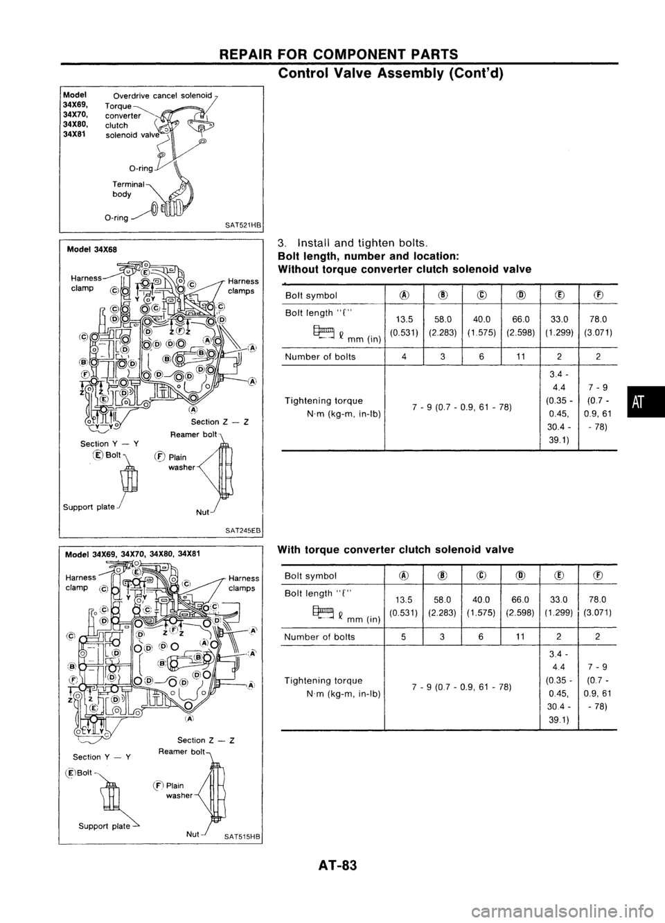
REPAIRFORCOMPONENT PARTS
Control ValveAssembly (Cont'd)
Model
34X69, 34X70,
34X80, 34X81 Overdrive
cancelsolenoid
Torque~ converter
clutch
'0
solenoid valv~
'"
o_rin~
Terminal
0
body
O-ring~
l\
SAT521HB
Section Z- Z
Reamer bolt
Model
34X68
•
Bolt
symbol
@
@
@
@
(!)
ffi
Bolt length "C"
13.558.0 40.0 66.0
33.078.0
~ Q
mm(in)
(0.531)
(2.283)(1.575) (2.598)(1.299)
(3.071)
Number ofbolts
4
3611
22
3.4 -
4.4 7-9
Tightening torque
7-9 (0.7 -0.9, 61-78) (0.35
-(0.7 -
N'm (kg-m, in-Ib)
0.45,
0.9,61
30.4 - -78)
39.1)
3.
Install andtighten bolts.
Bolt length, number andlocation:
Without torqueconverter clutchsolenoid valve
/
Nut
(:E)
Plain
washer
Section
y- y
@Bolt~
Support plate
r
SAT245EB
Section
y- y
Section
Z- Z
Reamer bolt With
torque converter clutchsolenoid valve
Bolt symbol
@
@
@
@
(!)
ffi
Bolt length "C"
13.558.0
40.0 66.033.0
78.0
~ Q
mm (in)
(0.531)
(2.283)
(1.575) (2.598)(1.299)
(3.071)
Number ofbolts
536
11 2
2
3.4 -
4.4 7-9
Tightening torque
7-9 (0.7 -0.9, 61-78) (0.35
-(0.7 -
N'm (kg-m, in-Ib)
0.45,
0.9,61
30.4 --
78)
39.1)
(ElBolt -
. S"PP~
en
Plain
washer
AT-83
Page 87 of 1701
REPAIRFORCOMPONENT PARTS
Control ValveUpper Body(Cont'd)
DISASSEMBL Y
1. Remove valvesatretainer plates.
• Donot use amagnetic "hand".
SAT114D
a.Use ascrewdriver toremove retainer plates.
SAT135D
b.Remove retainerplateswhileholding spring,plugsand•
sleeves.
• Remove plugslowly toprevent internalpartsfromjumping
out.
c. Place mating surface ofvalve facedown, andremove inter-
nal parts.
• If
avalve ishard toremove, placevalvebodyfacedown and
lightly tapitwith asoft hammer.
• Becareful nottodrop ordamage valvesandsleeves.
SAT137D INSPECTION
Q
(Length) Valve
spring
• Measure freelength andouter diameter ofeach valve
spring. Alsocheck fordamage ordeformation.
Inspection standard:
Refer to50S, AT-167.
• Replace valvesprings ifdeformed orfatigued.
Control valves
• Check sliding surfaces ofvalves, sleeves andplugs.
SAT138D
AT-87