Page 39 of 1701
REMOVALANDINSTALLATION
Removal
• Remove batteryandbracket.
• Remove airduct.
• Disconnect
AIT
solenoid harnessconnector, inhibitorswitch
harness connector andspeedometer pinionharness con-
nector.
• Disconnect throttlewireatengine side.
• Drain ATF.
• Remove undercover andside cover.
• Disconnect controlcablefromtransaxle.
• Disconnect oilcooler hoses.
• Remove driveshafts -Refer toFA section ("Removal", •
"FRONT AXLE-Drive Shaft").
• Remove exhaustfronttube.
• Remove startermotorfromtransaxle.
• Remove frontandrear gussets andengine rearplate.
• Remove boltssecuring torqueconverter todrive plate.
Rotate crankshaft foraccess tosecuring bolts.
• Support enginebyplacing ajack under oilpan.
Do not place jackunder oilpan drain plug.
• Support transaxle withajack.
• Remove LHand rear mountings fromtransaxle.
• Remove boltsfixing
AIT
toengine.
• Lower transaxle whilesupporting
it
with ajack.
AT-39
Page 162 of 1701
SAT070D
a-ring
SAT160EASSEMBLY
Assembly 4(Cont'd)
b. Install newoilpan gasket ontransmission case.
c. Install oilpan ontransmission case.
• Always replace oilpan bolts.
• Tighten thefour bolts inacriss-cross patterntoprevent
dislocation ofgasket.
d. Tighten drainplugtospecified torque.
13. Install governor valve.
a. Install governor valveassembly intotransmission case.
b. Install O-ring togovernor cap.
• Apply ATFtoa-ring.
c. Install governor caponto transmission case.
d. Install snapringonto transmission casewithascrewdriver.
• Align snapringgapwith thenotch oftransmission case.
AT-162
Page 163 of 1701
SAT620E
SAT586H
SAT428DA
Torque
converter
ASSEMBLY
Assembly 4(Cont'd)
14. Install inhibitor switch.
a. Set manual shaftin"P" position.
b. Temporarily installinhibitor switchonmanual shaft.
c.
Move
selector
lever
to"N" position.
d. Use a4mm (0.157 in)pin forthis adjustment.
1) Insert thepinstraight intothemanual shaftadjustment hole.
2) Rotate inhibitor switchuntilthepincan also beinserted
straight intohole ininhibitor switch.
e. Tighten inhibitor switchfixingbolts.
f. Remove pinfrom adjustment holeafter adjusting inhibitor
switch.
15. Install oilcharging pipeandoilcooler tubetotransmission •
case.
16. Install torque converter.
a. Pour ATFintotorque converter.
• Approximately 1liter (7/8Impqt)offluid isrequired fora
new torque converter.
• When reusing oldtorque converter, addthesame amount
of fluid aswas drained.
b. Install torque converter whilealigning notchesoftorque
converter withnotches ofoil pump.
AT-163
Page 278 of 1701

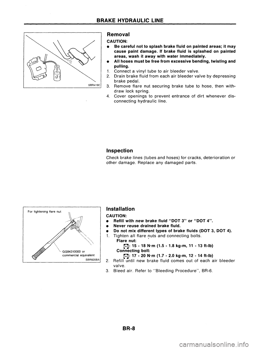
BRAKEHYDRAULIC LINE
SBR419C
For tightening flarenut
~GG94310000
or
commercial equivalent
SBR820BA
Removal
CAUTION: • Becareful nottosplash brakefluidonpainted areas;itmay
cause paintdamage. Ifbrake fluidissplashed onpainted
areas, washitaway withwater immediately.
• Allhoses mustbefree from excessive bending,tWistingand
pulling.
1 ~ Connect a
vinyl
tubetoair bleeder
valve~
2. Drain brake fluidfrom each airbleeder
valve
bydepressing
brake pedal.
3. Remove
flarenutsecuring braketubetohose, thenwith-
draw lockspring.
4. Cover
openings to
prevent
entrance ofdirt
whenever
dis-
connecting hydraulicline.
Inspection
Check brakelines(tubes andhoses) forcracks, deterioration or
other damage. Replaceanydamaged parts.
Installation
CAUTION:
• Refill withnewbrake fluid"DOT 3"or"DOT 4".
• Never reusedrained brakefluid.
• Donot mix different typesofbrake fluids(DOT3,DOT 4).
1. Tighten allflare nutsandconnecting bolts.
Flare nut: .
~: 15-18 N'm (1.5-1.8 kg-m, 11-13 ft-Ib)
Connecting bolt:
~: 17-20 N'm (1.7-2.0 kg-m, 12-14 ft-Ib)
2. Refill untilnewbrake fluidcomes outofeach airbleeder
valve.
3. Bleed air.Refer to"Bleeding Procedure", BR-6.
BR-8
Page 280 of 1701

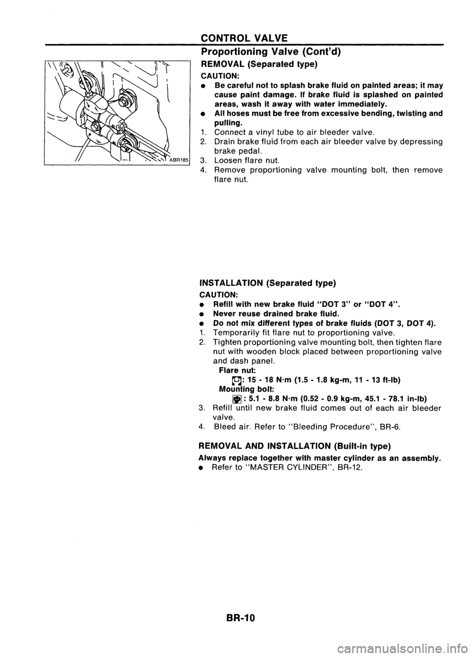
CONTROLVALVE
Proportioning Valve(Cont'd)
REMOVAL (Separated type)
CAUTION:
• Becareful nottosplash brakefluidonpainted areas;itmay
cause paintdamage. Ifbrake fluidissplashed onpainted
areas, washitaway withwater immediately.
• Allhoses mustbefree from excessive bending,twistingand
pulling.
1. Connect avinyl tubetoair bleeder valve.
2. Drain brake fluidfrom each airbleeder valvebydepressing
brake pedal.
3. Loosen flarenut.
4. Remove proportioning valvemounting bolt,then remove
flare nut.
INSTAllATION (Separatedtype)
CAUTION:
• Refill withnewbrake fluid"DOT 3"or"DOT 4".
• Never reusedrained brakefluid.
• Donot mix different typesofbrake fluids(DOT3,DOT 4).
1. Temporarily fitflare nuttoproportioning valve.
2. Tighten proportioning valvemounting bolt,then tighten flare
nut with wooden blockplaced between proportioning valve
and dash panel.
Flare nut:
tDJ:
15-18 N'm (1.5-1.8 kg-m, 11-13 ft-Ib)
Mounting bolt:
11]:
5.1-8.8 N'm (0.52 -0.9 kg-m, 45.1-78.1 in-Ib)
3. Refill untilnewbrake fluidcomes outofeach airbleeder
valve.
4. Bleed air.Refer to"Bleeding Procedure", BR-6.
REMOVAL ANDINSTAllATION (Built-intype)
Always replace together withmaster cylinder asan assembly.
• Refer to"MASTER CYLINDER", BR-12.
BR-10
Page 294 of 1701
FRONTDISCBRAKE
Installation
CAUTION:
• Refill withnewbrake fluid"DOT 3"or"DOT 4".
• Never reusedrained brakefluid.
• Donot mix different typesofbrake fluids(DOT3,DOT 4).
1. Install caliper assembly.
2. Install brakehosetocaliper securely.
3. Install allparts andsecure allbolts.
4. Bleed air.Refer to"Bleeding Procedure", BR-6.
BR-24
Page 305 of 1701
SBR646REAR
DISCBRAKE
Assembly (Cont'd)
8. Insert piston sealintogroove oncylinder body.
9. With piston bootfitted topiston, insertpiston bootinto
groove oncylinder bodyandfitpiston byturning itclock-
wise withlong nose pliers, orsuitable tool.
Commercial
service
1001
SBR868C
10.Fittoggle lever,return spring andcable guide.
Installation
CAUTION:
• Refill withnewbrake fluid"DOT 3"or"DOT
4".
• Never reusedrained brakefluid.
• Donot mix different typesofbrake fluids(DOT3,DOT
4).
1. Install caliper assembly.
2. Install brakehosetocaliper securely.
3. Install allparts andsecure allbolts.
4. Bleed air.Refer to"Bleeding Procedure", BR-6.
BR-35
•
Page 313 of 1701
ANTI-LOCKBRAKESYSTEM
Removal andInstallation (Cont'd)
1. Disconnect batterycable.
2. Drain brake fluid.Refer toSR-5.
3. Discharge airconditioner refrigerant.RefertoHA section
("R-134a ServiceProcedure", "SERVICEPROCEDURES").
4. Disconnect allconnectors fromASSrelay bracket.
5. Remove mounting boltforrelay bracket.
6. Remove ASSrelay boxwith bracket.
7. Remove airconditioner low-pressure tubes.RefertoHA
section, ("Refrigerant Lines","SERVICE PROCEDURES") .
8. Disconnect brakepipesandmove awayfromactuator.
It is not necessary toremove thesepipesfromvehicle.
9. Remove/loosen mountingnutsbetween actuatorand
bracket.
BR-43
•