Page 1093 of 1701
VE-TYPE INJECTION PUMP
SEF779A
Adjustment
INJECTION TIMINGADJUSTMENT (Plunger
lift
adjustment)
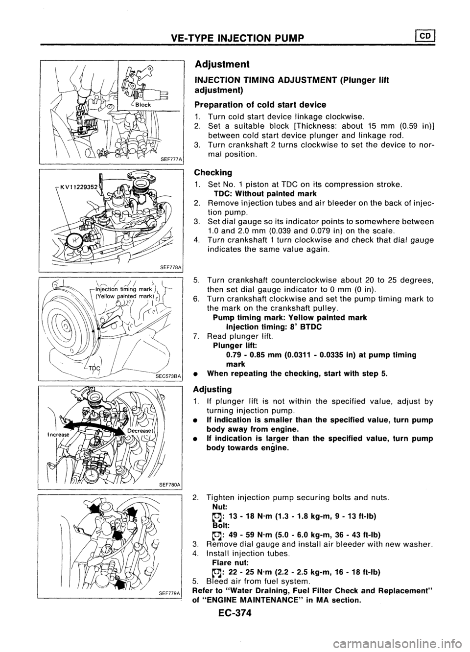
Preparation ofcold start device
1. Turn coldstart device linkage clockwise.
2. Set asuitable block[Thickness: about15mm (0.59 in)]
between coldstart device plunger andlinkage rod.
3. Turn crankshaft 2turns clockwise toset the device tonor-
mal position.
Checking
1. Set NO.1 piston atTDC onitscompression stroke.
TDC: Without paintedmark
2. Remove injection tubesandairbleeder onthe back ofinjec-
tion pump.
3. Set dial gauge soitsindicator pointstosomewhere between
1.0 and 2.0mm (0.039 and0.079 in)onthe scale.
4. Turn crankshaft 1turn clockwise andcheck thatdialgauge
indicates thesame value again.
5. Turn crankshaft counterclockwise about20to25 degrees,
then setdial gauge indicator to0mm (0in).
6. Turn crankshaft clockwiseandsetthe pump timing markto
the mark onthe crankshaft pulley.
Pump timing mark:Yellow painted mark
Injection timing:8
0
BTDC
7. Read plunger lift.
Plunger lift:
0.79 -0.85 mm(0.0311 -0.0335 in)atpump timing
mark
• When repeating thechecking, startwithstep 5.
Adjusting
1. Ifplunger liftisnot within thespecified value,adjust by
turning injection pump.
• Ifindication issmaller thanthespecified value,turnpump
body away fromengine.
• Ifindication islarger thanthespecified value,turnpump
body towards engine.
2. Tighten injection pumpsecuring boltsandnuts.
Nut:
~: 13-18 N.m (1.3-1.8 kg-m, 9-13 ft-Ib)
Bolt:
~: 49-59 N.m (5.0-6.0 kg-m, 36-43 ft-Ib)
3. Remove dialgauge andinstall airbleeder withnewwasher.
4. Install injection tubes.
Flare nut:
~: 22-25 N.m (2.2-2.5 kg-m, 16-18 ft-Ib)
5. Bleed airfrom fuelsystem.
Refer to"Water Draining, FuelFilter Check andReplacement"
of "ENGINE MAINTENANCE" inMA section.
EC-374
Page 1171 of 1701
ENGINECOOLING SYSTEM
Water Pump
REMOVAL ANDINSTALLATION
1. Drain engine coolant fromradiator andcylinder block.
2. Remove upperradiator hose,timing beltcovers, front
engine mounting bracketandtiming belt.
3. Remove timingbelttensioner andidler andtiming belt
lower backcover.
~
Drain plug(Radiator)
4.Remove waterpump.
• For installation, applyliquidgasket towater pumpasshown
in the figure.
2.5:!:0.5
Bolt hRille (0.098:!:0.020r12.5:!: 0.5
die. (0.098:!:0.020)
dIe.
Unit: mm(in) SLC565A
*:
Apply liquidsealant tothe thread.
~/ ~~;>
~/ ~l!.
to.J
M7: 16-20 N.m (1.6-2.0 kg-m, 12-14 ft-Ib)
M8: 16-21 N.m (1.6-2.1 kg-m, 12-15 ft-Ib)
SLC563A
LC-33
•
Page 1199 of 1701
TIMINGCHAIN
Without
VTC
CAUTION:
• After removing timingchain,donot turn crankshaft and
camshaft separately, orvalves willstrike piston heads.
• When installing camshafts, chaintensioner, oilseals, or
other sliding parts,lubricate contacting surfaceswithnew
engine oil.
• Apply newengine oiltobolt threads andseat surfaces when
installing cylinderhead,camshaft sprocket,crankshaft
pulley, andcamshaft brackets.
Removal
1. Drain engine coolant fromradiator andcylinder block.
Be careful nottospill coolant ondrive belts.
2. Release fuelpressure. '
Refer to"Releasing FuelPressure" inEG section.
3.. Remove thefollowing belts.
• Power steering pumpdrivebelt
• Alternator drivebelt
4. Remove powersteering pulleyandpump withbracket.
5. Remove airduct tointake manifold collector.
6. Remove frontright-side wheel.
7. Remove frontright-side splashcover.
8. Remove frontundercovers.
9. Remove frontexhaust tube.
10. Remove cylinderheadfrontmounting bracket.
11. Remove rockercover.
12. Remove distributor cap.
13. Remove allspark plugs.
14. Remove intakemanifold support.
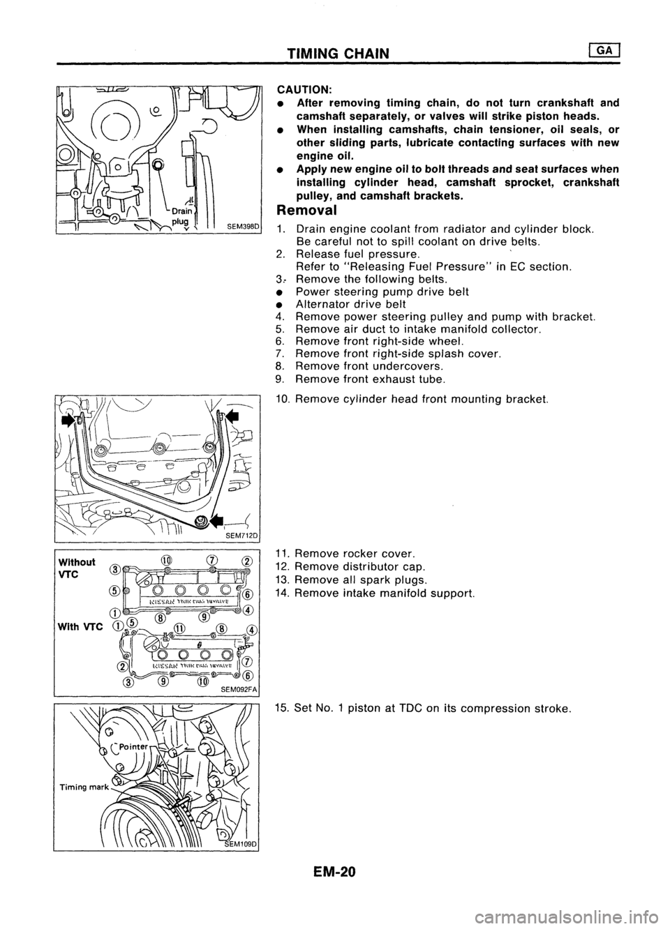
15. Set NO.1 piston at
TOG
onitscompression stroke.
EM-20
Page 1224 of 1701
ENGINEREMOVAL
WARNING:
a. Situate vehicle onaflat and solid surface.
b. Place chocks atfront andback ofrear wheels.
c. Donot remove engineuntilexhaust systemhascompletely
cooled off.
Otherwise, youmay burn yourself and/orfiremay break out
in fuel line.
d. For safety during subsequent steps,thetension ofwires
should beslackened againsttheengine.
e. Before disconnecting fuelhose, release fuelpressure from
fuel line.
Refer to"Releasing FuelPressure" inEC section.
f. Besure tohoist engine andtransaxle inasafe manner.
g. For engines notequipped withengine slingers, attach
proper slingers andbolts described inPARTS CATALOG.
CAUTION:
• When liftingengine, besure toclear surrounding parts.
Take special careforaccelerator wirecasing, brakelines
and brake master cylinder.
• Inhoisting theengine, alwaysuseengine slingers inasafe
manner.
• Inremoving driveshaft, becareful nottodamage grease
seal oftransaxle.
Engine cannotberemoved separately fromtransaxle. Remove
engine withtransaxle.
Removal
1. Drain water.
2. Remove hood.
3. Remove battery.
4. Remove reservoir tankandbracket.
5. Remove drivebelts.
6. Remove alternator, compressor andpower steering oil
pump fromengine.
Power steering pumpdoesnotneed tobe disconnected from
power steering tubes.
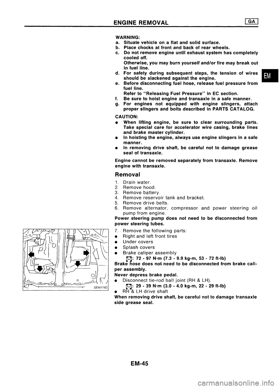
7. Remove thefollowing parts:
• Right andleftfront tires
• Under covers
• Splash covers
• Brake caliper assembly
~: 72-97 N'm (7.3•9.9 kg-m, 53•72 ft-Ib)
Brake hosedoes notneed tobe disconnected frombrake cali-
per assembly.
Never depress brakepedal.
• Disconnect tie-rodballjoint (RH
&
LH).
~: 29-39 N'm (3.0-4.0 kg-m, 22-29 ft-Ib)
• RH
&
LH drive shaft
When removing driveshaft, becareful nottodamage transaxle
side grease seal.
EM-45
•
Page 1227 of 1701
CYLINDERBLOCK
CAUTION:
• When installing slidingparts(bearings, pistons,etc.),lubri-
cate contacting surfaceswithnewengine oil.
• Place removed partssuchasbearings andbearing capsin
their proper orderanddirection.
• When installing connecting rodnuts, andmain bearing cap
bolts, apply newengine oiltothreads andseating surfaces.
Disassembly
PISTON ANDCRANKSHAFT
1. Place engine onawork stand.
2. Drain coolant andoil.
3. Remove timingchain.
Refer to"Removal" in"TIMING CHAIN"(EM-20).
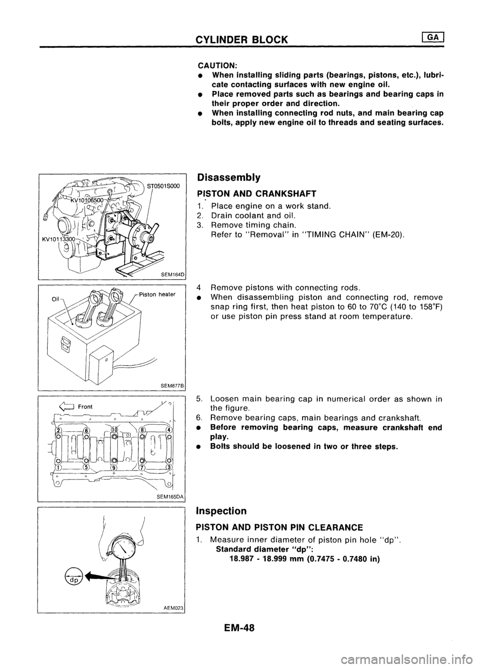
4 Remove pistonswithconnecting rods.
• When disassembling pistonandconnecting rod,remove
snap ringfirst, thenheat piston to60 to70°C (140to158°F)
or use piston pinpress stand atroom temperature.
5. Loosen mainbearing capinnumerical orderasshown in
the figure.
6. Remove bearingcaps,mainbearings andcrankshaft.
• Before removing bearingcaps,measure crankshaft end
play.
• Bolts should beloosened intwo orthree steps.
AEM023 Inspection
PISTON ANDPISTON PINCLEARANCE
1. Measure innerdiameter ofpiston pinhole "dp".
Standard diameter
"dp":
18.987 -18.999
mm
(0.7475 -0.7480
in)
EM-48
Page 1242 of 1701
OILPAN
SEC. 110
~ReIer to
"Installation".
@ @
~o o~
@ojooEE~CD
~]DOCn[l[ ~
~ @o
JCJC)Ol~CI /
i
CID
~:~~ne ~~
l[lCJL
L~
@ ~ ~'llrrlriQ)
@
=0
Q]J
5
Loosen innumerical order. SEM040D 6
Removal
1. Remove engineundercover.
2. Drain engine oil.
3. Remove steeloilpan bolts.
~
I ~
1.9-2.5
(0.19 -0.25,
16.5 -21.7)
CD
Side gallery baffleplate
W
Aluminum
011
pan
@
Rear cover plate
@l
DraIn plug
@ Steel
011
pan
SEM142FA
•
SEM602E
4.
Remove steeloilpan.
a. Insert Toolbetween aluminum oilpan and steel oilpan.
• Becareful nottodamage aluminum matingsurface.
• Do not insert screwdriver, oroil pan flange willbe
deformed.
EM-53
Page 1248 of 1701
TIMINGCHAIN
CAUTION:
• After removing timingchain,donot turn crankshaft and
camshaft separately, orvalves willstrike piston heads.
• When installing rockerarms,camshafts, chaintensioner, oil
seals, orother sliding parts,lubricate contacting surfaces
with newengine oil.
• Apply newengine oiltobolt threads andseat surfaces when•
installing cylinderhead,camshaft sprockets, crankshaft
pulley, andcamshaft brackets.
Removal
1. Release fuelpressure.
Refer to"Releasing FuelPressure" inEC section.
2. Remove engineundercovers.
3. Remove frontRHwheel andengine sidecover.
4. Drain coolant byremoving cylinderblockdrainplugand
radiator draincock.
5. Remove radiator.
6. Remove airduct tointake manifold.
7. Remove drivebeltsandwater pumppulley.
8. Remove alternator andpower steering oilpump.
9. Remove vacuumhoses,fuelhoses, wires,harness, connec-
tors andsoon.
10. Remove allspark plugs.
11. Remove rockercoverandoilseparator.
12. Remove intakemanifold supports.
EM-69
Page 1278 of 1701
SEM092DENGINE
REMOVAL
WARNING:
• Situate vehicle onaflat and solid surface.
• Place chocks atfront andback ofrear wheels.
• Donot remove engineuntilexhaust systemhascompletely
cooled off.
Otherwise, youmay burn yourself and/orfiremay break out
in fuel line.
• For safety during subsequent steps,thetension ofwires
should beslackened againsttheengine.
• Before disconnecting fuelhose, release fuelpressure from
fuel line.
Refer to"Releasing FuelPressure" inEC section.
• Besure tohoist engine andtransaxle inasafe manner.
• For engines notequipped withengine slingers, attach
proper slingers andbolts described inPARTS CATALOG.
CAUTION:
• When liftingengine, becareful nottostrike adjacent parts,
especially thefollowing: Accelerator wirecasing, brake
lines, andbrake master cylinder.
• Inhoisting theengine, alwaysuseengine slingers inasafe
manner.
Removal
1. Remove engineundercoverandhood.
2. Drain coolant frombothcylinder block,andradiator.
3. Drain engine oilfrom drain plugofoil pan.
4. Remove vacuumhoses,fuelhoses, wires,harness andcon-
nectors andsoon.
5. Remove exhausttubes,balljoints anddrive shafts.
6. Remove radiatorandfans.
7. Remove drivebelts.
8. Remove alternator, compressor andpower steering oil
pump fromengine.
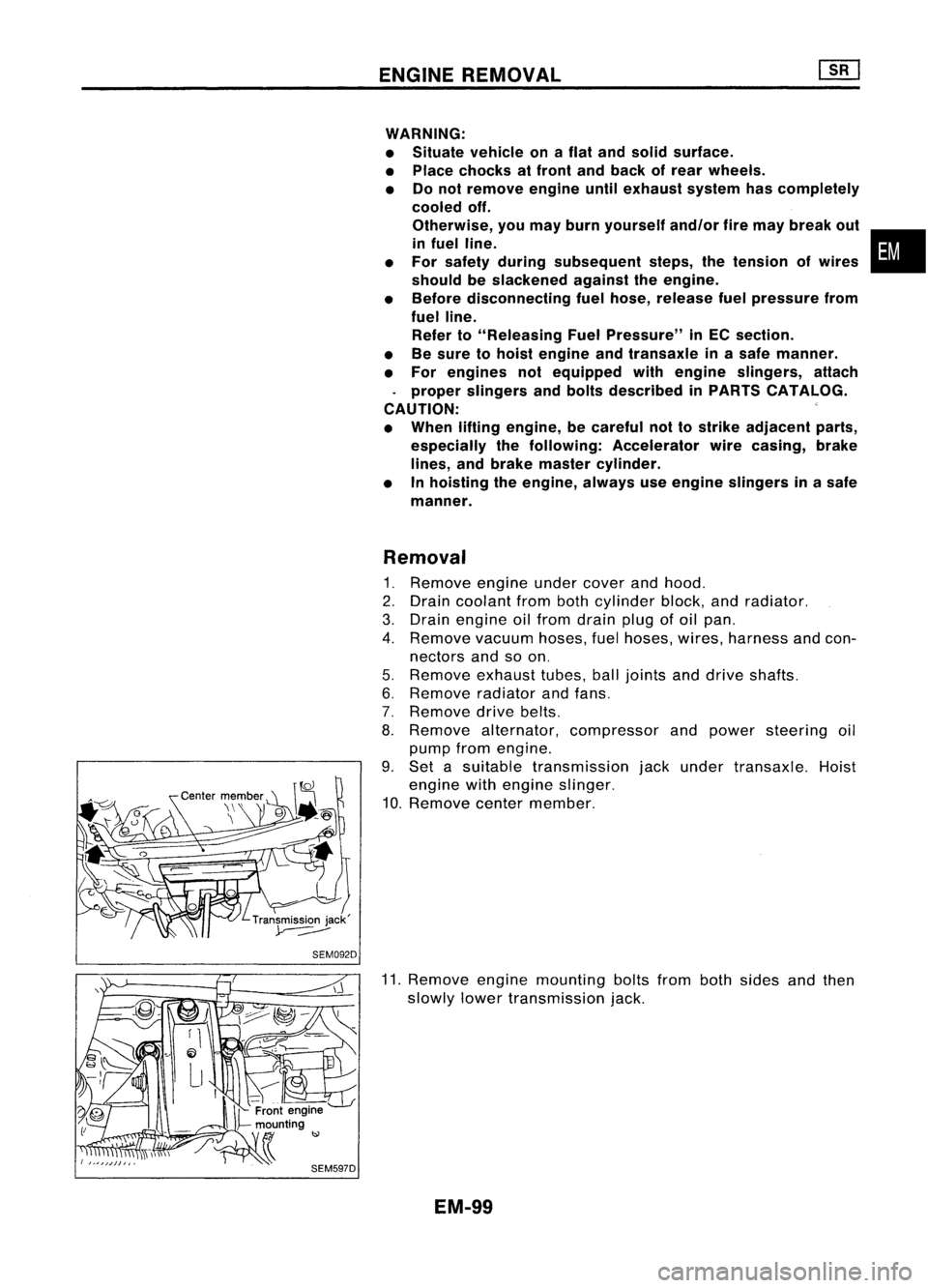
9. Set asuitable transmission jackunder transaxle. Hoist
engine withengine slinger.
10. Remove centermember.
11. Remove enginemounting boltsfrombothsides andthen
slowly lowertransmission jack.
EM-99
•