1995 NISSAN ALMERA N15 Head lamp
[x] Cancel search: Head lampPage 194 of 1701
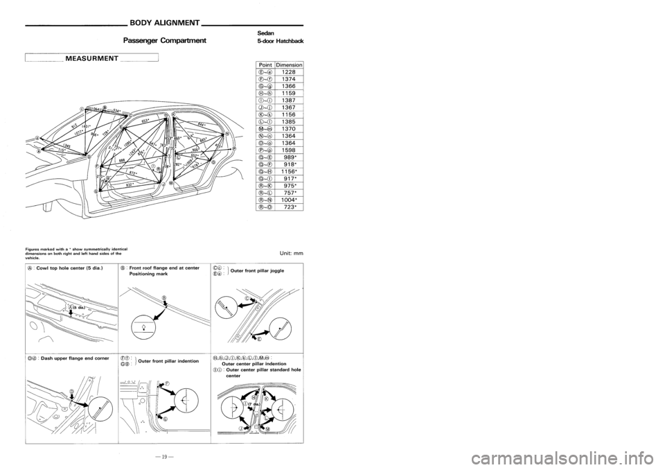
__________ BODYALIGNMENT _
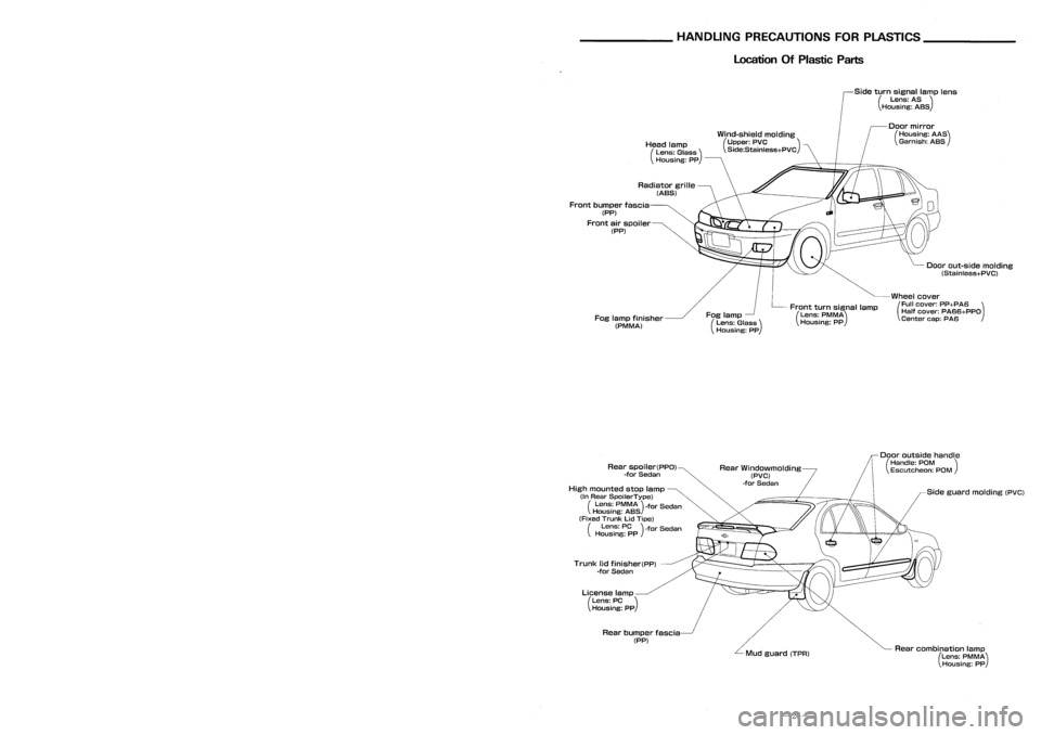
_HANDLINGPRECAUTIONS FORPLASTICS _
Passenger Compartment Sedan
5-door Hatchback Location
OfPlastic Parts
Side turnsignal lamplens
(Lens: AS)
Housing: ASS
Wind-shield molding
(Upper: PVC )
Side:Stainless+PVC
Doorout-side molding
(Stainless+PVC)
Wheel cover
(Full cover: PP+PA6 )
Half cover: PA66+PPO
Center cap:PA6
Door
mirror
(Housing: AAS)
Garnish: ASS
Front turnsignal lamp
(Lens: PMMA)
Housing: PP
Fog
lamp
(Lens: Glass)
Housing: PP
Head
lamp
(Lens: Glass)
Housing: pp
Radiator grille
(ABS)
Fog lamp finisher
(PM MA)
Front
bumper fascia
(PP)
Front airspoiler
(PP)
Point
Dimension
@-@
1228
CB-
@-@
1366
(8)-{6)
1159
CD--cD
1387
Q)-{J) 1367
@--@
1156
(b)--{[)
1385
~-4iV
1370
@~
1364
@~
1364
C'e)--@
1598
@--@
989*
@-{E)
918*
@~
1156*
@--{[)
917*
@~@
975*
@~(b)
757*
@~
1004*
@--@
723*
,
... ._MEASURMENT _
Figures marked witha
*
show symmetrically identical
dimensions onboth right andlefthand sides ofthe
vehicle.
Unit:
mm
@ :
Cowl tophole center (5dia.)
CB>
:
Front roofflange endatcenter
Positioning mark ~~
~}Outer frontpillarjoggle
Sideguard molding (PVC)
Rear combination lamp
(Lens: PMMA)
Housing: PP
Door
outside handle
(Handle: POM )
Escutcheon: POM
Mud guard (TPR)
Rear
Windowmolding
(PVC)
-for Sedan
Rear bumper fascia
(PP)
License
lamp
(Lens: PC)
Housing: PP
Trunk
lidfinisher(pp)
-for Sedan
Rear
spoiler(PPO)
-for Sedan
High mounted stoplamp
(In Rear SpoilerType)
(Lens: PMMA)-for Sedan
Housing: ASS
(Fixed Trunk LidTipe)
(Lens: PC)-for Sedan
Housing: PP
(f3),Cfi),Q),CD,@,@,CD,CD,~,@ :
Outer center pillarindention
CDCD :
Outer center pillarstandard hole
center
CBCD:
}
~@:
Outerfrontpillar indention
@@
:
Dash upper flange endcorner
-19- -26-
Page 201 of 1701
__________ BODYALIGNMENT _
_HANDLINGPRECAUTIONS FORPLASTICS _
Passenger Compartment Sedan
5-door Hatchback Location
OfPlastic Parts
Side turnsignal lamplens
(Lens: AS)
Housing: ASS
Wind-shield molding
(Upper: PVC )
Side:Stainless+PVC
Doorout-side molding
(Stainless+PVC)
Wheel cover
(Full cover: PP+PA6 )
Half cover: PA66+PPO
Center cap:PA6
Door
mirror
(Housing: AAS)
Garnish: ASS
Front turnsignal lamp
(Lens: PMMA)
Housing: PP
Fog
lamp
(Lens: Glass)
Housing: PP
Head
lamp
(Lens: Glass)
Housing: pp
Radiator grille
(ABS)
Fog lamp finisher
(PM MA)
Front
bumper fascia
(PP)
Front airspoiler
(PP)
Point
Dimension
@-@
1228
CB-
@-@
1366
(8)-{6)
1159
CD--cD
1387
Q)-{J) 1367
@--@
1156
(b)--{[)
1385
~-4iV
1370
@~
1364
@~
1364
C'e)--@
1598
@--@
989*
@-{E)
918*
@~
1156*
@--{[)
917*
@~@
975*
@~(b)
757*
@~
1004*
@--@
723*
,
... ._MEASURMENT _
Figures marked witha
*
show symmetrically identical
dimensions onboth right andlefthand sides ofthe
vehicle.
Unit:
mm
@ :
Cowl tophole center (5dia.)
CB>
:
Front roofflange endatcenter
Positioning mark ~~
~}Outer frontpillarjoggle
Sideguard molding (PVC)
Rear combination lamp
(Lens: PMMA)
Housing: PP
Door
outside handle
(Handle: POM )
Escutcheon: POM
Mud guard (TPR)
Rear
Windowmolding
(PVC)
-for Sedan
Rear bumper fascia
(PP)
License
lamp
(Lens: PC)
Housing: PP
Trunk
lidfinisher(pp)
-for Sedan
Rear
spoiler(PPO)
-for Sedan
High mounted stoplamp
(In Rear SpoilerType)
(Lens: PMMA)-for Sedan
Housing: ASS
(Fixed Trunk LidTipe)
(Lens: PC)-for Sedan
Housing: PP
(f3),Cfi),Q),CD,@,@,CD,CD,~,@ :
Outer center pillarindention
CDCD :
Outer center pillarstandard hole
center
CBCD:
}
~@:
Outerfrontpillar indention
@@
:
Dash upper flange endcorner
-19- -26-
Page 244 of 1701
INTERIORTRIM
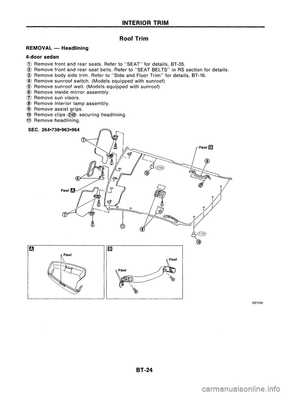
Roof Trim
REMOVAL -Headlining
4-door sedan
CD
Remove frontandrear seats. Referto"SEAT" fordetails, BT-35.
@
Remove frontandrear seat belts. Referto"SEAT BELTS" inRS section fordetails.
@)
Remove bodysidetrim. Refer to"Side andFloor Trim" fordetails, BT-16.
@
Remove sunroofswitch.(Models equipped withsunroof)
@
Remove sunroofwelt.(Models equipped withsunroof)
@
Remove insidemirror assembly.
([) Remove sunvisors.
@
Remove interiorlampassembly.
@
Remove assistgrips.
@)
Remove clips
@
securing headlining.
@
Remove headlining.
SEC. 264-738-963-964
9
Pawl'
Pawl SBT056
BT-24
Page 245 of 1701
INTERIORTRIM
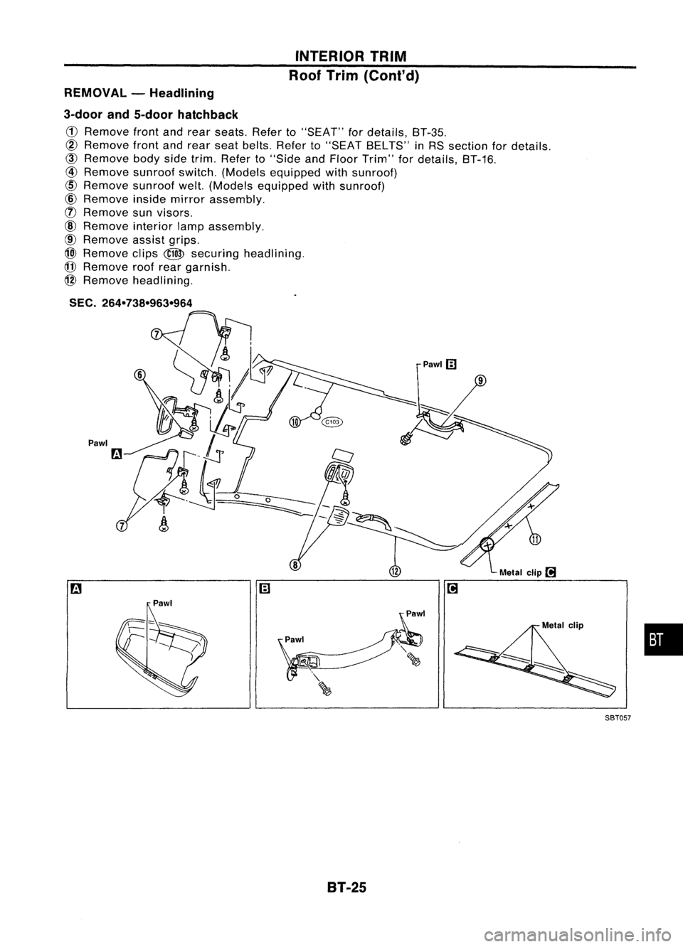
Roof Trim (Cont'd)
REMOVAL -Headlining
3-door and5-door hatchback
CD
Remove frontandrear seats. Referto"SEAT" fordetails, BT-35.
@
Remove frontandrear seat belts. Referto"SEAT BELTS" inRS section fordetails.
@)
Remove bodysidetrim. Refer to"Side andFloor Trim" fordetails, BT-16.
@
Remove sunroofswitch.(Models equipped withsunroof)
cID
Remove sunroofwelt.(Models equipped withsunroof)
@
Remove insidemirror assembly.
(f)
Remove sunvisors.
@
Remove interiorlampassembly.
@
Remove assistgrips.
@)
Remove clips
@
securing headlining.
(j]
Remove roofrear garnish.
@
Remove headlining.
SEC.
264-738-963-964
Pawl
•
Metal
clip
l!1
Pawlm
m
SBT05?
8T-25
Page 352 of 1701
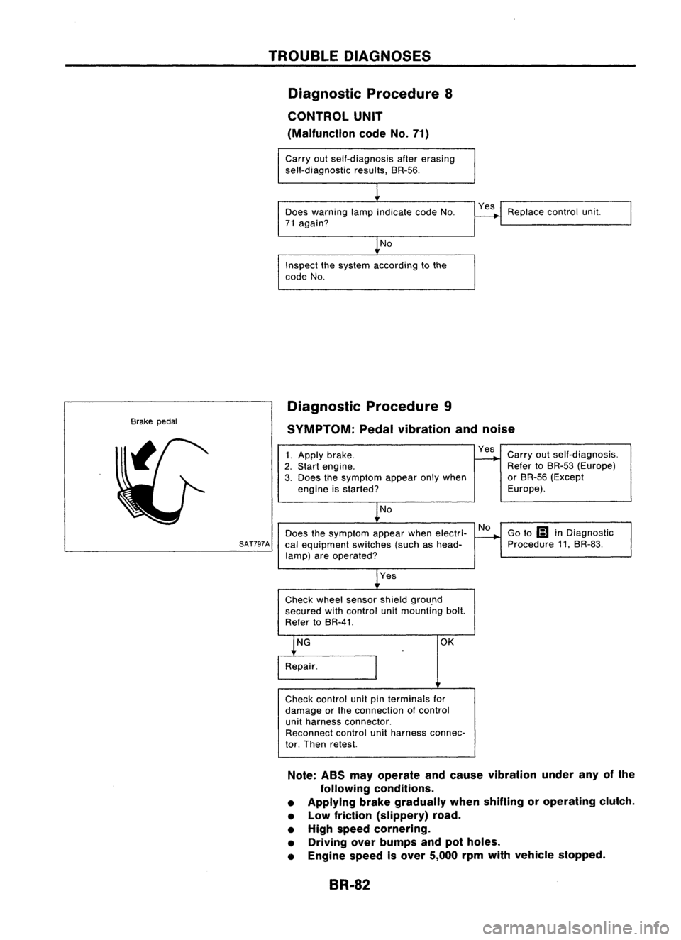
TROUBLEDIAGNOSES
Diagnostic Procedure8
CONTROL UNIT
(Malfunction codeNo.71)
Carry outself-diagnosis aftererasing
self-diagnostic results,BR-56.
Does warning lampindicate codeNo.
71 again?
No
Inspect thesystem according tothe
code No. Yes
Replace controlunit.
Brake pedal Diagnostic
Procedure9
SYMPTOM: Pedalvibration andnoise
No
Does thesymptom appearwhenelectri-
SAT797A
calequipment switches(suchashead-
lamp) areoperated?
1.
Apply brake.
2. Start engine.
3. Does thesymptom appearonlywhen
engine isstarted?
No
Yes
Check wheelsensor shieldgrou.nd
secured withcontrol unitmounting bolt.
Refer toBR-41. Yes
Carryoutself-diagnosis.
Refer toBR-53 (Europe)
or BR-56 (Except
Europe).
Go to
Ii1
inDiagnostic
Procedure 11,BR-83.
OK
Check control unitpinterminals for
damage orthe connection ofcontrol
unit harness connector.
Reconnect controlunitharness connec-
tor. Then retest.
Note: ABSmayoperate andcause vibration underanyofthe
following conditions.
• Applying brakegradually whenshifting oroperating clutch.
• Low friction (slippery) road.
• High speed cornering.
• Driving overbumps andpotholes.
• Engine speedisover 5,000 rpmwith vehicle stopped.
BR-82
Page 373 of 1701

ELECTRICALSYSTEM
SECTION
EL
When youread wiring diagrams:
• Read GIsection, "HOWTOREAD WIRING DIAGRAMS".
When youperform troublediagnos.es, readGIsection, "HOWTOFOllOW FLOWCHART
IN TROUBLE DIAGNOSES" and"HOW TOPERFORM EFFICIENT DIAGNOSIS FORAN
ELECTRICAL INCIDENT".
CONTENTS
PRECAUTIONS 4
Supplemental RestraintSystem(SRS)"AIR
BAG" (DualAirBag System) 4
Supplemental RestraintSystem(SRS)"AIR
BAG" (Single AirBag System) 4
HARNESS CONNECTOR 5
Description 5
STANDARDIZED RELAy 6
Description 6
POWER SUPPLY ROUTING 8
Schematic 8
Wiring Diagram -POWER - 10
Fuse 19
Fusible Link 19
Circuit Breaker 19
GROUND DISTRIBUTION 20
BATTERy 25
How toHandle Battery 25
Battery TestandCharging Chart.. 28
Service DataandSpecifications (SOS) 32
STARTING SySTEM
33
Wiring Diagram -START - 33
Trouble Diagnoses 35
Construction 36
Removal andInstallation .45
Magnetic SwitchCheck .46
Pinion/Clutch Check 46
Brush Check 46
Yoke Check 47
Armature Check 48
Assembly .49
Service DataandSpecifications (SDS) 50
CHARGING SYSTEM 52
Wiring Diagram -CHARGE - 52
Trouble Diagnoses 54Construction
55
Removal andInstallation 57
Disassembly 57
Rotor Check 57
Brush Check 58
Stator Check 58
Diode Check 59
Assembly 60
Service DataandSpecifications (SDS) 61
COMBINATION SWITCH 62
Combination Switch/Check 62
Replacement 64
HEADLAMP -Without Daytime lightSystem -65
Wiring Diagram -H/LAMP - 65
Trouble Diagnoses 67
HEADLAMP -Daytime lightSystem - 68
Operation (Daytimelightsystem) 68
System Description 69
Schematic 70
Wiring Diagram -DTRL - 71
Trouble Diagnoses (DaytimeLight) 74
HEADLAMP 75
Bulb Replacement... 75•
Aiming Adjustment. 75
HEADLAMP -Headlamp Aiming
Control- 77
Wiring Diagram -AIM - 77
Description 81
EXTERIOR LAMP 82
Clearance, LicenseandTail Lamps/Schematic 82
Clearance, LicenseandTail Lamps/Wiring
Diagram -TAILIL - 83
Stop Lamp/Wiring Diagram-STOP/L - 92
Back-up Lamp/Wiring Diagram-BACK/L -94
Front FogLamp/Wiring Diagram-F/FOG -96
Front FogLamp BulbReplacement 101
Page 374 of 1701

CONTENTS(Conl'd.)
Front FogLamp Aiming Adjustment.. 101
Rear FogLamp/Wiring Diagram-R/FOG -102
Turn Signal andHazard Warning Lamps/
Schematic 106
Turn Signal andHazard Warning
Lamps/Wiring Diagram-TURN - 107
Turn Signal andHazard Warning
Lamps/Trouble Diagnoses 113
Combination FlasherUnitCheck 113
Bulb Specifications 114
INTERIOR LAMP 115
Illumination/Schematic 115
Illumination/Wiring Diagram-ILL - 116
Interior, Spot,Trunk Room andLuggage
Room Lamps/Wiring Diagram-INT/L - 122
Bulb Specifications 126
METER ANDGAUGES 127
Combination Meter 127
Speedometer, Tachometer,Temp.andFuel
Gauges/Wiring Diagram-METER - 129
Inspection/Fuel GaugeandWater
Temperature Gauge 133
Inspection/Tachometer 134
Inspection/Speedometer andVehicle Speed
Sensor 135
Fuel Tank Gauge UnitCheck 137
Thermal Transmitter Check 137
Vehicle SpeedSensor SignalCheck 137
WARNING LAMPSANDBUZZER 138
Warning Lamps/Schematic 138
Warning Lamps/Wiring Diagram-WARN -139
Oil Pressure SwitchCheck 151
Fuel Warning LampSensor Check 151
Diode Check 151
Warning BuzzerUnit... 151
Warning Buzzer/System Description 152
Warning Buzzer/Wiring Diagram
- BUZZER - 154
Components Inspection-Warning Buzzer 157
WIPER ANDWASHER 160
Front Wiper andWasher/System Description160
Front Wiper andWasher/Wiring Diagram
- WIPER - 162
Front Wiper Amplifier Check 166
Front Wiper Installation andAdjustment.. 166
Front Wiper Linkage 167
Front Washer NozzleAdjustment... 168
Front Washer TubeLayout 168
Rear Wiper andWasher/System Description169Rear
Wiper andWasher/Wiring Diagram
- WIP/R - 171
Rear Wiper Amplifier Check 175
Rear Wiper Installation andAdjustment.. 175
Rear Washer NozzleAdjustment 175
Rear Washer TubeLayout.. 176
Check Valve(forrear washer) 176
Headlamp WiperandWasher/Wiring Diagram
- HLC - 177
Headlamp WiperMotorCheck 179
Headlamp WiperInstallation 179
Headlamp WasherTubeLayout.. 179
Check Valve(Forheadlamp washer) 179
POWER WINDOW 180
System Description 180
Schematic 183
Wiring Diagram -WINDOW - 185
Trouble Diagnoses 197
POWER DOORLOCK 198
System Description 198
Schematic 200
Wiring Diagram -D/LOCK - 202
Trouble Diagnoses -Type 1(For Europe and
Austral ia) 212
Trouble Diagnoses -Type 2(Except for
Europe andAustralia) 216
POWER DOORMIRROR 220
Wiring Diagram -MIRROR - 220
ELECTRIC SUNROOF 224
Wiring Diagram -SROOF - 224
HORN, CIGARETTE LIGHTERANDCLOCK 226
Wiring Diagram -HORN - 226
REAR WINDOW DEFOGGER ANDDOOR
MIRROR DEFOGGER 230
System Description (Formodels withdaytime
light system) 230
Wirin.g Diagram -DEF - 231
Filament Check 235
Fi lament Repai
r
236
AUDIO ANDANTENNA 237
Audio/System Description 237
Wiring Diagram -AUDIO - 238
Radio FuseCheck 243
Location ofAntenna 243
Antenna RodReplacement.. 243
HEATED SEAT 245
Wiring Diagram -H/SEAT - 245
NATS (Nissan Anti-Theft System) 247
System Description 247
System Composition 247
Page 392 of 1701

GROUNDDISTRIBUTION
GROUND CONNECTTO CONN.
NO. CELLCORD
E37/E51 AIRBAG DIAGNOSIS SENSORUNIT(Single
E108 RS-SRS
air bag system)
BRAKE FLUIDLEVEL SWITCH E2EL-WARN
CLEARANCE LAMPLH E50EL-TAILIL
CLEARANCE LAMPRH E33EL-TAILIL
COOLING FANMOTOR-1 (1-modetype) E45 EC-COOLIFHA-A/C
COOLING FANMOTOR-1 (2-modetype-GA
E66 EC-COOLIF
HA-A/C
engine forEurope)
COOLING FANMOTOR-1 (2-modetype-ex-
E46 EC-COOLIF
HA-A/C
eept GAengine forEurope)
COOLING FANMOTOR-2 (1-modetype)
E39 EC-COOLIFHA-A/C
-
COOLING FANMOTOR-2 (2-modetype-GA
E67 EC-COOLiF
HA-A/C
engine forEurope)
COOLING FANMOTOR-2 (2-modetype-ex-
E40 EC-COOLIFHA-A/C
eept GAengine forEurope)
COOLING FANRELAY-1 E12
EC-COOLIFHA-A/C
COOLING FANRELAY-2 E17
EC-COOLIFHA-A/C
COOLING FANRELAY-3 E18EC-COOLIF
HA-A/C
DAYTIME LIGHTUNIT E119EL-DTRL
FRONT FOGLAMP LH E52EL-F/FOG
FRONT FOGLAMP RH
E36EL-F/FOG
FRONT TURNSIGNAL LAMPLH E53EC-TURN
FRONT TURNSIGNAL LAMPRH E32EC-TURN
FRONT WIPERANDWASHER SWITCH E113
EL-WIPER
FUEL FILTER SWITCH
E5EL-WARN
HEADLAMP AIMINGMOTOR UNITLH E48
EL-AIM
HEADLAMP AIMINGMOTOR UNITRH E35 EL-AIM
HEADLAMP LH E49EL-H/LAMP
EL-DTRL
HEADLAMP RH E34EL-H/LAMP
EL-DTRL
HEADLAMP WIPERMOTOR LH E44
EL-HLC
HEADLAMP WIPERMOTOR RH E41EL-HLC
IACV-FICD SOLENOID VALVE(LHDmodels
.
E65 EC-A/CCUTHA-A/C
with CD20 engine)
INHIBITOR SWITCH E222EC-PNP/SWAT-A
IT EL-START
NEUTRAL POSITION SWITCH E220EC-PNP/SW
POWER STEERING OILPRESSURE SWITCH
E3 EC-PST/SW
(RHO models withgasoline engine)
REAR FOGLAMP RELAY E20EL-R/FOG
REAR WIPER ANDWASHER SWITCH E112EL-WIP/R
REAR WIPER RELAY E15EL-WIP/R
SIDE TURN SIGNAL LAMP(Driver side) E1 EL-TURN
WASHER FLUIDLEVEL SWITCH E30EL-WARN
EL-20