Page 452 of 1701
HEADLAMP-Headlamp AimingControl -
Wiring Diagram -AIM -(Cont'd)
EL-AIM-04
G
J
FUSE]
BLOCK
(JIB)
Referto
----- ~EL-POWER.
I
a.
3 -,
----I
N.B
I
(Et06)
R/L
RIG
I
Refer
to
EL-POWER.
LIGHTING SWITCH
.....
<€l-
WIG
.....
Preceding
<&
B/R
.....
page
<@-
B/L
.....
<@-
RIW
U:i=U
ll:iJl ~
IbjJJ
WIG
B/R B/LRIW HEADLAMP
AIMING
SWITCH
(8TI)
~ B
I
B
rn~
IJOINT
CONNECTOR-4
~
L4=JJ
B
I
T-,
n
B BBB
1
!..1
1
(M2B)
m:m:I:illIillTI ~
~P
EL-80
Refer
tolast page
(Foldout page).
HEL022
Page 453 of 1701

HEADLAMP-Headlamp AimingControl -
Reversing
relay
Thermistor
Reversing
relay
Thermistor
Reversing
relay
::- Thermistor
+
BATIERY
A o
1
2
3
SEL465M
+
BATIERY
o
1
2
3
SEL364P
+
BATIERY
o
1
2
3
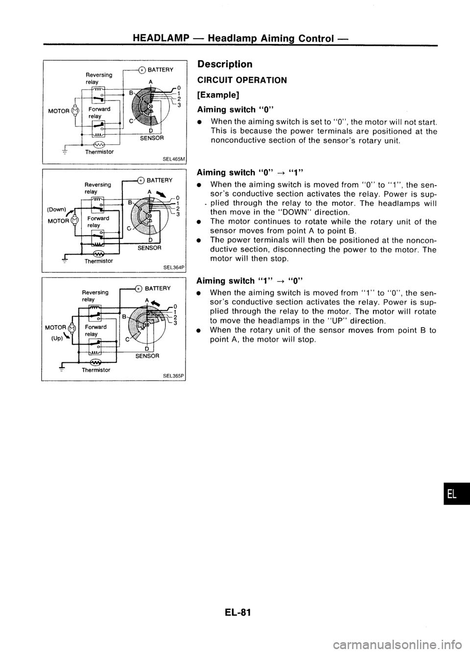
SEL365P Description
CIRCUIT OPERATION
[Example]
Aiming switch
"0"
• When theaiming switchisset to"0", themotor willnotstart.
This isbecause thepower terminals arepositioned atthe
nonconductive sectionofthe sensor's rotaryunit.
Aiming switch
"0"
-t
"1"
• When theaiming switchismoved from"0"to"1", thesen-
sor's conductive sectionactivates therelay. Power issup-
. plied through therelay tothe motor. Theheadlamps will
then move inthe "DOWN" direction.
• The motor continues torotate whiletherotary unitofthe
sensor movesfrompoint Ato point B.
• The power terminals willthen bepositioned atthe noncon-
ductive section, disconnecting thepower tothe motor. The
motor willthen stop.
Aiming switch"1"
-t
"0"
• When theaiming switchismoved from"1"to"0", thesen-
sor's conductive sectionactivates therelay. Power issup-
plied through therelay tothe motor. Themotor willrotate
to move theheadlamps inthe "UP" direction.
• When therotary unitofthe sensor movesfrompoint Bto
point A,the motor willstop.
EL-81
•
Page 473 of 1701

GEL001EXTERIOR
LAMP
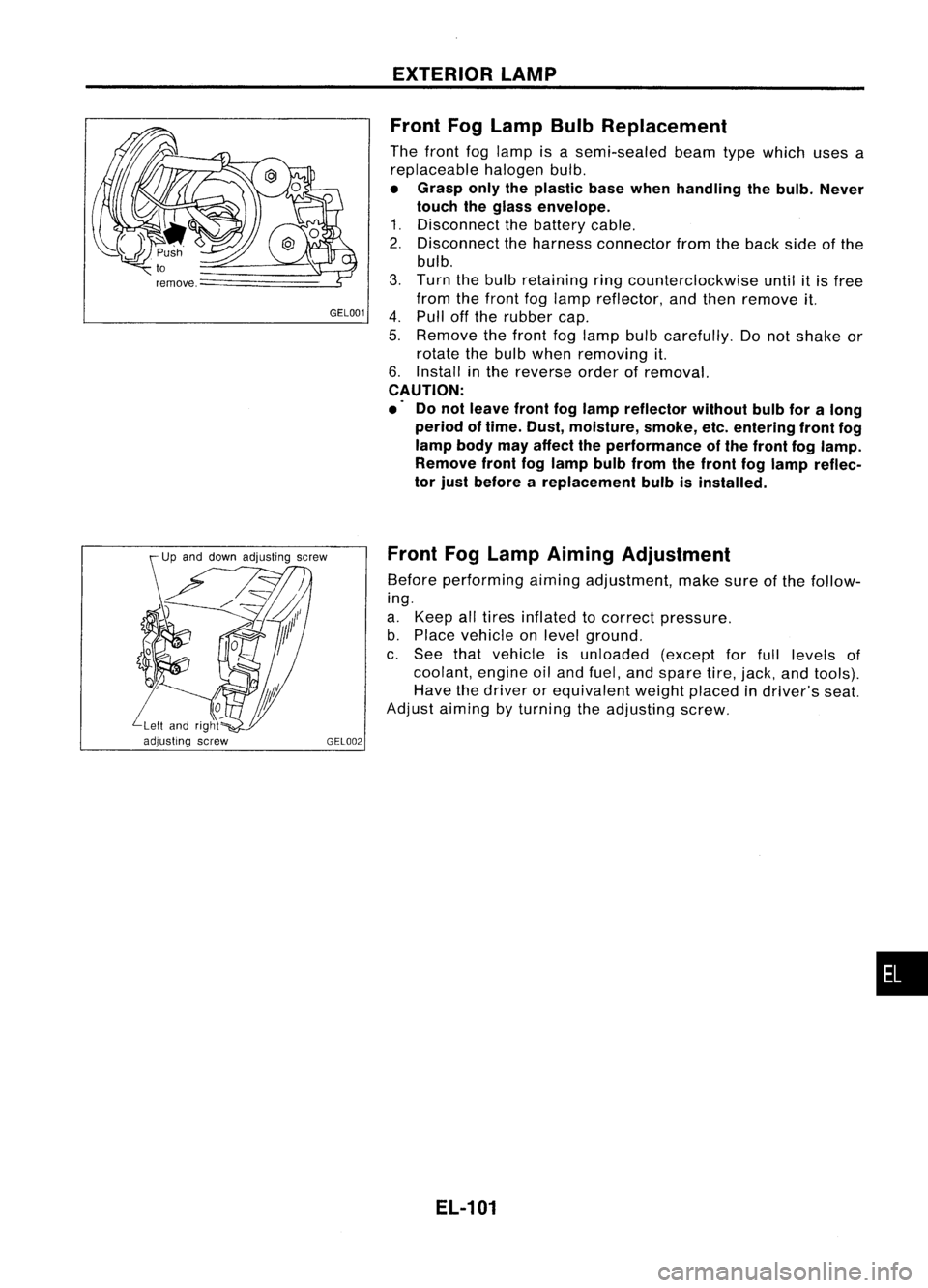
Front FogLamp BulbReplacement
The front foglamp isasemi-sealed beamtypewhich usesa
replaceable halogenbulb.
• Grasp onlytheplastic basewhen handling thebulb. Never
touch theglass envelope.
1. Disconnect thebattery cable.
2. Disconnect theharness connector fromtheback sideofthe
bulb.
3. Turn thebulb retaining ringcounterclockwise untilitis free
from thefront foglamp reflector, andthen remove it.
4. Pull offthe rubber cap.
5. Remove thefront foglamp bulbcarefully. Donot shake or
rotate thebulb when removing it.
6. Install inthe reverse orderofremoval.
CAUTION:
.' Donot leave frontfoglamp reflector withoutbulbforalong
period oftime. Dust, moisture, smoke,etc.entering frontfog
lamp bodymayaffect theperformance ofthe front foglamp.
Remove frontfoglamp bulbfrom thefront foglamp reflec-
tor just before areplacement bulbisinstalled.
Front FogLamp Aiming Adjustment
Before performing aimingadjustment, makesureofthe follow-
ing.
a. Keep alltires inflated tocorrect pressure.
b. Place vehicle onlevel ground.
c. See thatvehicle isunloaded (exceptforfull levels of
coolant, engineoiland fuel, andspare tire,jack, andtools).
Have thedriver orequivalent weightplaced indriver's seat.
Adjust aiming byturning theadjusting screw.
EL-101
•
Page 487 of 1701

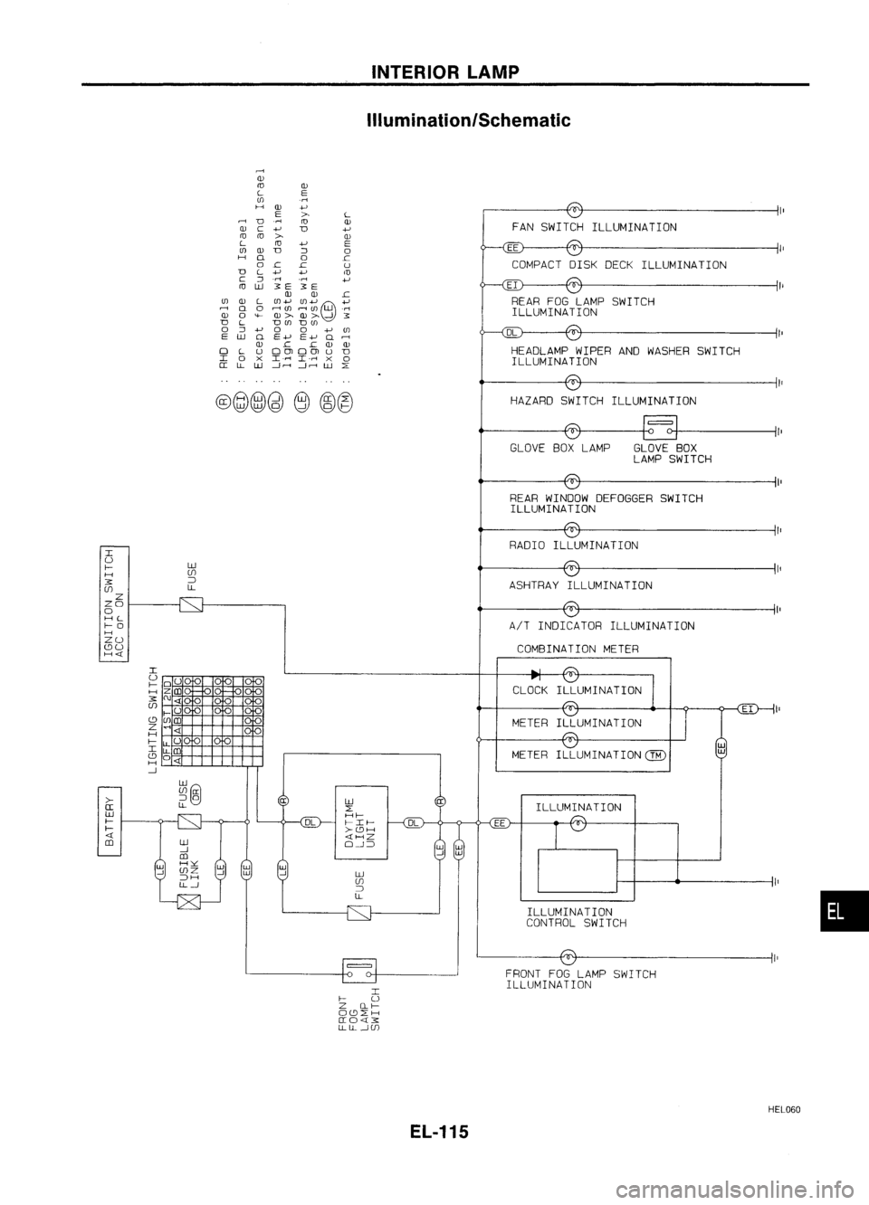
INTERIORLAMP
ilium ination/Schematic
DL
COMPACT
DISKDECK ILLUMINATION
FAN
SWITCH ILLUMINATION
HEADLAMP WIPERANDWASHER SWITCH
ILLUMINA TION
HAZARD SWITCH ILLUMINATION
EI
REAR FOGLAMP SWITCH
ILLUMINA TION
rl
Q)
ro
Q)
L
E
(J)
.rl
H
Q)
+J
E
>
L
D
.rl
ro
Q)
Q)
C
+J
D
+J
ra ra
>
Q)
L
ra
+J
E
(J)
Q)
D
::J
0
H
Q
0
.c
0
.c .c
U
D
L
+J
+J
m
c
::J
.rl
.rl
+J
ro
lLJ
3E
3E
Q) Q)
.c
(J)
Q)
L
(J)+J (J)+J
e
+J
..-;
Q
0
r-l(/)
r-1(J)
W
.rl
Q)
0
'<-
OJ> OJ>
-!
3
D
L
D(J)
D(J)
0
::J
+J
0
0
+J(J)
E
lLJ
Q
E+J E+J
Q..-;
OJ .c
.c
OJ OJ
0
L
UOOlOOlU
D
I
0
X
I.r-l
I-rl
X
0
a:
LL
lLJ
---1.---1
---1.---1
W
L:
@@@)~
e
~@
II
GLOVE BOXLAMP GLOVEBOX
LAMP SWITCH
REAR WINDOW DEFOGGER SWITCH
ILLUMINA TION
CLOCK
•
ILLUMINA
TION
ILLUMINATION
CONTROL SWITCH
METER
FRONT FOGLAMP SWITCH
ILLUMINATION
EE
lLJ
L:
Hf-
I-If-
>-cc:JH
«HZ
O-!~
RADIO
ILLUMINATION
METER
lLJ
UJ
~
LL AIT
INDICATOR ILLUMINATION
ASHTRAY
ILLUMINATION
COMBINATION METER
I
I-
U
Z Ilf-
Occ:JL:H
a:O«3:
LLLL-!UJ
lLJ
UJ
~
LL
>-
a:
lLJ
f-
f-
«
m
I
U
f-
H
3:
UJ
Z
ZO
o
HL
f-O
H
ZU
cc:JU
H«
HEL060
EL-115
Page 492 of 1701
INTERIORLAMP
Illumination/Wiring Diagram-ILL -
(Coni' d)
JUNCTION
BOX NO.2
(JOINT
CONNECTORS)
~:
JOINT
CONNECTOR-4
~:
Next
page
RIG
~ HEADLAMP
~6 WIPER AND
WASHER
SWITCH (ILLUMI-
II 7 II NATION)
L:j='
(856):
B
EL-ILL-05
: LHDmode 1s
:
RHDmodels
Models withdaytime
light system
*9 ...
13
@
3
,
1*.91
RIG
RIG
II!'I
HAZARD
SWITCH
(ILLUMI-
NATION)
~~ B
FUSE
BLOCK
(JIB)
@
IN.BI
RIG
Ii!9TI
~
RIG
t
~o
I
RIG
;2
GLOVE
BOX LAMP
~
l!4Jl
RIW
rn
IN.BI
RIG
I
RIG
REAR WINDOW
i~i
DEFOGGER
SWITCH (ILLUMINA TION)
~ ~
B
Preceding
page
~E -
ILL-02
RIG•
CLOSED GLOVE
BOX LAMP
OPEN SWITCH
~
B BB
LL
m
I1~_I;
JOINT
(
CONNECTOR- 3
_ Next~:
K page JOINT
CONNECTOR-4
---------------------' ~:
~~ ~@
[Q]~
1Irn','1Il~
alll@~
~ W
W
[IIg]
BR54213 W45231 BR
Refer
tolast page
(Foldout page).
rIIII:ITITillTI ~:
rIIII:ITITillTI ~:
~~ ~P
HEL057
EL-120
Page 549 of 1701
WIPERANDWASHER
Headlamp WiperandWasher/Wiring Diagram
-HLC-
EL-HLC-01
IGNITION SWITCH
ACC
or
ON
FUSERefertoEL-POWER.
BLOCK
(J/B)
(fi06)
15A
1291
---Ie----------- ..
•
L/Y
(~IIHEA~A~
WASHER
M MOTOR
~ ~
IIIII----------II------PU/R~}
Ibj:U ~
Nextpage
L'R
I.._
L~
L/R PU/R L/YL
m
IFh
m
IFh
L/Y
m
HEADLAMP
WIPER
MOTOR LH
MOVE
ffi
STOP
HEADLAMP
WIPER
MOTOR RH
~
MOVE
STOP
~ IbjdJ
L/W B B
L
el'
1
-----L/OR ~}
..fr:\--.....
Nextpage
L/W
.,g....-
,.
B B
~ ~
~ (E51)
~ffi.
~GY GY
Refer
tolast page •
(Foldout page).
HEL094
EL-177
Page 550 of 1701
WIPERANDWASHER
Headlamp WiperandWasher/Wiring Diagram
- HLC -(Cont'd)
EL-HLC-02
To EL-ILL. RIG
HEADLAMP
WIPER
AND WASHER
ILL SWITCH
.~
PU/R
RIG
m m
OFF
ON
ON
___ e
OFF
OFF
{~
PU/R~ PU/R
Preceding ~:~
page
1-..
~L/OR ~L/OR -----_
~ ~~
B L/WB
I~_-.--! .
•
B
~1
.JOINT
CONNECTOR-3
~
lbi=Jl
B
I
,-,
B B
~ ~
~~
~
L
..J
{~L~L
Preceding
~I~
page ~:~
-..
L/W~ L/W--------- ..
ffiII'
I'@~
45231 BR mIIIITIillIIITI
~
~BR
Refer
tolast page
(Foldout page).
HEL095
EL-178
Page 551 of 1701

.WIPER ANDWASHER
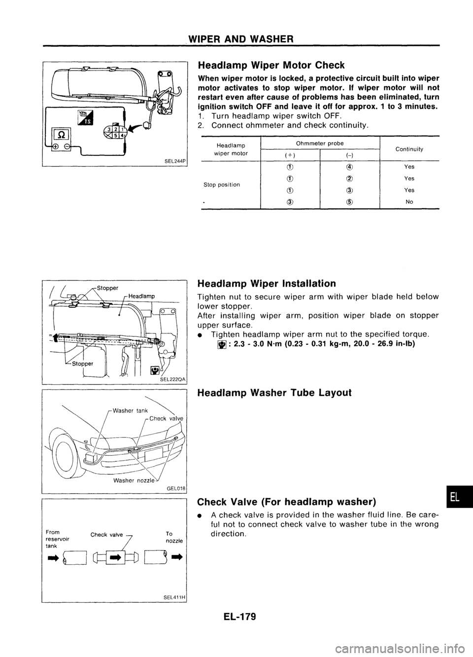
SEL244P Headlamp
WiperMotorCheck
When wiper motor islocked, aprotective circuitbuiltintowiper
motor activates tostop wiper motor. Ifwiper motor willnot
restart evenaftercause ofproblems hasbeen eliminated, turn
ignition switchOFFandleave itoff for approx. 1to 3minutes.
1. Turn headlamp wiperswitch OFF.
2. Connect ohmmeter andcheck continuity.
Headlamp Ohmmeter
probe
Continuity
wiper motor
(+)
H
(!) @
Yes
(!)
@
Yes
Stop position
(!)
CID
Yes
.
CID
@)
No
From
.. 0
c~'..
~'fo
reservoir
tank GEL018
To
nozzle
0"
SEL411H Headlamp
WiperInstallation
Tighten nuttosecure wiperarmwith wiper bladeheldbelow
lower stopper.
After installing wiperarm,position wiperbladeonstopper
upper surface.
• Tighten headlamp wiperarmnuttothe specified torque.
~ :2.3 -3.0 N'm (0.23 -0.31 kg-m, 20.0-26.9 in-Ib)
Headlamp WasherTubeLayout
Check Valve(Forheadlamp washer)
• Acheck valveisprovided inthe washer fluidline.Becare-
ful not toconnect checkvalvetowasher tubeinthe wrong
direction.
EL-179
•