Page 1491 of 1701

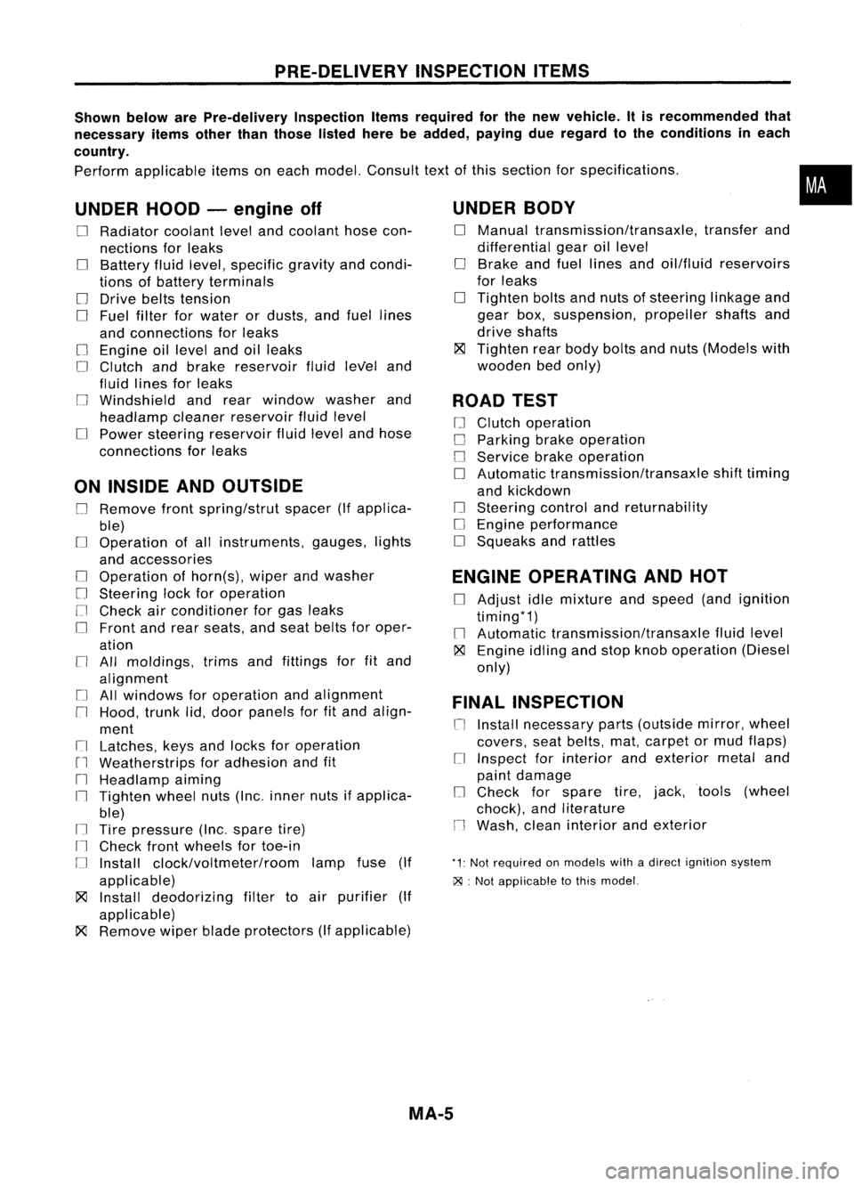
PRE-DELIVERYINSPECTIONITEMS
Shown belowarePre-delivery InspectionItemsrequired forthe new vehicle. Itis recommended that
necessary itemsotherthanthose listedherebeadded, payingdueregard tothe conditions ineach
country.
Perform applicable itemsoneach model. Consult textofthis section forspecifications .
UNDER HOOD-engine off
o
Radiator coolantlevelandcoolant hosecon-
nections forleaks
o
Battery fluidlevel, specific gravityandcondi-
tions ofbattery terminals
o
Drive beltstension
D
Fuel filter forwater ordusts, andfuel lines
and connections forleaks
[] Engine oillevel andoilleaks
D
Clutch andbrake reservoir fluidlevel and
fluid lines forleaks
o
Windshield andrear window washerand
headlamp cleanerreservoir fluidlevel
D
Power steering reservoir fluidlevel andhose
connections forleaks
ON INSIDE ANDOUTSIDE
D
Remove frontspring/strut spacer(Ifapplica-
ble)
D
Operation ofall instruments, gauges,lights
and accessories
o
Operation ofhorn(s), wiperandwasher
[] Steering lockforoperation
[] Check airconditioner forgas leaks
o
Front andrear seats, andseat belts foroper-
ation
n
All moldings, trimsandfittings forfitand
alignment
[J
Allwindows foroperation andalignment
n
Hood, trunklid,door panels forfitand align-
ment
[1
Latches, keysandlocks foroperation
rl
Weatherstrips foradhesion andfit
[l
Headlamp aiming
I~ Tighten wheelnuts(Inc. inner nutsifapplica-
ble)
IJ Tire pressure (Inc.spare tire)
Il
Check frontwheels fortoe-in
IJ Install clock/voltmeter/room lampfuse(If
applicable)
~ Install deodorizing filtertoair purifier (If
applicable)
~ Remove wiperbladeprotectors (Ifapplicable)
UNDER
BODY
o
Manual transmission/transaxle, transferand
differential gearoillevel
D
Brake andfuel lines andoil/fluid reservoirs
for leaks
D
Tighten boltsandnuts ofsteering linkageand
gear box,suspension, propellershaftsand
drive shafts
~ Tighten rearbody boltsandnuts (Models with
wooden bedonly)
ROAD TEST
D
Clutch operation
D
Parking brakeoperation
[J
Service brakeoperation
D
Automatic transmission/transaxle shifttiming
and kickdown
[] Steering controlandreturnability
o
Engine performance
D
Squeaks andrattles
ENGINE OPERATING ANDHOT
D
Adjust idlemixture andspeed (andignition
timing*1)
n
Automatic transmission/transaxle fluidlevel
~ Engine idlingandstop knob operation (Diesel
only)
FINAL INSPECTION
n
Install necessary parts(outside mirror,wheel
covers, seatbelts, mat,carpet ormud flaps)
[1
Inspect forinterior andexterior metaland
paint damage
[] Check forspare tire,jack, tools (wheel
chock), andliterature
n
Wash, cleaninterior andexterior
"1: Not required onmodels withadirect ignition system
~ :Not appiicable tothis model.
•
MA-5
Page 1498 of 1701

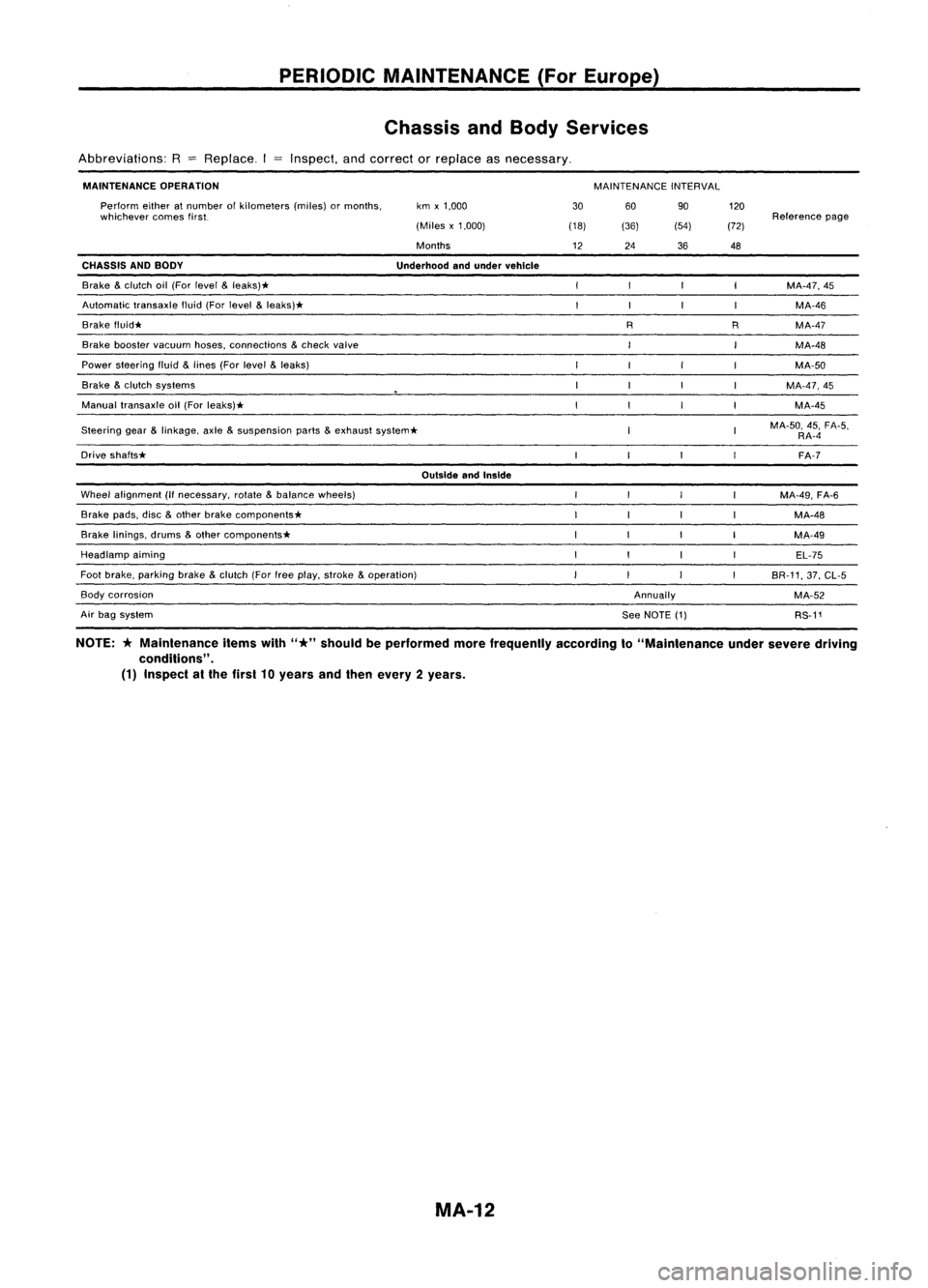
PERIODICMAINTENANCE (ForEurope)
Chassis andBody Services
Abbreviations: R
=
Replace. Inspect,andcorrect orreplace asnecessary.
MAINTENANCE OPERATION
MAINTENANCEINTERVAL
Steering gear
&
linkage, axle
&
suspension parts
&
exhaust system*
OutsideandInside
Wheel alignment (Ifnecessary, rotate
&
balance wheels)
Brake pads,disc
&
other brake components*
Brake linings, drums
&
other components*
Headlamp aiming
Foot brake, parking brake
&
clutch (Forfreeplay, stroke
&
operation)
Annually120
Reference page
(72)
48
MA-47,45MA-46
R MA-47
MA-48
MA-50
MA-47,45 MA-45
MA-50, 45,FA-5,
RA-4
FA-7
MA-49, FA-6
MA-48
MA-49 EL-75
BR-11, 37,CL-5
MA-52 RS-11
90
(54)
36
R
60
See NOTE (1)
(36)
24
30
(18)
12
km
x1,000
(Miles x1,000)
Months
Underhood andunder vehicle
Perform
eitheratnumber ofkilometers (miles)ormonths,
whichever comesfirst.
Brake booster vacuum hoses,connections
&
check valve
Brake
&
clutch oil(For level
&
leaks)*
Automatic transaxlefluid(Forlevel
&
leaks)*
Brake f1uid*
CHASSIS
ANDBODY
Power steering fluid
&
lines (Forlevel
&
leaks)
Brake
&
clutch systems
Manual transaxle oil(For leaks)*
Drive shafts*
Air bag system
Body
corrosion
NOTE:
*
Maintenance itemswith
"*"
should beperformed morefrequently accordingto"Maintenance undersevere driving
conditions" .
(1) Inspect atthe first 10years andthen every 2years.
MA-12
Page 1671 of 1701

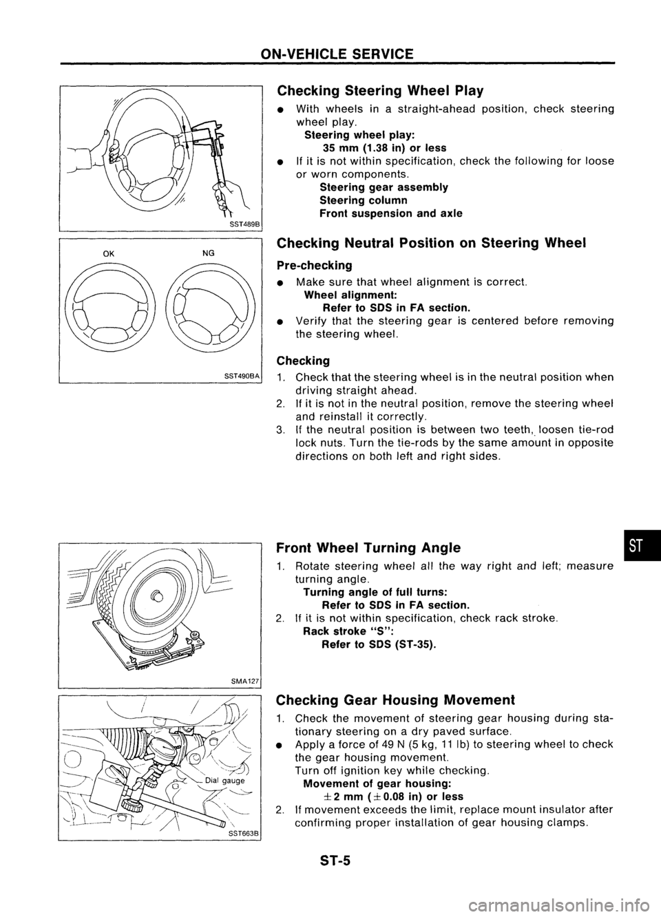
ON-VEHICLESERVICE
Checking SteeringWheelPlay
• With wheels inastraight-ahead position,checksteering
wheel play.
Steering wheelplay:
35 mm (1.38 in)orless
• Ifit is not within specification, checkthefollowing forloose
or worn components.
Steering gearassembly
Steering column
Front suspension andaxle
SST489B
OK
NGChecking
NeutralPosition onSteering Wheel
Pre-checking
• Make surethatwheel alignment iscorrect.
Wheel alignment:
Refer toSOS inFA section.
• Verify thatthesteering geariscentered beforeremoving
the steering wheel.
Checking
SST490BA
1.Check thatthesteering wheelisin the neutral position when
driving straight ahead.
2. Ifit is not inthe neutral position, removethesteering wheel
and reinstall itcorrectly.
3. Ifthe neutral position isbetween twoteeth,. loosen tie-rod
lock nuts. Turnthetie-rods bythe same amount inopposite
directions onboth leftand right sides.
Front Wheel Turning Angle •
1. Rotate steering wheelallthe way right andleft;measure
turning angle.
Turning angleoffull turns:
Refer toSOS inFA section.
2. Ifit is not within specification, checkrackstroke.
Rack stroke
"S":
Refer toSOS (ST-35).
SMA127 Checking GearHousing Movement
1. Check themovement ofsteering gearhousing duringsta-
tionary steering onadry paved surface.
• Apply aforce of49 N(5 kg, 11Ib) tosteering wheeltocheck
the gear housing movement.
Turn offignition keywhile checking.
Movement ofgear housing:
:I:
2 mm
(:I:
0.08 in)orless
2. Ifmovement exceedsthelimit, replace mountinsulator after
confirming properinstallation ofgear housing clamps.
ST-5
Page 1676 of 1701
STEERINGWHEELANDSTEERING COLUMN
Removal andInstallation (Cont'd)
• Align spiral cablecorrectly wheninstalling steeringwheel.
a. Set thefront wheels inthe straight-ahead position.
b. Make surethatthespiral cableisin the neutral position.
\ Theneutral position isdetected byturning left2.5revolu-
~ tionsfromtheright endposition. Alignthetwo marks (~').
CAUTION:
The spiral cablemaysnap duetosteering operation ifthe cable
is installed inan improper position.
Also, withthesteering linkagedisconnected, thecable may
snap byturning thesteering wheelbeyond thelimited number
of turns. (Thespiral cablecanbeturned upto2.5 turns fromthe
neutral position toboth theright andleft.)
MBF487BA
•Remove steering wheelwithTool.
Without AirBag
1. Remove hornpad.
Insert acrosshead screwdriver intohole onlower sideof
spoke andremove clamp.
Lift
horn padoffbyhand.
Three spoke type
Cross headscrewdriver SST502C
SST495CA ST-10
Page 1677 of 1701
STEERINGWHEELANDSTEERING COLUMN
Removal andInstallation (Cont'd)
Two spoke type
Clamp
Crosshead screwdriver~
II
SST503C
2.Remove steering wheelwithTool.
SST122B
Cr~I~I;~
~#f
~.'".
Lowerjoint
SST112B
SST800A
•
When installing steeringwheel,lubricate withmulti-purpose
grease. Applygrease toentire surface ofturn signal cancel
pins andhorn contact sliprings.
STEERING COLUMN
• When installing steeringcolumn,fingertighten alllower
bracket andclamp retaining bolts;thentighten them
securely. Donot apply undue stress tosteering column.
• When attaching couplingjoint,besure tightening boltfaces
cutout portion.
• Align slitoflower jointwithprojection ondust cover. Insert
joint untilsurface Acontacts surfaceB.
CAUTION:
After installation, turnsteering wheeltomake sureitmoves
smoothly. Ensurethenumber ofturns arethesame fromthe
straight forward position toleft and right locks. Besure thatthe
steering wheelisin aneutral position whendriving straight
ahead.
•
SST491C ST-11
Page 1680 of 1701
MANUALSTEERING GEARANDLINKAGE (ModelR24N)
Removal andInstallation
SEC. 480
A :
N.m (kg-m, tt-Ib)
(!)
Hole cover
@
Lower joint
@
Manual steering gearassembly
@
Steering gearmounting clamp
tt'J
29•39
(3.0 -4.0,22 -", ~
~
@~ SST056CA
@
Rack mounting insulator
@
Cotter pin
CAUTION:
The rotation ofthe spiral cable(SRS"Airbag" component part)
is limited.
If
the steering gearmust beremoved, setthe front
wheels inthe straight-ahead direction.Donot rotate thesteer-
ing column whilethesteering gearisremoved.
• Detach tie-rodoutersockets fromknuckle armswithTool.
• Initially, tightennutontie-rod outersocket andknuckle arm
to 29 to39 N'm (3to 4kg-m, 22to29 ft-Ib).
• Tighten nutfurther toalign nutgroove withthefirst pinhole
so cotter pincan beinstalled.
CAUTION:
Tightening torquemustnotexceed 49N.m (5kg-m, 36ft-Ib).
ST-14
Page 1693 of 1701

POWERSTEERING GEARANDLINKAGE (ModelPR24AC)
Assembly (Cont'd)
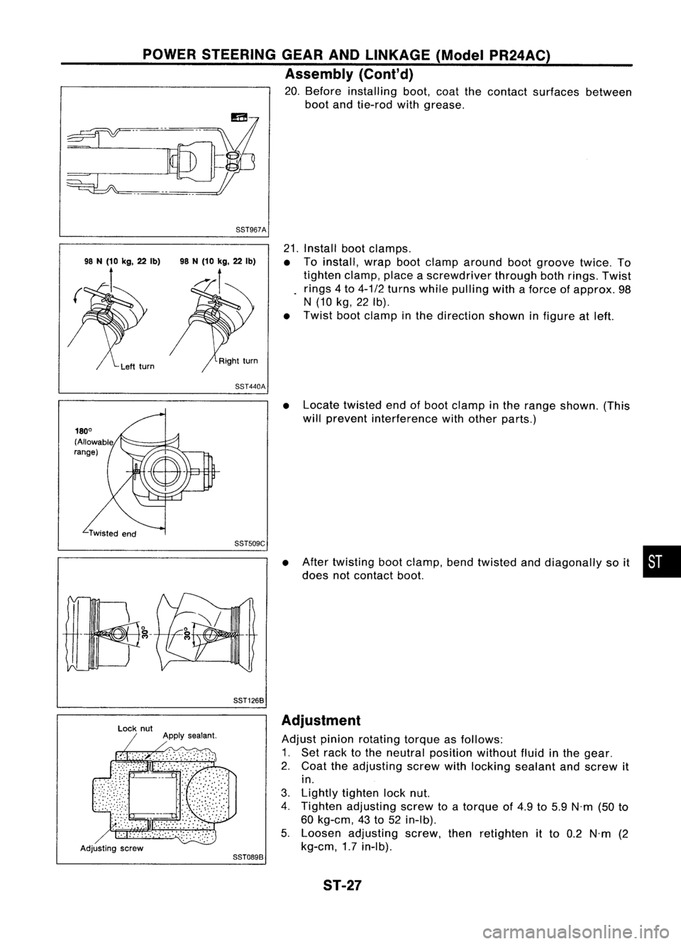
20. Before installing boot,coatthecontact surfaces between
boot andtie-rod withgrease.
88T967A
21.Install bootclamps.
• Toinstall, wrapbootclamp around bootgroove twice.To
tighten clamp,placeascrewdriver throughbothrings. Twist
rings 4to 4-1/2 turns while pulling withaforce ofapprox. 98
N (10 kg,22Ib).
• Twist bootclamp inthe direction showninfigure atleft.
88T440A
•Locate twisted endofboot clamp inthe range shown. (This
will prevent interference withother parts.)
88TS09C
88T1268
•
After twisting bootclamp, bendtwisted anddiagonally soit •
does notcontact boot.
Adjusting screw
88T0898Adjustment
Adjust pinionrotating torqueasfollows:
1. Set rack tothe neutral position withoutfluidinthe gear.
2. Coat theadjusting screwwithlocking sealant andscrew it
in.
3. Lightly tighten locknut.
4. Tighten adjusting screwtoatorque of4.9 to5.9 N'm (50to
60 kg-em, 43to52 in-Ib).
5. Loosen adjusting screw,thenretighten itto 0.2 N'm (2
kg-em, 1.7in-Ib).
ST-27