Page 145 of 1701
SAT341D
SAT438D
SAT439D
KV31101300 NAT064 ASSEMBLY
Adjustment 1(Cont'd)
OUTPUT SHAFTENDPLAY
- Model 34X81-
• Measure clearance betweensidecover andtheend ofthe
output shaftbearing.
• Select proper thickness ofadjusting shimsothat clearance
is within specifications.
1. Install bearing retainer foroutput shaft.
2. Install output shaftthrust needle bearing onbearing •
retainer.
3. Install output shaftontransmission case.
4. Measure dimensions"
£1"
and"
£2"
atside cover andthen
calculate dimension "A".
• Measure dimension
"f/'
and
"f
2"
inat least twoplaces.
"A":
Distance betweentransmission casefitting surface
and adjusting shimmating surface.
A
= f
1-£2 £2:
Height ofgauge
AT-145
Page 146 of 1701

SAT440DASSEMBLY
Adjustment 1(Cont'd)
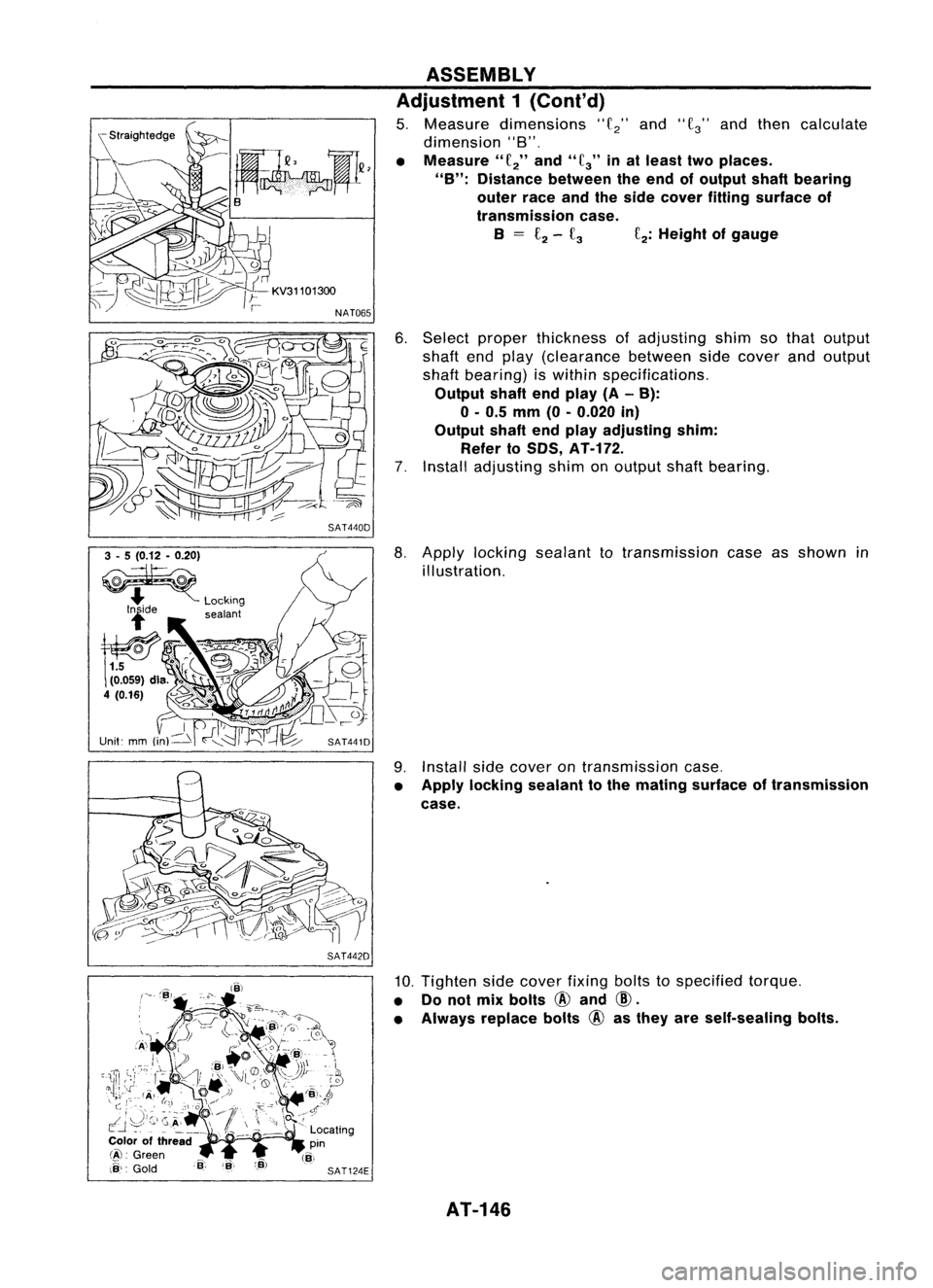
5. Measure dimensions
"f
2"
and
"f
3"
andthen calculate
dimension "8".
• Measure"
f
2"
and"
fa"
inat least twoplaces.
"B": Distance betweentheend ofoutput shaftbearing
outer raceandtheside cover fitting surface of
transmission case.
B
=
£2-
fa
f
2:
Height ofgauge
6. Select proper thickness ofadjusting shimsothat output
shaft endplay (clearance betweensidecover andoutput
shaft bearing) iswithin specifications.
Output shaftendplay (A-B):
o -
0.5
mm
(0-0.020
in)
Output shaftendplay adjusting shim:
Refer to50S,
AT-H2.
7. Install adjusting shimonoutput shaftbearing.
3 -5 (0.12 -0.20)
~
.... Locking
lide sealant
SAT441D
SAT442D
8.
Apply locking sealant totransmission caseasshown in
illustration.
9. Install sidecover ontransmission case.
• Apply locking sealant tothe mating surface oftransmission
case.
10. Tighten sidecover fixingboltstospecified torque.
• Donot mix bolts
@
and
CID.
• Always replace bolts
@
asthey areself-sealing bolts.
AT-146
Page 281 of 1701
SEC.465
iii :
N'm (kg-m, in-Ib)
~ :N'm (kg-m, ft-Ib)
BRAKE
PEDALANDBRACKET
Removal andInstallation
Sloplamp sWitch
SBR205D
o
Inspection
Check brakepedalforfollowing items:
• Brake pedalbend
• Clevis pindeformation
• Crack ofany welded portion
• Crack ordeformation ofclevis pinstopper
•
SBR997
Adjustment
Check brakepedalfreeheight fromdash reinforcement panel
(RHD) anddash lower panel (LHD). Adjust ifnecessary.
H: Freeheight
Refer to
50S
(BR-SS).
0: Depressed height
Refer to
50S
(BR-SS).
Under forceof
490
N
(50
kg,
110
Ib)
with engine running
1. Loosen locknutand adjust pedalfreeheight byturning
brake booster inputrod.Then tighten locknut.
2. Check pedalfreeplay.
Make surethatstop lamps gooff when pedal isreleased.
3. Check brakepedal's depressed heightwhileengine isrun-
ning. If lower thanspecification, checkforleaks, airinsystem or
damage tocomponents (mastercylinder, wheelcylinder,
etc.). Then make necessary repairs.
SBR034D BR-11
Page 358 of 1701

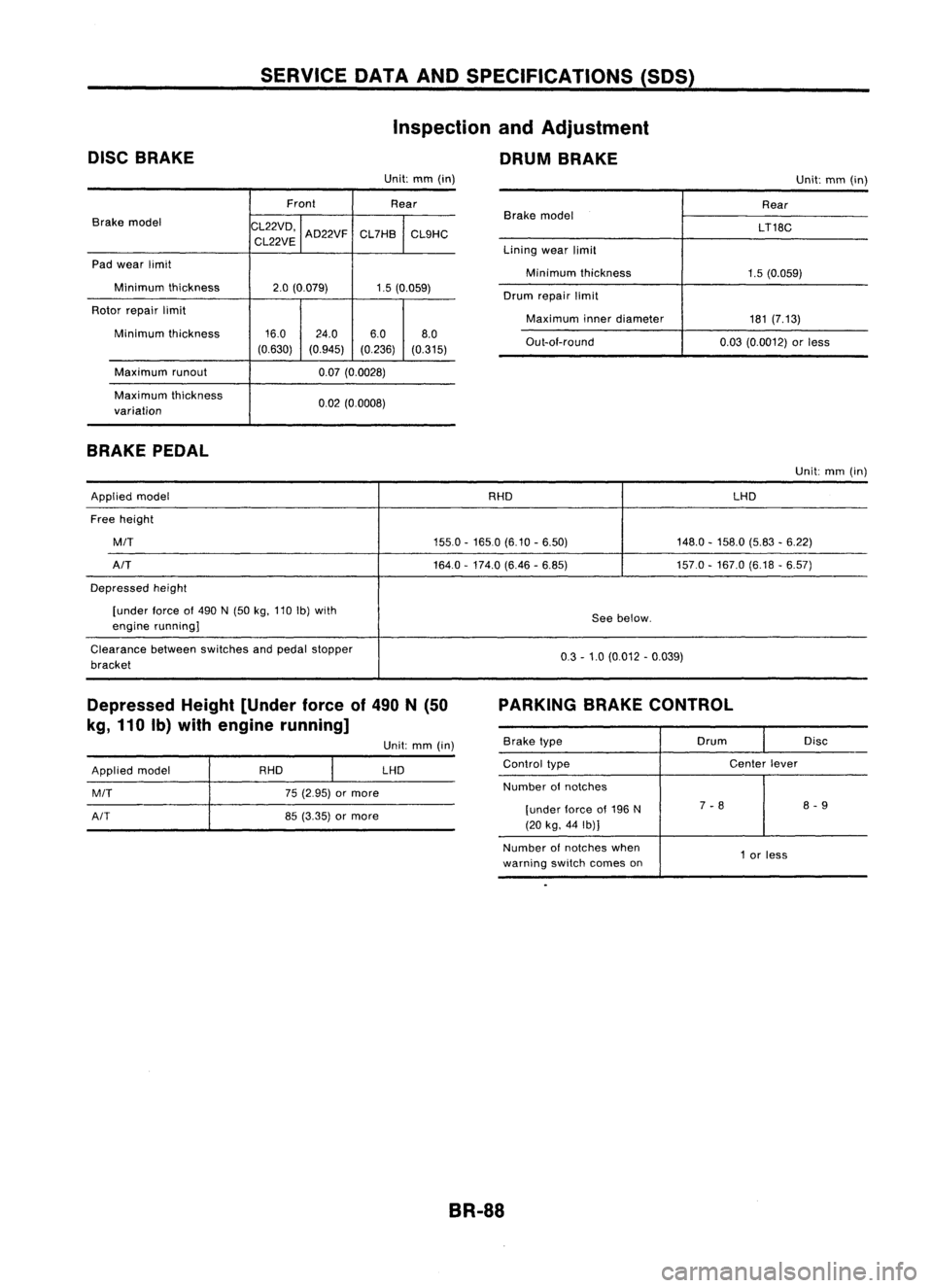
DISCBRAKE SERVICE
DATAANDSPECIFICATIONS (SDS)
Inspection andAdjustment
DRUM BRAKE
Unit: mm(in)
Unit:mm(in)
Front Rear
Brake model
CL22VD,
CL22VE AD22VF
CL7HB
CL9HC
Pad wear limit
Minimum thickness
2.0(0.079) 1.5(0.059)
Rotor repair limit
Minimum thickness 16.0
24.0 6.08.0
(0.630) (0.945) (0.236)(0.315)
Maximum runout 0.07(0.0028)
Maximum thickness
0.02(0.0008)
variation
BRAKE PEDAL
Brake
model
Lining wearlimit
Minimum thickness
Drum repair limit
Maximum innerdiameter
Out-ai-round Rear
LT18C
1.5 (0.059)
181 (7.13)
0.03 (0.0012) orless
Unit: mm(in)
Applied model RHDLHD
Free height
MIT
155.0-1650 (6.10-6.50) 148.0-158.0 (5.83-6.22)
AIT
164.0-174.0 (6.46-6.85) 157.0-167.0 (6.18-6.57)
Depressed height
[under force
01
490 N(50 kg,110 Ib)with
Seebelow.
engine running]
Clearance betweenswitches andpedal stopper
0.3-1.0 (0.012 -0.039)
bracket
Depressed Height[Under forceof490 N(50
kg, 110 Ib)with engine running] PARKING
BRAKECONTROL
Applied model
MIT
AIT
RHD
75(2.95) ormore
85 (3.35) ormore Unit:
mm(in)
LHD
Brake
type Drum
Disc
Control type Center
lever
Number
01
notches
[under lorceof196 N 7
-8 8
-9
(20 kg, 44Ib)]
Number ofnotches when
1or less
warning switchcomes on
BR-88
Page 363 of 1701

INSPECTIONANDADJUSTMENT
Pedal stopper
Dash lower
panel (except
CD20 engine //
model)
/L
Floor car-pet
L
Dash reinforcement panel
(CD20 engine model)
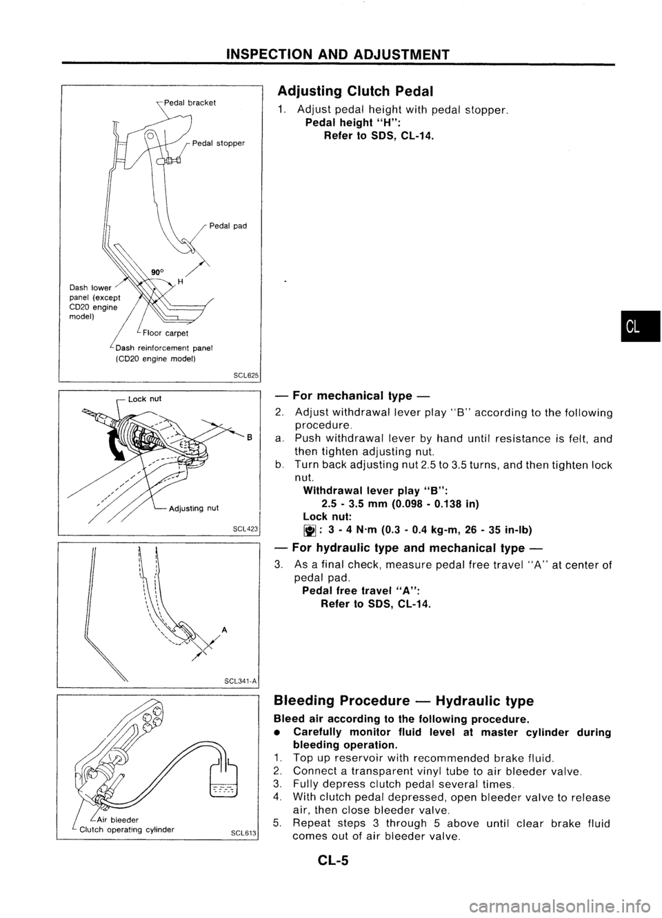
Adjusting
ClutchPedal
1. Adjust pedalheight withpedal stopper.
Pedal height
"H":
Refer to
50S,
CL-14.
•
SCL625
SCL423 -
For mechanical type-
2. Adjust withdrawal leverplay"8"according tothe following
procedure_
a. Push withdrawal leverbyhand untilresistance isfelt, and
then tighten adjusting nut.
b. Turn backadjusting nut2.5to3.5 turns, andthen tighten lock
nut.
Withdrawal leverplay
"B":
2.5 -3.5 mm (0.098 -0.138 in)
lock nut:
~: 3-
4 N'm (0.3-0.4 kg-m, 26-35 in-Ib)
- For hydraulic typeandmechanical type-
3. Asafinal check, measure pedalfreetravel "A"atcenter of
pedal pad.
Pedal freetravel
"A":
Refer to
50S,
CL-14.
B
Bleeding Procedure -Hydraulic type
Bleed airaccording tothe following procedure.
• Carefully monitorfluidlevel atmaster cylinder during
bleeding operation.
1. Top upreservoir withrecommended brakefluid.
2. Connect atransparent vinyltubetoair bleeder valve.
3. Fully depress clutchpedalseveral times.
4. With clutch pedaldepressed, openbleeder valvetorelease
air, then close bleeder valve.
5. Repeat steps3through 5above untilclear brake fluid
SCL613
comesoutofair bleeder valve.
SCL341-A
Adjusting
nut
Lock
nut
CL-5
Page 370 of 1701

CLUTCHDISCANDCLUTCH COVER
Clutch Disc(Cont'd)
INSTALLATION
• Apply recommended greasetocontact surface ofsplines.
• Too much lubricant maydamage clutchdiscfacing.
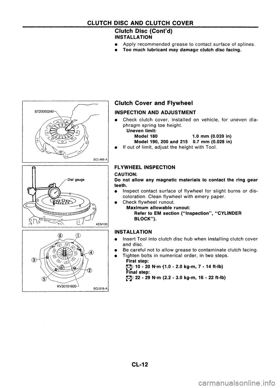
Dial gauge Clutch
CoverandFlywheel
INSPECTION ANDADJUSTMENT
• Check clutchcover, installed onvehicle, foruneven dia-
phragm springtoeheight.
Uneven limit:
Model 180 1.0mm (0.039 in)
Model 190,
200and 215 0.7mm (0.028 in)
• Ifout oflimit, adjust theheight withTool.
SCL466-A FLYWHEEL INSPECTION
CAUTION:
Do not allow anymagnetic materials tocontact thering gear
teeth.
• Inspect contact surface offlywheel forslight burns ordis-
coloration. Cleanflywheel withemery paper.
• Check flywheel runout.
Maximum allowable runout:
Refer toEM section ("Inspection", "CYLINDER
BLOCK").
AEM100
INSTALLATION
• Insert Toolintoclutch dischubwhen installing clutchcover
and disc.
• Becareful nottoallow grease tocontaminate clutchfacing.
• Tighten boltsinnumerical order,intwo steps.
First step:
~: 10•20 N'm '(1.0 •2.0 kg-m, 7-14 ft-Ib)
Final step:
~: 22•29 N'm (2.2•3.0 kg-m, 16•22 ft-Ib)
SCL616-A
CL-12
Page 372 of 1701
SERVICEDATAANDSPECIFICATIONS (SOS)
Inspection andAdjustment
CLUTCH PEDAL
Unit:mm(in)
Except forCD20 engine models
CD20engine models
Applied model
RHOLHD
RHO LHD
Pedal height "H"
159-169 (6.26 -6.65)'1 153-163 (6.02 -6.42)*2 156-166 (6.14 -6.54)'1
149-159 (5.87 -6.26)'2
Pedal freetravel "A"
11-15 (0.43 -0.59)
9-16 (0.35 -0.63)
(at pedal pad)
Withdrawal leverplay"8" 2.5-3.5 (0.098 -0.138)
-
'1: Measured fromsurface ofdash reinforcement paneltosurface ofpedal pad.
'2: Measured fromsurface ofdash lower paneltosurface ofpedal pad.
CLUTCH DISC
Unit:mm(in)
Disc model
180190
I
200
215
Wear limitoffacing surface torivet head
0.3(0.012)
Runout limitoffacing 1.0(0.039)
Distance ofrunout checkpoint(from hub
85(3.35) 90(3.54)
I
95
(3.74) 102.5(4.04)
center)
Maximum backlashofspline (atouter edgeof
0.7(0.028) 0.8(0.031)
0.9(0.035)
disc)
CLUTCH COVER
Cover model
Uneven limitofdiaphragm springtoeheight 180
1.0 (0.039)
CL-14 190
I
200
0.7 (0.028)
I
Unit:
mm(in)
215
Page 448 of 1701
-
Up and down adjusting screw
, \ ,I/
MEL614DHEADLAMP
Aiming Adjustment (Cont'd)
LOW BEAM
1. Turn headlamp lowbeam on.
2. Use adjusting screwstoperform aimingadjustment.
• First tighten theadjusting screwallthe way andthen make
adjustment byloosening thescrew.
• Adjust headlamps sothat main axisoflight isparallel to
center lineofbody andisaligned withpoint Pshown in
illustration.
• Figure tothe leftshows headlamp aiming pattern fordriv-
ing onright sideofroad; fordriving onleft side ofroad,
aiming pattern isreversed.
• Dotted linesinillustration showcenter ofhead lamp.
"H":
Horizontal centerlineofheadlamps
"W
L":
Distance betweeneachheadlamp center
"l":
5,000mm(196.85 in)
"e":
65mm (2.56 in)
Height of
lamp centers
I
f
P \
/~
Vertical
centerline
ahead ofheadlamps -
"H":
Horizontal
center line
of headlamps
d
=
ACCEPTABLE RANGE
SEL2541
EL-76