1995 NISSAN ALMERA N15 compression ratio
[x] Cancel search: compression ratioPage 754 of 1701

BASICSERVICE PROCEDURE
Idle Speedllgnition TiminglldleMixtureRatio
Adjustment
PREPARATION
• Make surethatthefollowing partsarein
good order.
(1) Battery
(2) Ignition system
(3) Engine oiland coolant levels
(4) Fuses
(5) ECM harness connector
(6) Vacuum hoses
(7) Airintake system
(Oil filler cap,oillevel gauge, etc.)
(8) Fuel pressure
(9)' Engine compression
(10) Throttle valve
(11) EGR valve operation -For Europe and
Israel andAustralia, andGA15DE M/Tmod-
els
Overall inspection sequence
INSPECTION
(12)
Evaporative emissionsystem
• On models equipped withairconditioner,
checks shouldbecarried outwhile theair
conditioner is"OFF".
• On models equipped withautomatic
transaxle, whenchecking idlespeed, ignition
timing andmixture ratio,checks shouldbe
carried outwhile shiftlever isin
"N"
position.
• When measuring
"CO"
percentage, insert
probe morethan40cm (15.7 in)into tailpipe .•
• Turn offheadlamps, heaterblower, rear
defogger.
• Keep frontwheels pointed straight ahead.
• Make thecheck afterthecooling fanhas
stopped.
Perform diagnostic testmode
1/
(Self-diagnostic results).
Check
&
adjust ignition timing.
Check
&
adjust idlespeed. NG
Repair orreplace.
Check oxygen sensor*1 function.
OK
Check
oxygen sensor*1 har-
ness.
Check CO%.
NG
NG
Repair orreplace harness.
OK Replace oxygensensor*1.
INSPECTION END Check
emission controlparts NGCheck oxygen sensor*1 function. OK
and repair orreplace ifneces-
sary.
*1: Heated oxygen sensor(ForEurope andIsrael, andAustralia AfTmodels)
Oxygen sensor(Except forEurope andIsrael, andAustralia AfTmodels)
EC-35
Page 772 of 1701

ON-BOARDDIAGNOSTIC SYSTEMDESCRIPTION
CONSULT (Cont'd)
ACTIVE TESTMODE
TEST ITEM CONDITION JUDGEMENT
CHECKITEM(REMEDY)
• Engine: Returntothe original
•Harness andconnector
FUEL INJECTION trouble
condition If
trouble symptom disappears,
•Fuel injectors
• Change theamount offuel see
CHECK ITEM.
injection usingCONSULT . •
Oxygen sensor*1
• Engine: Afterwarming up,idle
IACV-AACIV the
engine.
Enginespeedchanges according •Harness andconnector
OPENING •
Change theIACV-AAC valve
tothe opening percent. •
IACV-AAC valve
opening percentusingCON-
SULT.
• Engine: Returntothe original
•Harness andconnector
ENG COOLANT trouble
condition
Iftrouble symptom disappears, •
Engine coolant temperature
TEMP •
Change theengine coolant
.
see CHECK ITEM. sensor
temperature indicationusing
•Fuel injectors
CONSULT.
• Engine: Returntothe original
trouble condition
Iftrouble symptom disappears,
IGNITION TIMING•
Timing light:Set •
Adjust initialignition timing
• Retard theignition timingusingsee
CHECK ITEM.
CONSULT .
• Engine: Afterwarming up,idle •
Harness andconnector
the engine. •
Compression
POWER •
A/C switch "OFF"
Enginerunsrough ordies . •
Injectors
BALANCE •
Shift lever "N" •
Power transistor
• Cut offeach injector signalone •
Spark plugs
at atime using CONSULT. •
Ignition coils
• Ignition switch:ON
COOLING FAN*3•
Turn thecooling fan"ON" and
Cooling fanmoves andstops. •
Harness andconnector
"OFF", or"LOW" and"HI" •
Cooling fanmotor
and "OFF" usingCONSULT .
• Ignition switch:ON(Engine
FUEL PUMP stopped)
Fuelpump relaymakes theoper- •Harness andconnector
• Turn thefuel pump relay"ON"
RELAY and"OFF" usingCONSULT ating
sound. •
Fuel pump relay
and listen tooperating sound.
EGRC SOLENOID
VALVE (EVAP canister
•Ignition switch:ON
purge control
•Turn solenoid valve"ON" and Solenoid
valvemakes anoperat- •
Harness andconnector
solenoid valveor
EGR valve
&
"OFF"
withtheCONSULT andingsound. •
Solenoid valve
EVAP canister listen
tooperating sound.
purge control
solenoid valve)
•Ignition switch:ON
VALVE TIMING •
Turn solenoid valve"ON" and Solenoid
valvemakes anoperat- •
Harness andconnector
SOL*2 "OFF"
usingCONSULT anding
sound. •
Solenoid valve
listen tooperating sound.
SELF-LEARNING •
Inthis test, thecoefficient ofself-learning controlmixture ratioreturns tothe original coefficient by
CONT touching
"CLEAR" onthe screen.
*1: Heated oxygen sensor(ForEurope andIsrael, andAustralia A/Tmodels)
Oxygen sensor(Except forEurope andIsrael, andAustralia A/Tmodels)
*2: GA16DE except forEurope andIsrael
*3: GA16DE engine A/Tmodels forEurope without heavydutykithave a2- step control [ON/OFF] system."LOW"and"HI"
are shown onCONSULT screentorepresent "ON"condition.
EC-53
•
Page 775 of 1701

ON-BOARDDIAGNOSTIC SYSTEMDESCRIPTION
CONSULT (Cont'd)
FUNCTION TEST
CONDITION JUDGEMENTCHECKITEM(REMEDY)
ITEM
•After warming up,idle the
engine .
• Injector operation ofeach •Injector circuit(Injector,
cylinder isstopped one harnessorconnector)
after another, andresult-
Difference inengine speedisgreater •
Ignition circuit(Spark
POWER BALANCE ant
change inengine rota-
than25rpm before andafter cutting off plug,
power transistor,
lion isexamined toevalu-
theinjector ofeach cylinder. ignition
coil,harness or
ate combustion ofeach connector)
cylinder. (Thisisonly dis- •Compression
played formodels wherea •
Valve timing
sequential multiportfuel
injection systemisused.)
• After warming up,idle the
•Harness andconnector
engine. •IACV-AAC valve
• IACV-AAC valvesystem is
Difference inengine speedisgreater •
Air passage restriction
IACV-AACIV testedbydetecting change
than150rpm between whenvalveopen- betweenairinlet and
SYSTEM inengine speedwhen
ingisat 80% andat20%. IACV-AACvalve
IACV-AAC valveopening
•IAS (Idle adjusting screw)
is changed to0%, 20%
and 80%. adjustment
EC-56
Page 962 of 1701

BASICSERVICE PROCEDURE
Idle Speedllgnition TiminglldleMixtureRatio
Adjustment
PREPARATION
• Make surethatthefollowing partsarein
good order.
(1) Battery
(2) Ignition system
(3) Engine oiland coolant levels
(4) Fuses
(5) ECM harness connector
(6) Vacuum hoses
(7) Airintake system
(Oil filler cap,oillevel gauge, etc.)
(8) Fuel pressure
(9) Engine compression
(10) Throttle valve
Overall inspection sequence
INSPECTION
•
•
•
•
•
•
On
models equipped withairconditioner,
checks shouldbecarried outwhile theair
conditioner is"OFF".
On models equipped withautomatic
transaxle, whenchecking idlespeed, ignition
timing andmixture ratio,checks shouldbe
carried outwhile shiftlever isin "N" position.
When measuring "CO"percentage, insert
probe morethan40cm (15.7 in)into tailpipe.
Turn offheadlamps, heaterblower, rear
defogger. Keep frontwheels pointed straight ahead.
Make thecheck afterthecooling fanhas
stopped.
•
Perform diagnostic testmode II
(Self-diagnostic results).
OK
Check
&
adjust ignition timing.
Check
&
adjust idlespeed.
Check heated oxygen sensor
function. NG
Repair orreplace.
NG Check heated oxygen sensor
harness. NG
Repair orreplace harness.
OK OK
Check CO%. OKReplace heatedoxygen sensor.
NG
INSPECTION END Check
emission controlparts
and repair orreplace ifneces-
sary.
EC-243
NG
Check heated oxygen sensor
function.
OK
Page 978 of 1701

ON-BOARDDIAGNOSTIC SYSTEMDESCRIPTION
CONSULT (Conl'd)
ACTIVE TESTMODE
TEST ITEM CONDITION JUDGEMENTCHECKITEM(REMEDY)
• Engine: Returntothe original
•Harness andconnector
FUEL INJECTION trouble
condition
Iftrouble symptom disappears,
•Fuel injectors
• Change theamount offuel
seeCHECK ITEM.
•Heated oxygen sensor
injection usingCONSULT .
• Engine: Afterwarming up,idle
IACV-AACIV the
engine.
Enginespeedchanges according •Harness andconnector
OPENING •
Change theIACV-AAC valve
tothe opening percent. •
IACV-AAC valve
opening percentusingCON-
SULT.
• Engine: Returntothe original
•Harness andconnector
ENG COOLANT trouble
condition
Iftrouble symptom disappears, •
Engine coolant temperature
• Change theengine coolant
.
TEMP see
CHECK ITEM. sensor
temperature indicationusing
•Fuel injectors
CONSULT .
• Engine: Returntothe original
trouble condition
Iftrouble symptom disappears,
IGNITION TIMING•Timing light:Set •
Adjust initialignition timing
• Retard theignition timingusingsee
CHECK ITEM.
CONSULT.
• Engine: Afterwarming up,idle •
Harness andconnector
the engine. •
Compression
POWER
•
AIC
switch "OFF"
Enginerunsrough ordies. •
Injectors
BALANCE •
Shift lever "N" •
Power transistor
• Cut offeach injector signalone •
Spark plugs
at atime using CONSULT . •
Ignition coils
• Ignition switch:ON
•Harness andconnector
COOLING FAN•
Turn thecooling fan"ON" andCooling
fanmoves andstops.
•Cooling fanmotor
"OFF" usingCONSULT .
• Ignition switch:ON(Engine
FUEL PUMP stopped)
Fuelpump relaymakes theoper- •
Harness andconnector
RELAY •
Turn thefuel pump relay"ON"
atingsound. •
Fuel pump relay
and "OFF" usingCONSULT
and listen tooperating sound.
EGRC •
Ignition switch:ON
• Turn solenoid valve"ON"and Solenoid
valvemakes anoperat- •
Harness andconnector
SOLENOID "OFF"withtheCONSULT andingsound. •
Solenoid valve
VALVE listentooperating sound.
SELF-LEARNING •
In this test, thecoefficient ofself-learning controlmixture ratioreturns tothe original coefficient by
CONT touching
"CLEAR" onthe screen.
EC-259
•
Page 981 of 1701

ON-BOARDDIAGNOSTIC SYSTEMDESCRIPTION
CONSULT (Cont'd)
FUNCTION TEST
CONDITION JUDGEMENTCHECKITEM(REMEDY)
ITEM
•After warming up,idle the
engine.
• Injector operation ofeach •Injector circuit(Injector,
cylinder isstopped one harness
orconnector)
after another, andresult-
Difference inengine speedisgreater •
Ignition circuit(Spark
ant change inengine rota- plug,
power transistor,
POWER BALANCE
tionisexamined toevalu- than
25rpm before andafter cutting off
ignition coil,harness or
ate combustion ofeach the
injector ofeach cylinder.
connector)
cylinder. (Thisisonly dis- •
Compression
played formodels wherea •
Valve timing
sequential multiportfuel
injection systemisused.)
• After warming up,idle the
•Harness andconnector
engine. •IACV-AAC
valve
• IACV-AAC valvesystem is
Difference inengine speedisgreater •
Air passage restriction
IACV-AACIV testedbydetecting change
than150rpm between whenvalve open- between
airinlet and
SYSTEM inengine speedwhen
ingisat 80% andat20%. IACV-AAC
valve
IACV-AAC valveopening
•IAS (Idle adjusting screw)
is changed to0%,20%
adjustment
and 80%.
EC-262
Page 1093 of 1701

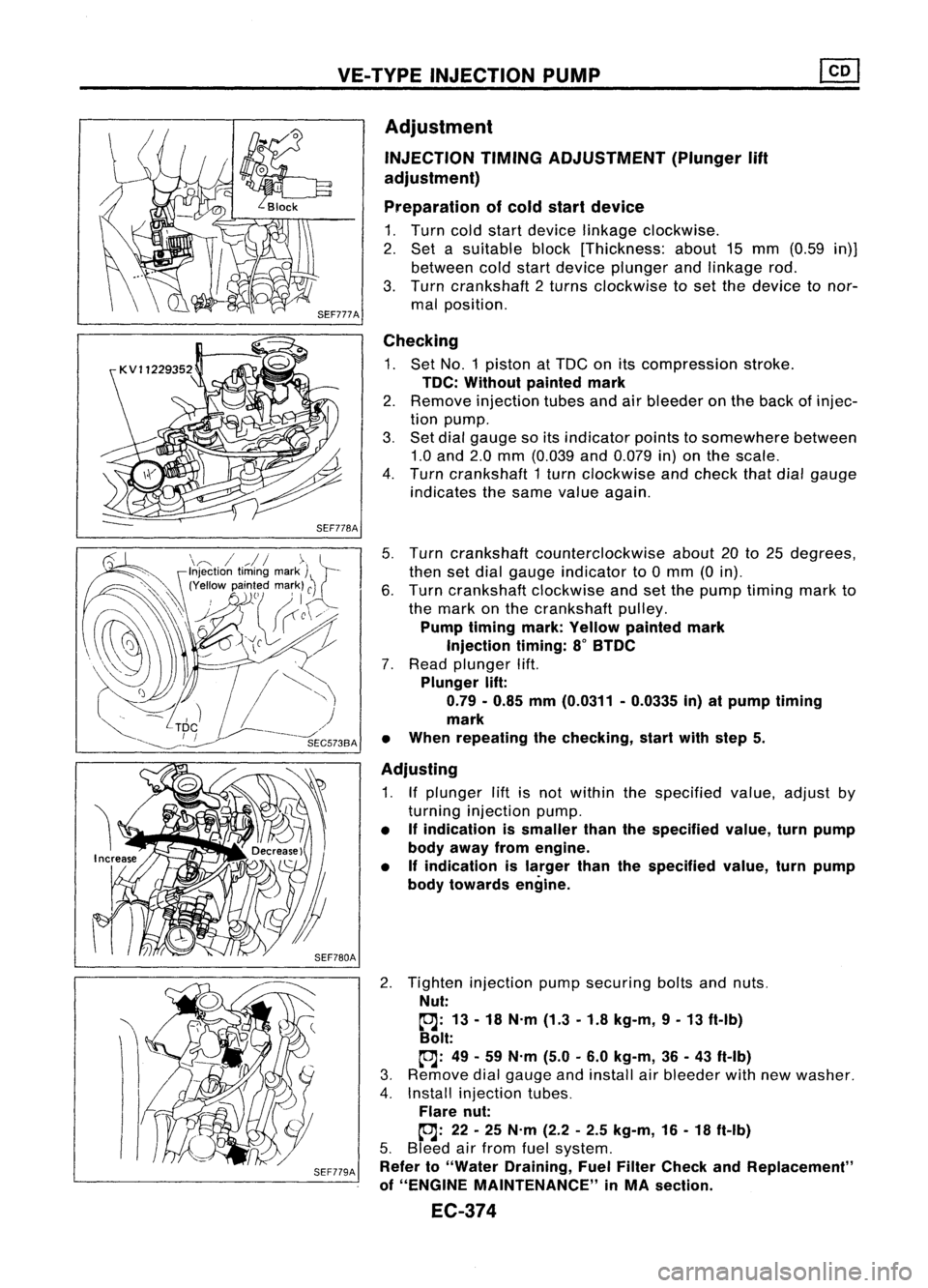
VE-TYPE INJECTION PUMP
SEF779A
Adjustment
INJECTION TIMINGADJUSTMENT (Plunger
lift
adjustment)
Preparation ofcold start device
1. Turn coldstart device linkage clockwise.
2. Set asuitable block[Thickness: about15mm (0.59 in)]
between coldstart device plunger andlinkage rod.
3. Turn crankshaft 2turns clockwise toset the device tonor-
mal position.
Checking
1. Set NO.1 piston atTDC onitscompression stroke.
TDC: Without paintedmark
2. Remove injection tubesandairbleeder onthe back ofinjec-
tion pump.
3. Set dial gauge soitsindicator pointstosomewhere between
1.0 and 2.0mm (0.039 and0.079 in)onthe scale.
4. Turn crankshaft 1turn clockwise andcheck thatdialgauge
indicates thesame value again.
5. Turn crankshaft counterclockwise about20to25 degrees,
then setdial gauge indicator to0mm (0in).
6. Turn crankshaft clockwiseandsetthe pump timing markto
the mark onthe crankshaft pulley.
Pump timing mark:Yellow painted mark
Injection timing:8
0
BTDC
7. Read plunger lift.
Plunger lift:
0.79 -0.85 mm(0.0311 -0.0335 in)atpump timing
mark
• When repeating thechecking, startwithstep 5.
Adjusting
1. Ifplunger liftisnot within thespecified value,adjust by
turning injection pump.
• Ifindication issmaller thanthespecified value,turnpump
body away fromengine.
• Ifindication islarger thanthespecified value,turnpump
body towards engine.
2. Tighten injection pumpsecuring boltsandnuts.
Nut:
~: 13-18 N.m (1.3-1.8 kg-m, 9-13 ft-Ib)
Bolt:
~: 49-59 N.m (5.0-6.0 kg-m, 36-43 ft-Ib)
3. Remove dialgauge andinstall airbleeder withnewwasher.
4. Install injection tubes.
Flare nut:
~: 22-25 N.m (2.2-2.5 kg-m, 16-18 ft-Ib)
5. Bleed airfrom fuelsystem.
Refer to"Water Draining, FuelFilter Check andReplacement"
of "ENGINE MAINTENANCE" inMA section.
EC-374
Page 1180 of 1701

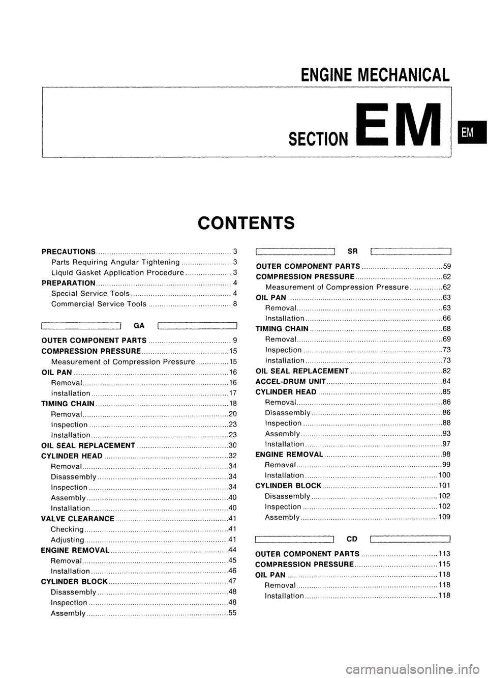
ENGINEMECHANICAL
SECTION
EM
CONTENTS
•
PRECAUTIONS
3
Parts Requiring AngularTightening 3
Liquid Gasket Application Procedure 3
PREPARATION 4
Special Service Tools 4
Commercial ServiceTools 8
GA
OUTER COMPONENT PARTS 9
COMPRESSION PRESSURE 15
Measurement ofCompression Pressure 15
OIL PAN 16
Removal 16
installation 17
TIMING CHAIN
18
Removal. 20
Inspection 23
Installation 23
OIL SEAL REPLACEMENT 30
CYLINDER HEAD 32
Removal 34
Disassembly 34
Inspection 34
Assembly 40
Installation 40
VALVE CLEARANCE 41
Checking 41
Adjusti ng 41
ENGINE REMOVAL .44
Removal 45
Ins taIIat ion " 46
CYLINDER BLOCK 47
Disassembly 48
Inspection 48
Assembly 55
SR
OUTER COMPONENT PARTS 59
COMPRESSION PRESSURE 62
Measurement ofCompression Pressure 62
OIL PAN
63
Removal 63
Installation ,66
TIMING CHAIN 68
Removal 69
Inspection 73
Installation ,73
OIL SEAL REPLACEMENT 82
ACCEL-DRUM UNIT 84
CYLINDER HEAD
85
Removal 86
Disassembly 86
Inspection 88
Assembly 93
Installation , 97
ENGINE REMOVAL 98
RemGval 99
Installation "100
CYLINDER BLOCK 101
Disassembly 102
Inspection , 102
Assembly 109
CD
OUTER COMPONENT PARTS
113
COMPRESSION PRESSURE 115
OIL PAN 118
Removal 118
Installation 118