1995 NISSAN ALMERA N15 flat tire
[x] Cancel search: flat tirePage 345 of 1701
Note
Note Clean sensor fixing
portion, orreplace sen-
sor.
NG
OK
OK
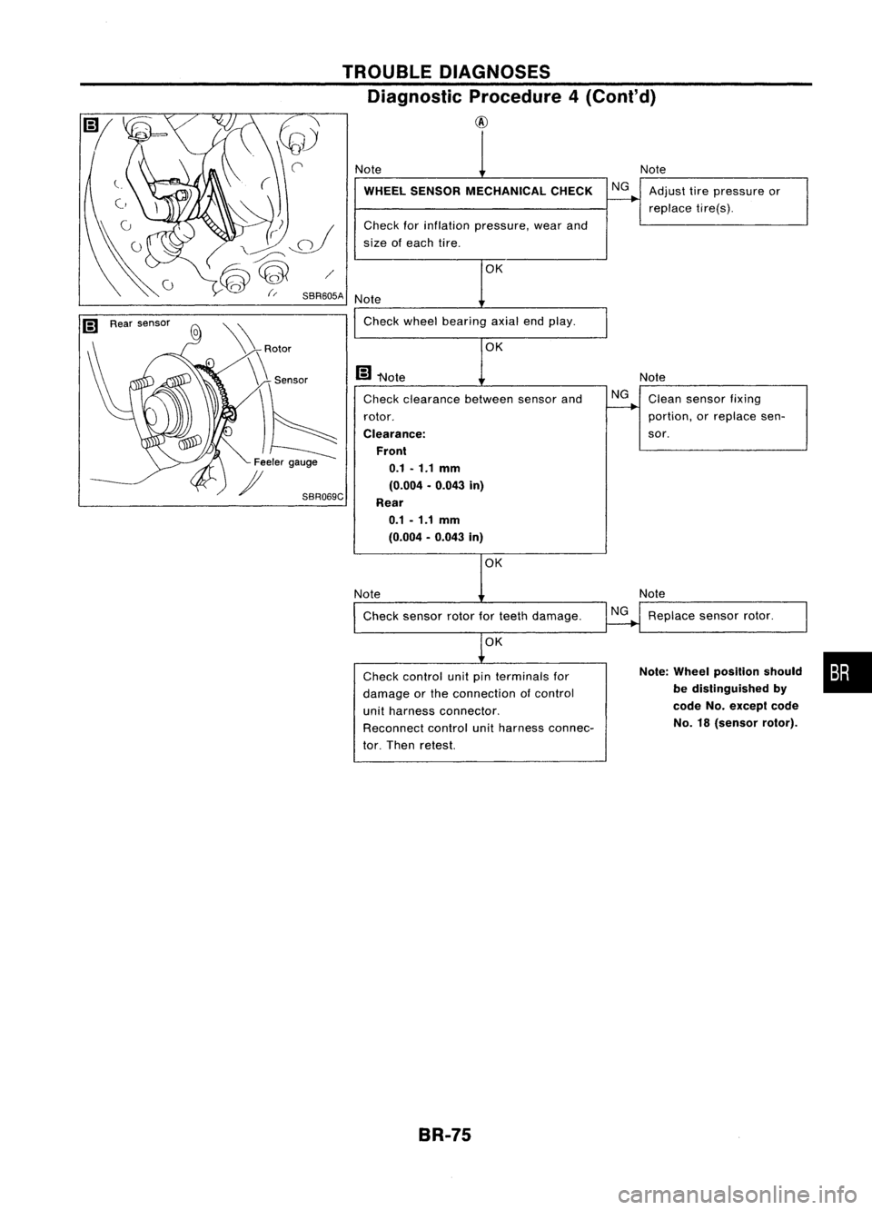
Check clearance betweensensorand
rotor.
Clearance: Front0.1 -1.1
mm
(0.004 .0.043 in)
Rear 0.1 -1.1 mm
(0.004 -0.043 in)
WHEEL
SENSOR MECHANICAL CHECK
NGAdjust tirepressure or
replace tire(s).
Check forinflation pressure, wearand
size ofeach tire.
Note
Note Check wheelbearing axialendplay.
m
"Note
TROUBLE
DIAGNOSES
Diagnostic Procedure4(Conl'd)
@
SBR069C
\
\ Rotor
\\ Sensor
)6
Feeler gauge
)I
OK
Note Check sensor rotorforteeth damage.
NG
Note
Replace sensorrotor.
OK
Check control unitpinterminals for
damage orthe connection ofcontrol
unit harness connector.
Reconnect controlunitharness connec-
tor. Then retest.
Note:
Wheel position should •••
be distinguished by
code
No.except code
No. 18(sensor rotor).
BR-75
Page 447 of 1701
Bulbcover
SEL995K HEADLAMP
Bulb Replacement
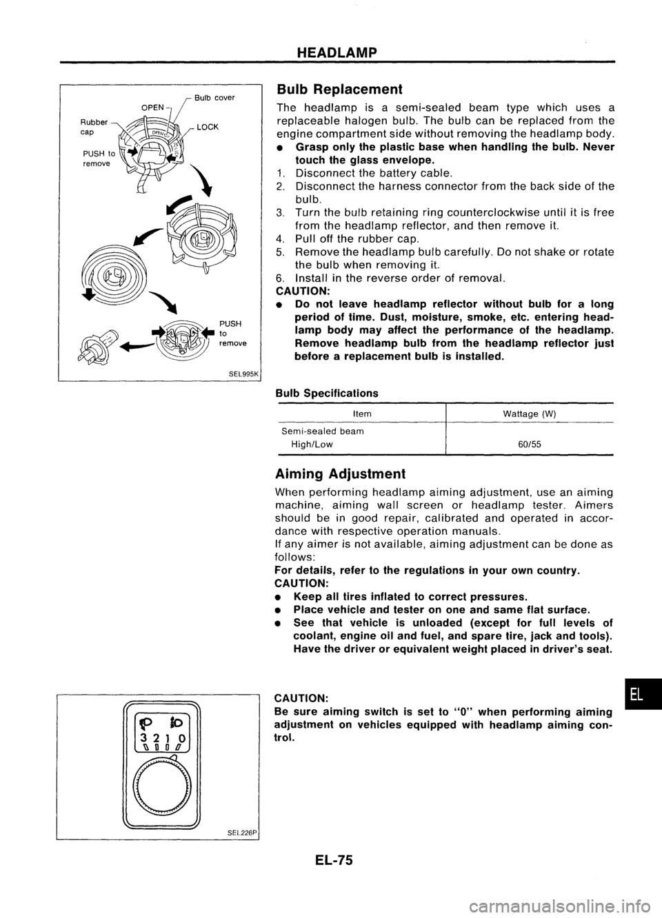
The headlamp isasemi-sealed beamtypewhich usesa
replaceable halogenbulb.Thebulb canbereplaced fromthe
engine compartment sidewithout removing theheadlamp body.
• Grasp onlytheplastic basewhen handling thebulb. Never
touch theglass envelope.
1. Disconnect thebattery cable.
2. Disconnect theharness connector fromtheback sideofthe
bulb.
3. Turn thebulb retaining ringcounterclockwise until
it
is free
from theheadlamp reflector,andthen remove it.
4. Pull offthe rubber cap.
5. Remove theheadlamp bulbcarefully. Donot shake orrotate
the bulb when removing it.
6. Install inthe reverse orderofremoval.
CAUTION:
• Do not leave headlamp reflector withoutbulbforalong
period oftime. Dust,moisture, smoke,etc.entering head-
lamp bodymayaffect theperformance ofthe head lamp.
Remove headlamp bulbfrom thehead lamp reflector just
before areplacement bulbisinstalled.
Bulb Specifications
Item
Semi-sealed beam
High/Low Wattage
(W)
60/55
f>
to
3 21 0
~ nOD
o
SEL226PAiming
Adjustment
When performing headlamp aiming adjustment, useanaiming
machine, aimingwallscreen orheadlamp tester.Aimers
should beingood repair, calibrated andoperated inaccor-
dance withrespective operationmanuals.
If any aimer isnot available, aimingadjustment canbedone as
follows:
For details, refertothe regulations inyour owncountry.
CAUTION:
• Keep alltires inflated tocorrect pressures.
• Place vehicle andtester onone and same flatsurface.
• See thatvehicle isunloaded (exceptforfull levels of
coolant, engineoiland fuel, andspare tire,jack andtools).
Have thedriver orequivalent weightplaced indriver's seat.
CAUTION: •
Be sure aiming switchisset to
"0"
when performing aiming
adjustment onvehicles equipped withheadlamp aiming con-
trol.
EL-75
Page 473 of 1701
GEL001EXTERIOR
LAMP
Front FogLamp BulbReplacement
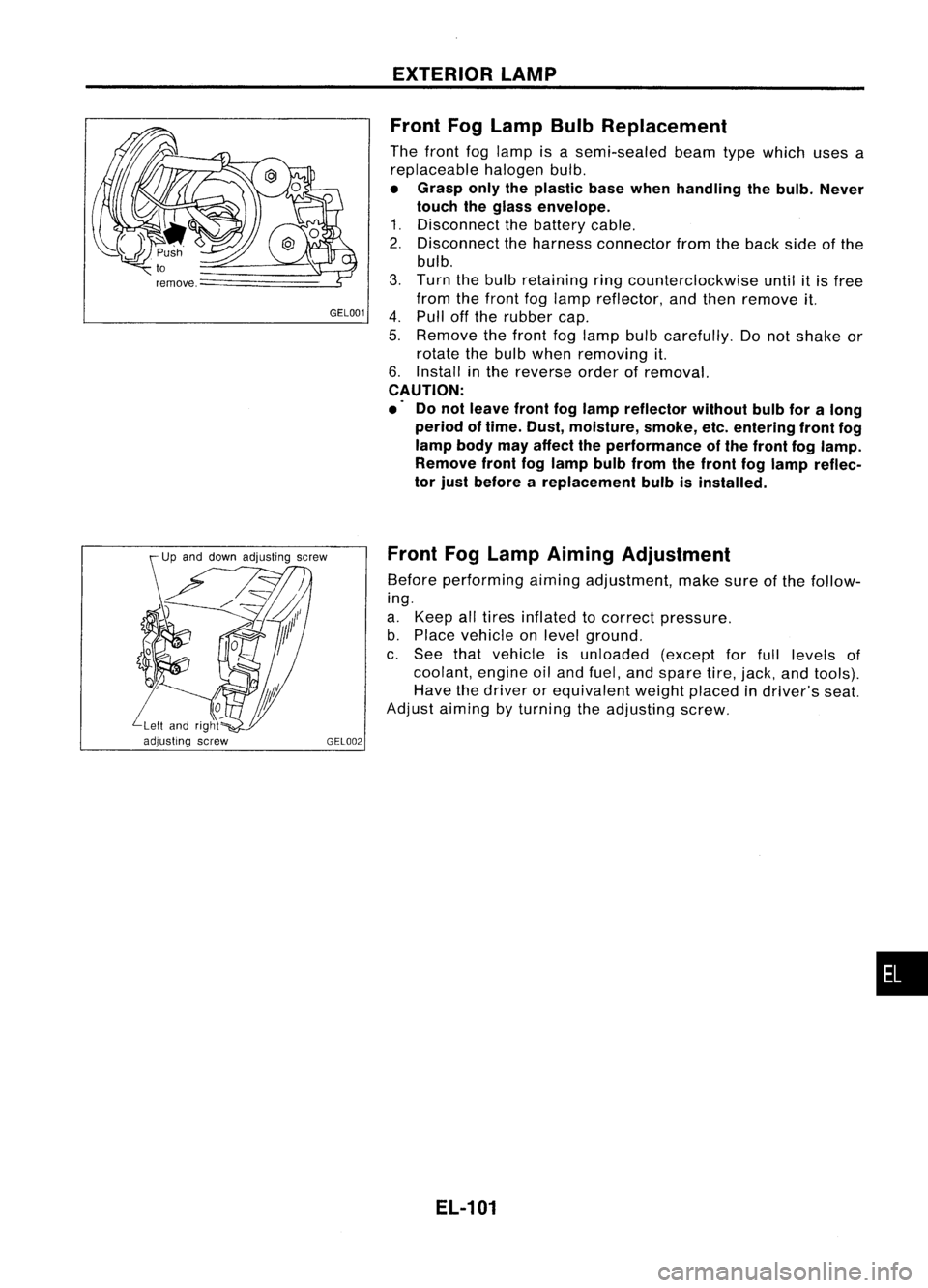
The front foglamp isasemi-sealed beamtypewhich usesa
replaceable halogenbulb.
• Grasp onlytheplastic basewhen handling thebulb. Never
touch theglass envelope.
1. Disconnect thebattery cable.
2. Disconnect theharness connector fromtheback sideofthe
bulb.
3. Turn thebulb retaining ringcounterclockwise untilitis free
from thefront foglamp reflector, andthen remove it.
4. Pull offthe rubber cap.
5. Remove thefront foglamp bulbcarefully. Donot shake or
rotate thebulb when removing it.
6. Install inthe reverse orderofremoval.
CAUTION:
.' Donot leave frontfoglamp reflector withoutbulbforalong
period oftime. Dust, moisture, smoke,etc.entering frontfog
lamp bodymayaffect theperformance ofthe front foglamp.
Remove frontfoglamp bulbfrom thefront foglamp reflec-
tor just before areplacement bulbisinstalled.
Front FogLamp Aiming Adjustment
Before performing aimingadjustment, makesureofthe follow-
ing.
a. Keep alltires inflated tocorrect pressure.
b. Place vehicle onlevel ground.
c. See thatvehicle isunloaded (exceptforfull levels of
coolant, engineoiland fuel, andspare tire,jack, andtools).
Have thedriver orequivalent weightplaced indriver's seat.
Adjust aiming byturning theadjusting screw.
EL-101
•
Page 688 of 1701
ON-VEHICLESERVICE
Front Wheel Alignment
Before checking frontwheel alignment, besure tomake apre-
liminary inspection (Unladen*).
*: Fuel, radiator coolantandengine oilfull. Spare tire,jack,
hand tools andmats indesignated positions.
SFA575B PRELIMINARY INSPECTION
1. Check tiresforwear andimproper inflation.
2. Check wheelrunout.
Wheel runout:
Refer toSOS (FA-30).
3. Check frontwheel bearings forlooseness.
4. Check frontsuspension forlooseness.
5. Check steering linkageforlooseness.
6. Check thatstruts workproperly.
7. Check vehicle posture (Unladen).
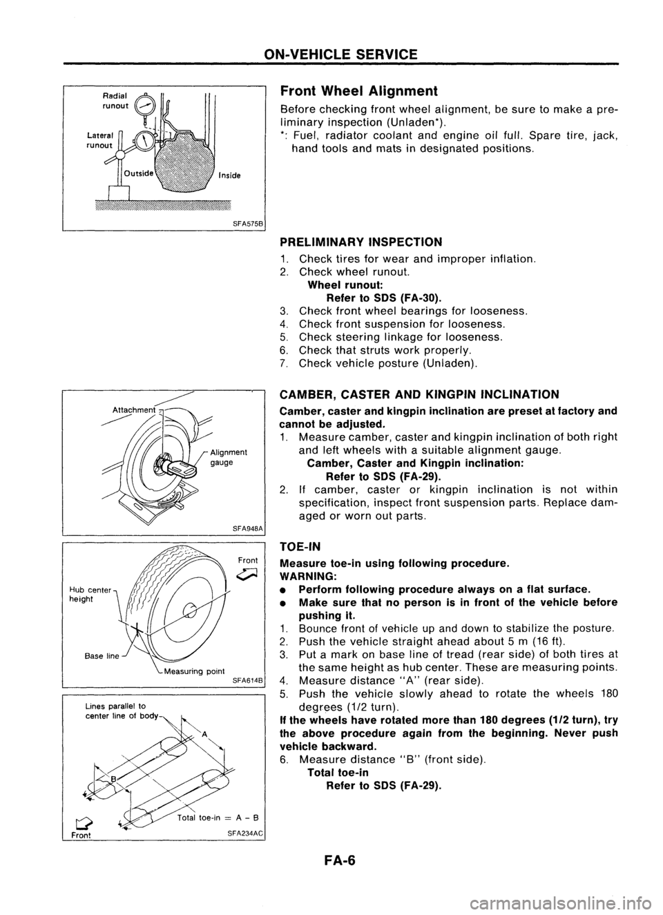
TOE-IN Measure toe-inusingfollowing procedure.
WARNING:
• Perform following procedure alwaysonaflat surface.
• Make surethatnoperson isin front ofthe vehicle before
pushing it.
1. Bounce frontofvehicle upand down tostabilize theposture.
2. Push thevehicle straight aheadabout5m (16 ft).
3. Put amark onbase lineoftread (rearside) ofboth tires at
the same height ashub center. Thesearemeasuring points.
4. Measure distance"A"(rear side).
5. Push thevehicle slowlyaheadtorotate thewheels 180
degrees (1/2turn).
If the wheels haverotated morethan180degrees
(112
turn), try
the above procedure againfromthebeginning. Neverpush
vehicle backward.
6. Measure distance"B"(front side).
Total toe-in
Refer toSOS (FA-29).
CAMBER,
CASTERANDKINGPIN INCLINATION
Camber, casterandkingpin inclination arepreset atfactory and
cannot beadjusted.
1. Measure camber,casterandkingpin inclination ofboth right
and leftwheels withasuitable alignment gauge.
Camber, CasterandKingpin inclination:
Refer toSOS (FA-29).
2. Ifcamber, casterorkingpin inclination isnot within
specification, inspectfrontsuspension parts.Replace dam-
aged orworn outparts.
Front
SFA948A
SFA614B
SFA234AC
Lines
parallel to
center lineofbody
Q
Front
Hub
center
height
FA-6
Page 1224 of 1701
ENGINEREMOVAL
WARNING:
a. Situate vehicle onaflat and solid surface.
b. Place chocks atfront andback ofrear wheels.
c. Donot remove engineuntilexhaust systemhascompletely
cooled off.
Otherwise, youmay burn yourself and/orfiremay break out
in fuel line.
d. For safety during subsequent steps,thetension ofwires
should beslackened againsttheengine.
e. Before disconnecting fuelhose, release fuelpressure from
fuel line.
Refer to"Releasing FuelPressure" inEC section.
f. Besure tohoist engine andtransaxle inasafe manner.
g. For engines notequipped withengine slingers, attach
proper slingers andbolts described inPARTS CATALOG.
CAUTION:
• When liftingengine, besure toclear surrounding parts.
Take special careforaccelerator wirecasing, brakelines
and brake master cylinder.
• Inhoisting theengine, alwaysuseengine slingers inasafe
manner.
• Inremoving driveshaft, becareful nottodamage grease
seal oftransaxle.
Engine cannotberemoved separately fromtransaxle. Remove
engine withtransaxle.
Removal
1. Drain water.
2. Remove hood.
3. Remove battery.
4. Remove reservoir tankandbracket.
5. Remove drivebelts.
6. Remove alternator, compressor andpower steering oil
pump fromengine.
Power steering pumpdoesnotneed tobe disconnected from
power steering tubes.
7. Remove thefollowing parts:
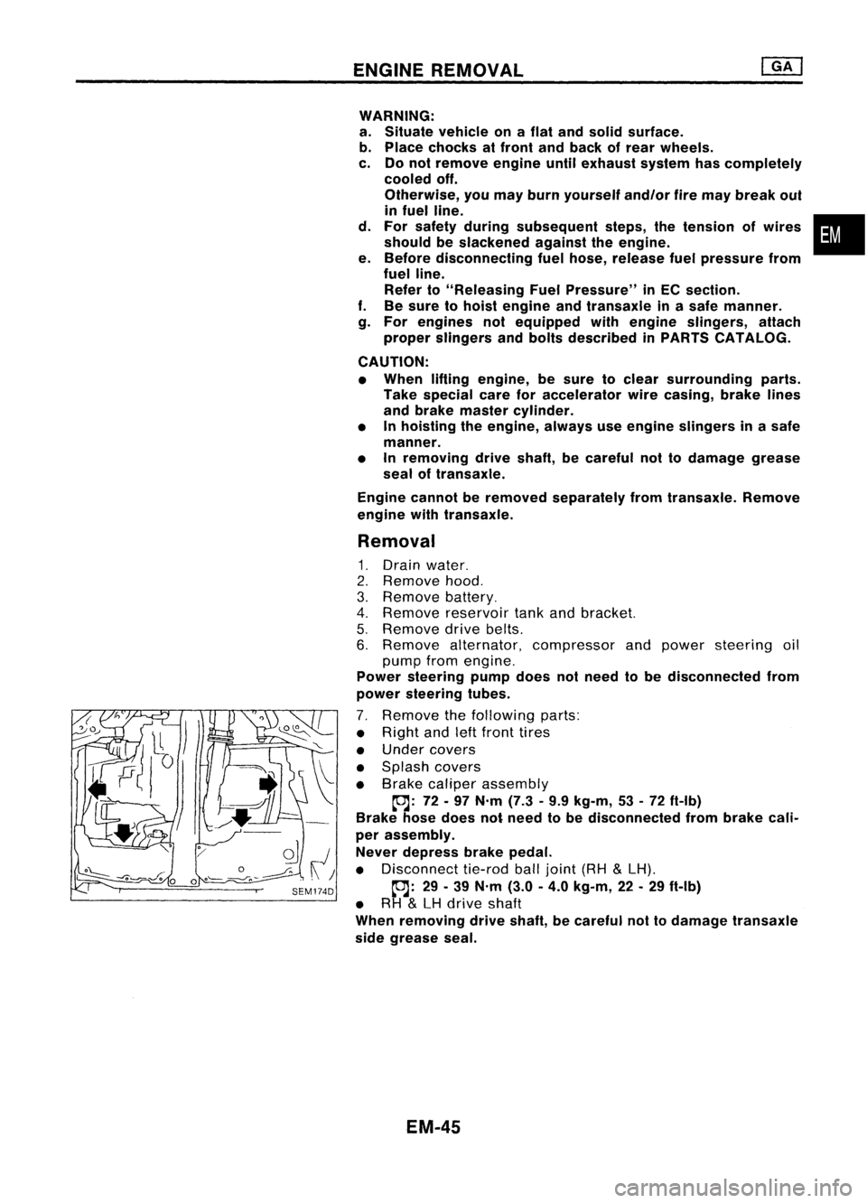
• Right andleftfront tires
• Under covers
• Splash covers
• Brake caliper assembly
~: 72-97 N'm (7.3•9.9 kg-m, 53•72 ft-Ib)
Brake hosedoes notneed tobe disconnected frombrake cali-
per assembly.
Never depress brakepedal.
• Disconnect tie-rodballjoint (RH
&
LH).
~: 29-39 N'm (3.0-4.0 kg-m, 22-29 ft-Ib)
• RH
&
LH drive shaft
When removing driveshaft, becareful nottodamage transaxle
side grease seal.
EM-45
•
Page 1613 of 1701
ON-VEHICLESERVICE
Rear Wheel Alignment
PRELIMINARY INSPECTION
Make following checks.Adjust,repairorreplace ifnecessary.
• Check tiresforwear andforimproper inflation.
• Check rearwheel bearings forexcessive play.
• Check wheelrunout.
Wheel runout: RefertoSOS inFA section.
• Check thatrear shock absorber worksproperly.
• Check rearaxleandrear suspension partsforexcessive
SFA575B
play.
• Check vehicle posture (Unladen*).
*: Fuel, radiator andengine oilfull. Spare tire,jack, hand
tools andmats indesignated positions.
•
CAMBER
Camber ispreset atfactory andcannot beadjusted.
Camber: Refer toSOS (RA-12).
• Ifthe camber isnot within specification, inspectandreplace
any damaged orworn rearsuspension parts.
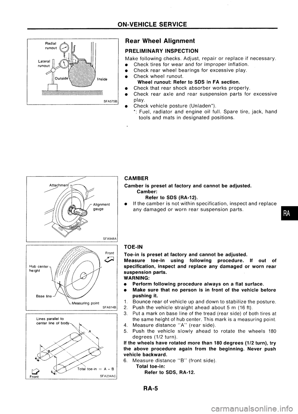
TOE-IN
Toe-in ispreset atfactory andcannot beadjusted.
Measure toe-inusingfollowing procedure. Ifout of
specification, inspectandreplace anydamaged orworn rear
suspension parts.
WARNING:
• Perform following procedure alwaysonaflat surface.
• Make surethatnoperson isin front ofthe vehicle before
pushing it.
1. Bounce rearofvehicle upand down tostabilize theposture.
2. Push thevehicle straight aheadabout5m (16
ft).
3. Putamark onbase lineofthe tread (rearside) ofboth tires at
the same height ofhub center. Thismark isameasuring point.
4. Measure distance"A"(rear side).
5. Push thevehicle slowlyaheadtorotate thewheels 180
degrees (1/2turn).
If the wheels haverotated morethan180degrees (1/2turn), try
the above procedure againfromthebeginning. Neverpush
vehicle backward.
6. Measure distance"B"(front side).
Total toe-in:
Refer toSOS, RA-12.
Front
SFA948A
SFA614B
SFA234AC
Lines
parallel to
center lineofbOdY~
Q
Front
Hub
center
height
RA-5
Page 1628 of 1701
SUPPLEMENTALRESTRAINTSYSTEM(SRS)
Precautions forSRS "AirBag" and"Seat Belt
Pre-tensioner" Service
• Donot use acircuit testertocheck SRScircuits.
• Before servicing theSRS. turnignition switch"OFF", disconnect bothbattery cablesandwait forat
least 10minutes.
For approximately 10minutes afterthecables areremoved, itis still possible forthe airbag to
deploy. Therefore, donot work onany SRS connectors orwires untilatleast 10minutes havepassed.
• For single airbag system, donot separate diagnosis sensorunitfrom steering wheel.
• For dual airbag system. diagnosis sensorunitmust always beinstalled withtheir arrow marks
"Q"
pointing towards thefront ofthe vehicle forproper operation. Alsocheck diagnosis sensorunitfor
cracks. deformities orrust before installation andreplace asrequired.
• The spiral cablemustbealigned withtheneutral position sinceitsrotations arelimited. Donot
attempt toturn steering wheelorcolumn afterremoval ofsteering gear.
• Handle airbag module carefully. Alwaysplaceitwith thepad side facing upward.
• Donot use oldbolts afterremoving anySRS parts; replace withnewones. Conduct self-diagnosis
to check entire SRSforproper function.
• For dual airbag system, instrument panelassembly shouldbereplaced afterairbag inflates.
X
X
Use
forspecial bolts
[TAMPER RESISTANT
TORX (SizeT50))
a:
3.5 (0.138)
dia.
b: 8.5 -8.6
(0.335 •0.339) dia.
c: approx.
10
(0.39) sq.
c
NT354
a
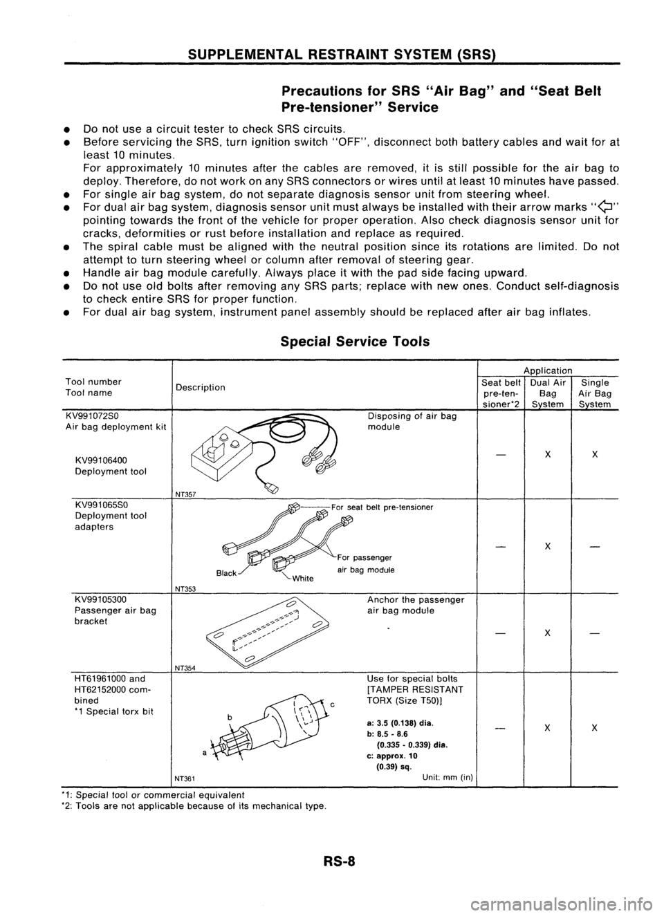
HT61961000
and
HT62152000 com-
bined *1 Special torxbit
Special
Service Tools
Application
Tool number
Description Seat
belt DualAir Single
Tool name
pre-ten-BagAirBag
sioner*2 Sstem Sstem
KV991072So Disposingofair bag
Air bag deployment kit module
KV991 06400
X
X
Deployment tool
KV991065So
Deployment tool
adapters
X
For passenger
air bag module
NT353
KV991 05300 Anchorthepassenger
Passenger airbag
airbag module
bracket
X
NT361
Unit:
mm(in)
*1: Special toolorcommercial equivalent
*2: Tools arenotapplicable becauseofits mechanical type.
RS-8
Page 1660 of 1701
COLLISIONDIAGNOSIS -Dual AirBag System
To repair theSRS, perform thefollowing steps.
When SRSisactivated inacollision:
CD
Replace thediagnosis sensorunit.
@ Remove
theairbag modules.
@
Check theSRS components usingthetable shown below:
• Replace anySRS components showing
visible
signsofdamage (dents,cracks, deformation).
@
Conduct self-diagnosis. Referto"Self-diagnosis" fordetails (RS-32). Ensuretheremainder ofthe
SRS isoperating properly.
@
Conduct self-diagnosis again.
When SRSisnot activated inacollision:
CD
Check theSRS components usingthetable shown below:
• Replace anySRS components showingvisiblesignsofdamage (dents,cracks, deformation).
@
Conduct self-diagnosis usingCONSULT and"'AIR BAG" warning lamp.Referto"Self-diagnosis" for
details (RS-32). EnsureentireSRSoperates properly.
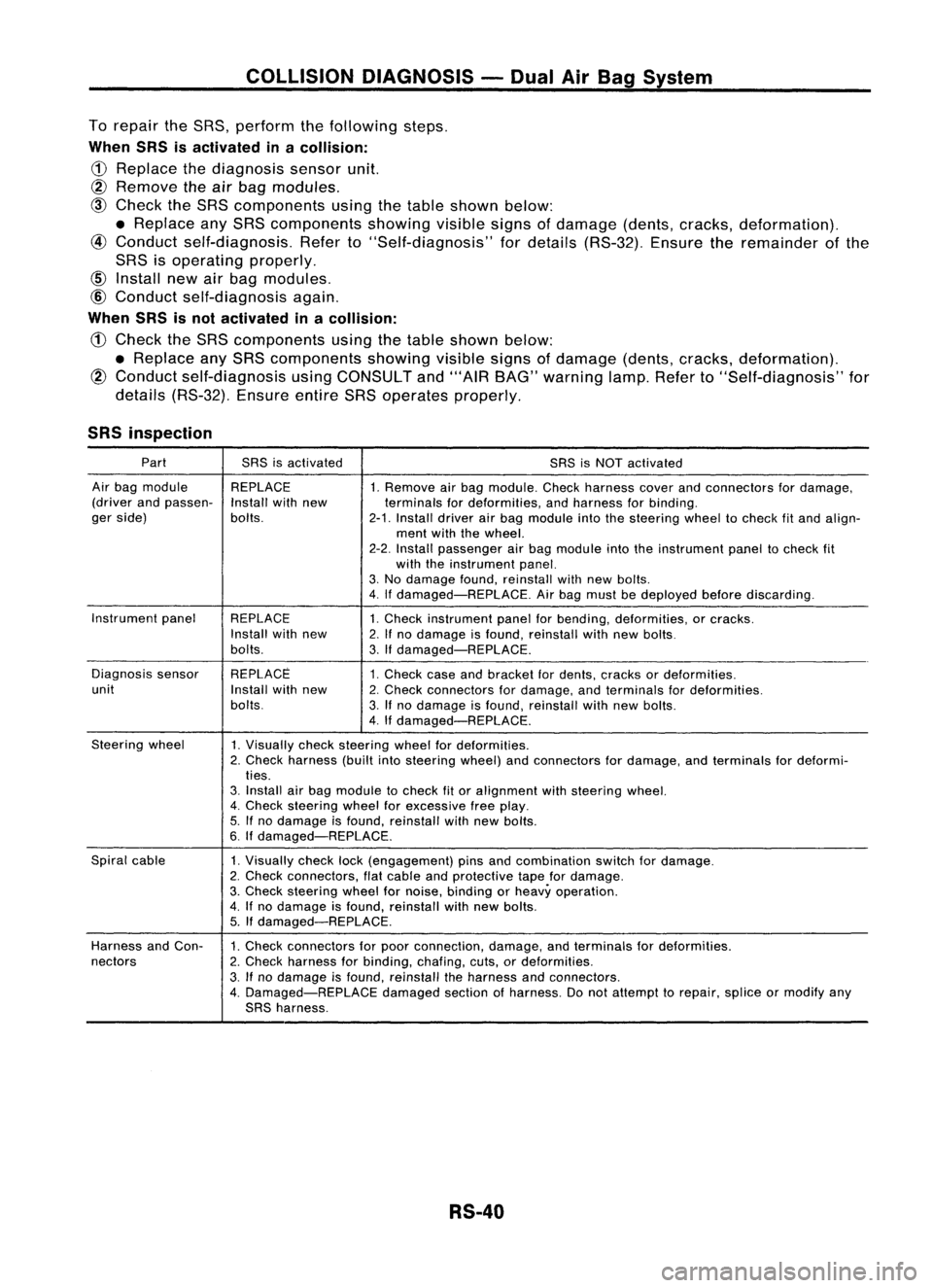
SRS inspection
Part SRSisactivated
SRSisNOT activated
Air bag module REPLACE
1.Remove airbag module. Checkharness coverandconnectors fordamage,
(driver andpassen-
Installwithnew terminalsfordeformities, andharness forbinding.
ger side) bolts.
2-1.Install driverairbag module intothesteering wheeltocheck fitand align-
ment withthewheel.
2-2. Install passenger airbag module intotheinstrument paneltocheck fit
with theinstrument panel.
3. No damage found,reinstall withnewbolts.
4. Ifdamaged-REPLACE. Airbag must bedeployed beforediscarding.
Instrument panel
REPLACE 1.Check instrument panelforbending, deformities, orcracks.
Install withnew
2.Ifno damage isfound, reinstall withnewbolts.
bolts. 3.Ifdamaged-REPLACE.
Diagnosis sensor REPLACE
1.Check caseandbracket fordents, cracks ordeformities.
unit Installwithnew
2.Check connectors fordamage, andterminals fordeformities.
bolts. 3.Ifno damage isfound, reinstall withnewbolts.
4. Ifdamaged-REPLACE.
Steering wheel
1.Visually checksteering wheelfordeformities.
2. Check harness (builtintosteering wheel)andconnectors fordamage, andterminals fordeformi-
ties.
3. Install airbag module tocheck fitor alignment withsteering wheel.
4. Check steering wheelforexcessive freeplay.
5. Ifno damage isfound, reinstall withnewbolts.
6. Ifdamaged-REPLACE.
Spiral cable
1.Visually checklock(engagement) pinsandcombination switchfordamage.
2. Check connectors, flatcable andprotective tapefordamage.
3. Check steering wheelfornoise, binding orheavy operation.
4. Ifno damage isfound, reinstall withnew bolts.
5. Ifdamaged-REPLACE.
Harness andCon-
1.Check connectors forpoor connection, damage,andterminals fordeformities.
nectors 2.Check harness forbinding, chafing,cuts,ordeformities.
3. Ifno damage isfound, reinstall theharness andconnectors.
4. Damaged-REPLACE damagedsectionofharness. Donot attempt torepair, spliceormodify any
SRS harness.
RS-40