1995 NISSAN ALMERA N15 how to read wiring
[x] Cancel search: how to read wiringPage 2 of 1701
CONTENTS(Cont'd.)
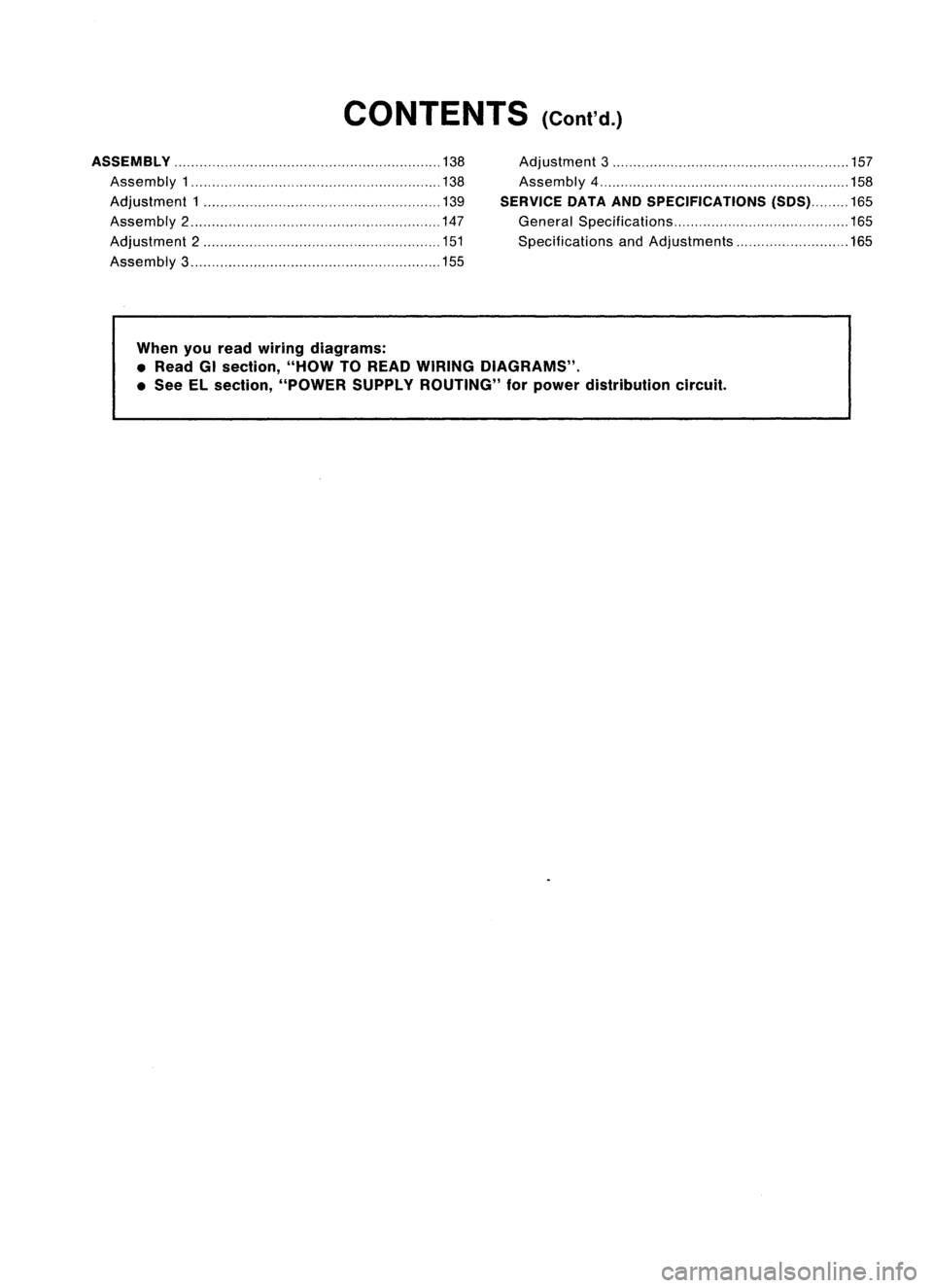
ASSEMBLy 138
Assembly
1 138
Adjustment
1 139
Assembly 2 147
Adjustment
2 151
Assembly
3 155
Adjustment
3 157
Assembly
4 158
SERVICE DATAANDSPECIFICATIONS (SOS)165
General Specifications
165
Specifications andAdjustments 165
When youread wiring diagrams:
• Read GIsection, "HOWTOREAD WIRING DIAGRAMS" .
• See ELsection, "POWER SUPPLYROUTING" forpower distribution circuit.
Page 272 of 1701
CONTENTS
(Cont'd.)
When youread wiring diagrams:
• Read GIsection, "HOWTOREAD WIRING DIAGRAMS" .
• See Elsection, "POWER SUPPLYROUTING" forpower distribution circuit.
When youperform troublediagnoses, readGIsection, "HOWTOFOllOW FLOWCHART
IN TROUBLE DIAGNOSES" and"HOW TOPERFORM EFFICIENT DIAGNOSIS FORAN
ELECTRICAL INCIDENT".
Page 373 of 1701

ELECTRICALSYSTEM
SECTION
EL
When youread wiring diagrams:
• Read GIsection, "HOWTOREAD WIRING DIAGRAMS".
When youperform troublediagnos.es, readGIsection, "HOWTOFOllOW FLOWCHART
IN TROUBLE DIAGNOSES" and"HOW TOPERFORM EFFICIENT DIAGNOSIS FORAN
ELECTRICAL INCIDENT".
CONTENTS
PRECAUTIONS 4
Supplemental RestraintSystem(SRS)"AIR
BAG" (DualAirBag System) 4
Supplemental RestraintSystem(SRS)"AIR
BAG" (Single AirBag System) 4
HARNESS CONNECTOR 5
Description 5
STANDARDIZED RELAy 6
Description 6
POWER SUPPLY ROUTING 8
Schematic 8
Wiring Diagram -POWER - 10
Fuse 19
Fusible Link 19
Circuit Breaker 19
GROUND DISTRIBUTION 20
BATTERy 25
How toHandle Battery 25
Battery TestandCharging Chart.. 28
Service DataandSpecifications (SOS) 32
STARTING SySTEM
33
Wiring Diagram -START - 33
Trouble Diagnoses 35
Construction 36
Removal andInstallation .45
Magnetic SwitchCheck .46
Pinion/Clutch Check 46
Brush Check 46
Yoke Check 47
Armature Check 48
Assembly .49
Service DataandSpecifications (SDS) 50
CHARGING SYSTEM 52
Wiring Diagram -CHARGE - 52
Trouble Diagnoses 54Construction
55
Removal andInstallation 57
Disassembly 57
Rotor Check 57
Brush Check 58
Stator Check 58
Diode Check 59
Assembly 60
Service DataandSpecifications (SDS) 61
COMBINATION SWITCH 62
Combination Switch/Check 62
Replacement 64
HEADLAMP -Without Daytime lightSystem -65
Wiring Diagram -H/LAMP - 65
Trouble Diagnoses 67
HEADLAMP -Daytime lightSystem - 68
Operation (Daytimelightsystem) 68
System Description 69
Schematic 70
Wiring Diagram -DTRL - 71
Trouble Diagnoses (DaytimeLight) 74
HEADLAMP 75
Bulb Replacement... 75•
Aiming Adjustment. 75
HEADLAMP -Headlamp Aiming
Control- 77
Wiring Diagram -AIM - 77
Description 81
EXTERIOR LAMP 82
Clearance, LicenseandTail Lamps/Schematic 82
Clearance, LicenseandTail Lamps/Wiring
Diagram -TAILIL - 83
Stop Lamp/Wiring Diagram-STOP/L - 92
Back-up Lamp/Wiring Diagram-BACK/L -94
Front FogLamp/Wiring Diagram-F/FOG -96
Front FogLamp BulbReplacement 101
Page 375 of 1701
CONTENTS(Cont'd.)
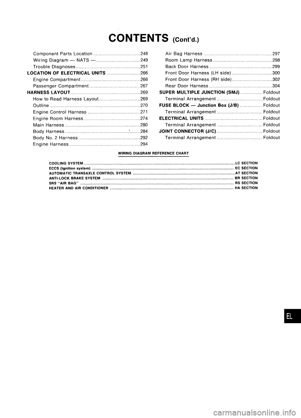
Component PartsLocation 248
Wiring Diagram -NATS - 249
Trouble Diagnoses 251
LOCATION OFELECTRICAL UNITS
266
Engine Compartment 266
Passenger Compartment 267
HARNESS LAyOUT
269
How toRead Harness Layout... 269
Outline 270
Engine Control Harness 271
Engine RoomHarness 274
Main Harness '" 280
Body Harness :284
Body No.2 Harness 292
Engine Harness 294Air
Bag Harness 297
Room LampHarness 298
Back DoorHarness 299
Front DoorHarness (LHside) 300
Front DoorHarness (RHside) 302
Rear Door Harness 304
SUPER MULTIPLE JUNCTION
(SMJ) Foldout
Terminal Arrangement Foldout
FUSE BLOCK -Junction Box
(JIB)
Foldout
Terminal Arrangement Foldout
ELECTRICAL UNITS
Foldout
Terminal Arrangement Foldout
JOINT CONNECTOR
(J/C)
Foldout
Terminal Arrangement Foldout
WIRING DIAGRAM REFERENCE CHART
COOLING SYSTEM
LC
SECTION
ECCS (Ignition syslem) ECSECTION
AUTOMATIC TRANSAXLECONTROLSYSTEM ATSECTION
ANTI-LOCK BRAKESYSTEM BRSECTION
SRS "AIR BAG" RSSECTION
HEATER ANDAIRCONDITIONER HASECTION
•
Page 722 of 1701
CONTENTS(Cont'd.)
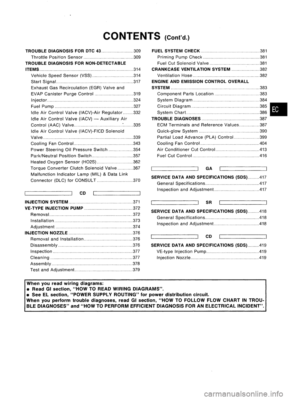
TROUBLE DIAGNOSIS FORDTC
43 309
Throttle Position Sensor 309
TROUBLE DIAGNOSIS FORNON-DETECTABLE
ITEMS
314
Vehicle SpeedSensor (VSS) 314
Start Signal 317
Exhaust GasRecirculation (EGR)Valveand
EVAP Canister PurgeControl 319
Injector 324
Fuel Pump 327
Idle AirControl Valve(IACV)-Air Regulator 332
Idle AirControl Valve(IACV) -Auxiliary Air
Control (AAC)Valve :335
Idle AirControl Valve(IACV)-FICD Solenoid
Valve '"339
Cooling FanControl 343
Power Steering OilPressure Switch 354
Park/Neutral PositionSwitch 357
Heated Oxygen Sensor(H02S) 362
Torque
Converter
ClutchSolenoid Valve 367
Malfunction IndicatorLamp(MIL)
&
Data Link
Connector (DLC)forCONSULT 370
CD
INJECTION SYSTEM
371
VE.TYPE INJECTION PUMP
372
Removal 372
Installation 373
Adjustment 374
INJECTION NOZZLE
376
Removal andInstallation 376
Disassembly 376
Inspection 377
Cleaning 377
Assembly 378
Test andAdjustment 379
FUEL
SYSTEM CHECK
381
Priming PumpCheck 381
Fuel CutSolenoid Valve 381
CRANKCASE VENTILATION SYSTEM
382
Ventilation Hose 382
ENGINE ANDEMISSION CONTROLOVERALL
SYSTEM
383
Component PartsLocation 383
System Diagram 384
Circuit Diagram ,385
System Chart. 386
TROUBLE DIAGNOSES
387
ECM Terminals andReference Values 387
Quick-glow System 390
Partial LoadAdvance (PLA)Control 399
Cooling FanControl 404
Air Conditioner CutControl 413
Fuel CutControl 416
GA
SERVICE DATAANDSPECIFICATIONS
(505).417
General Specifications 417
Inspection andAdjustment.. 417
SR
SERVICE DATAANDSPECIFICATIONS
(505).418
General Specifications 418
Inspection andAdjustment.. .418
CD
SERVICE DATAANDSPECIFICATIONS
(505).419
VE-type Injection Pump 419
Injection Nozzle 419
•
When youread wiring diagrams:
• Read GIsection, "HOWTOREAD WIRING DIAGRAMS" .
• See Elsection, "POWER SUPPLYROUTING" forpower distribution circuit.
When youperform troublediagnoses, readGIsection, "HOWTOFOllOW FLOWCHART INTROU-
BLE DIAGNOSES" and"HOW TOPERFORM EFFICIENT DIAGNOSIS FORANELECTRICAL INCIDENT".
Page 779 of 1701
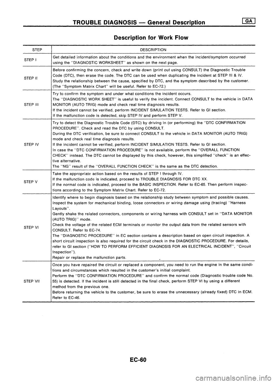
STEP
STEP I
STEP II
STEP III
STEP IV
STEP V
STEP VI
STEP VII
TROUBLE
DIAGNOSIS -General oescrip_ti_on
I_G_A_'
Description forWork Flow
DESCRIPTION
Get detailed information abouttheconditions andtheenvironment whentheincident/symptom occurred
using the"DIAGNOSTIC WORKSHEET" asshown onthe next page.
Before confirming theconcern, checkandwrite down (printoutusing CONSULT) theDiagnostic Trouble
Code (DTC), thenerase thecode. TheDTC canbeused when duplicating theincident atSTEP III
&
IV.
Study therelationship betweenthecause, specified byDTC, andthesymptom described bythe customer.
(The "Symptom MatrixChart" willbeuseful. RefertoEC-72.)
Try toconfirm thesymptom andunder whatconditions theincident occurs.
The "DIAGNOSTIC WORKSHEET" isuseful toverify theincident. ConnectCONSULT tothe vehicle inDATA
MONITOR (AUTOTRIG)modeandcheck realtime diagnosis results.
If the incident cannotbeverified, performINCIDENT SIMULATION TESTS.RefertoGI section.
If the malfunction codeisdetected, skipSTEP IVand perform STEPV.
Try todetect theDiagnostic TroubleCode(DTC) bydriving in(or performing) the"DTC CONFIRMATION
PROCEDURE". Checkandread theDTC byusing CONSULT.
During theDTC verification, besure toconnect CONSULT tothe vehicle inDATA MONITOR (AUTOTRIG)
mode andcheck realtime diagnosis results.
If
the incident cannotbeverified, performINCIDENT SIMULATION TESTS.RefertoGI section.
In case the"DTC CONFIRMATION PROCEDURE"isnot available, performthe"OVERALL FUNCTION
CHECK" instead.TheDTC cannot bedisplayed bythis check, however, thissimplified "check"isan effec-
tive alternative.
The "NG" result ofthe "OVERALL FUNCTIONCHECK"isthe same asthe DTC detection.
Take theappropriate actionbasedonthe results ofSTEP Ithrough IV.
If the malfunction codeisindicated, proceedtoTROUBLE DIAGNOSIS FORDTCXX.
If the normal codeisindicated, proceedtothe BASIC INSPECTION. RefertoEC-65. Thenperform inspec-
tions according tothe Symptom MatrixChart.RefertoEC-72.
Identify wheretobegin diagnosis basedonthe relationship studybetween symptom andpossible causes.
Inspect thesystem formechanical binding,looseconnectors orwiring damage using(tracing) "Harness
Layouts".
Gently shaketherelated connectors, components orwiring harness withCONSULT setin"DATA MONITOR
(AUTO TRIG)" mode.
Check thevoltage ofthe related ECMterminals ormonitor theoutput datafrom therelated sensors with
CONSULT. RefertoEC-74.
The "DIAGNOSTIC PROCEDURE" inEC section contains adescription basedonopen circuit inspection. A
short circuit inspection isalso required forthe circuit checkinthe DIAGNOSTIC PROCEDURE. Fordetails,
refer toGI section ("HOWTOPERFORM EFFICIENT DIAGNOSIS FORANELECTRICAL INCIDENT","Circuit
Inspection' ').
Repair orreplace themalfunction parts.
Once youhave repaired thecircuit orreplaced acomponent, youneed torun theengine inthe same condi-
tions andcircumstances whichresulted inthe customer's initialcomplaint.
Perform the"DTC CONFIRMATION PROCEDURE"andconfirm thenormal code(Diagnostic troublecodeNo.
55) isdetected. Ifthe incident isstill detected inthe final check, perform STEPVIby using adifferent
method fromtheprevious one.
Before returning thevehicle tothe customer, besure toerase theunnecessary (alreadyfixed)DTCinECM.
Refer toEC-46.
EC-60
Page 985 of 1701
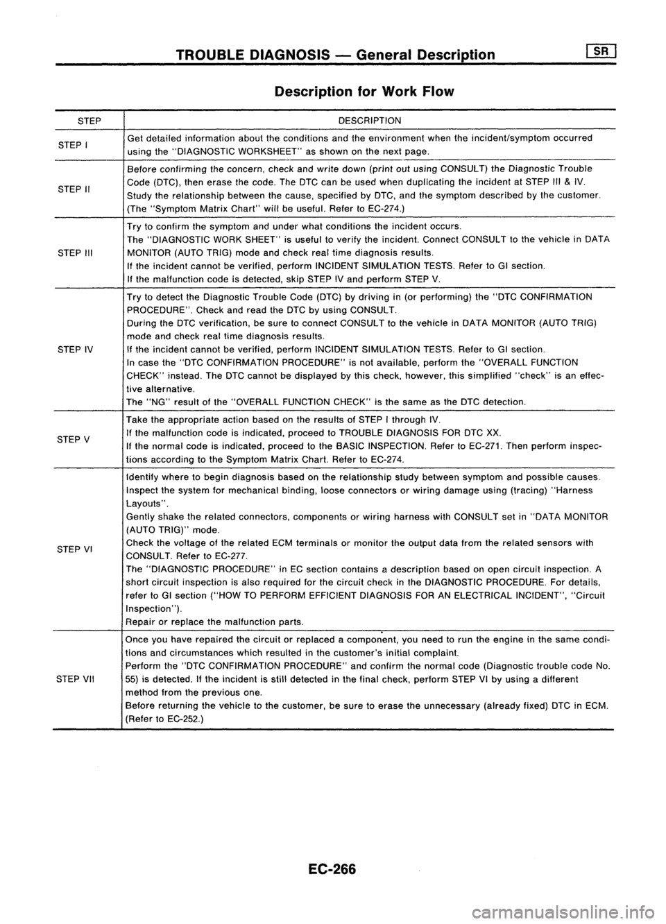
STEP
STEP I
STEP II
STEP III
STEP IV
STEP V
STEP VI
STEP VII
TROUBLE
DIAGNOSIS -General Description
Description forWork Flow
DESCRIPTION
Get detailed information abouttheconditions andtheenvironment whentheincident/symptom occurred
using the"DIAGNOSTIC WORKSHEET" asshown onthe next page.
Before confirming theconcern, checkandwrite down (printoutusing CONSULT) theDiagnostic Trouble
Code (DTC), thenerase thecode. TheDTC canbeused when duplicating theincident atSTEP
1/1
&
IV.
Study therelationship betweenthecause, specified byDTC, andthesymptom described bythe customer.
(The "Symptom MatrixChart" willbeuseful. RefertoEC-274.)
Try toconfirm thesymptom andunder whatconditions theincident occurs.
The "DIAGNOSTIC WORKSHEET" isuseful toverify theincident. ConnectCONSULT tothe vehicle inDATA
MONITOR (AUTOTRIG)modeandcheck realtime diagnosis results.
If the incident cannotbeverified, performINCIDENT SIMULATION TESTS.RefertoGI section.
If the malfunction codeisdetected, skipSTEP IVand perform STEPV.
Try todetect theDiagnostic TroubleCode(DTC) bydriving in(or performing) the"DTC CONFIRMATION
PROCEDURE". Checkandread theDTC byusing CONSULT.
During theDTC verification, besure toconnect CONSULT tothe vehicle inDATA MONITOR (AUTOTRIG)
mode andcheck realtime diagnosis results.
If the incident cannotbeverified, performINCIDENT SIMULATION TESTS.RefertoGI section.
In case the"DTC CONFIRMATION PROCEDURE"isnot available, performthe"OVERALL FUNCTION
CHECK" instead.TheDTC cannot bedisplayed bythis check, however, thissimplified "check"isan effec-
tive alternative.
The "NG" result ofthe "OVERALL FUNCTIONCHECK"isthe same asthe DTC detection.
Take theappropriate actionbasedonthe results ofSTEP Ithrough IV.
If the malfunction codeisindicated, proceedtoTROUBLE DIAGNOSIS FORDTCXX.
If the normal codeisindicated, proceedtothe BASIC INSPECTION. RefertoEC-271. Thenperform inspec-
tions according tothe Symptom MatrixChart.RefertoEC-274.
Identify wheretobegin diagnosis basedonthe relationship studybetween symptom andpossible causes.
Inspect thesystem formechanical binding,looseconnectors orwiring damage using(tracing) "Harness
Layouts".
Gently shaketherelated connectors, components orwiring harness withCONSULT setin"DATA MONITOR
(AUTO TRIG)" mode.
Check thevoltage ofthe related ECMterminals ormonitor theoutput datafrom therelated sensors with
CONSULT. RefertoEC-277.
The "DIAGNOSTIC PROCEDURE" inEC section contains adescription basedonopen circuit inspection. A
short circuit inspection isalso required forthe circuit checkinthe DIAGNOSTIC PROCEDURE. Fordetails,
refer toGI section ("HOWTOPERFORM EFFICIENT DIAGNOSIS FORANELECTRICAL INCIDENT","Circuit
Inspection").
Repair orreplace themalfunction parts.
.
Once youhave repaired thecircuit orreplaced acomponent, youneed torun theengine inthe same condi-
tions andcircumstances whichresulted inthe customer's initialcomplaint.
Perform the"DTC CONFIRMATION PROCEDURE"andconfirm thenormal code(Diagnostic troublecodeNo.
55) isdetected. Ifthe incident isstill detected inthe final check, perform STEPVIby using adifferent
method fromtheprevious one.
Before returning thevehicle tothe customer, besure toerase theunnecessary (alreadyfixed)DTCinECM.
(Refer toEC-252.)
EC-266
Page 1355 of 1701
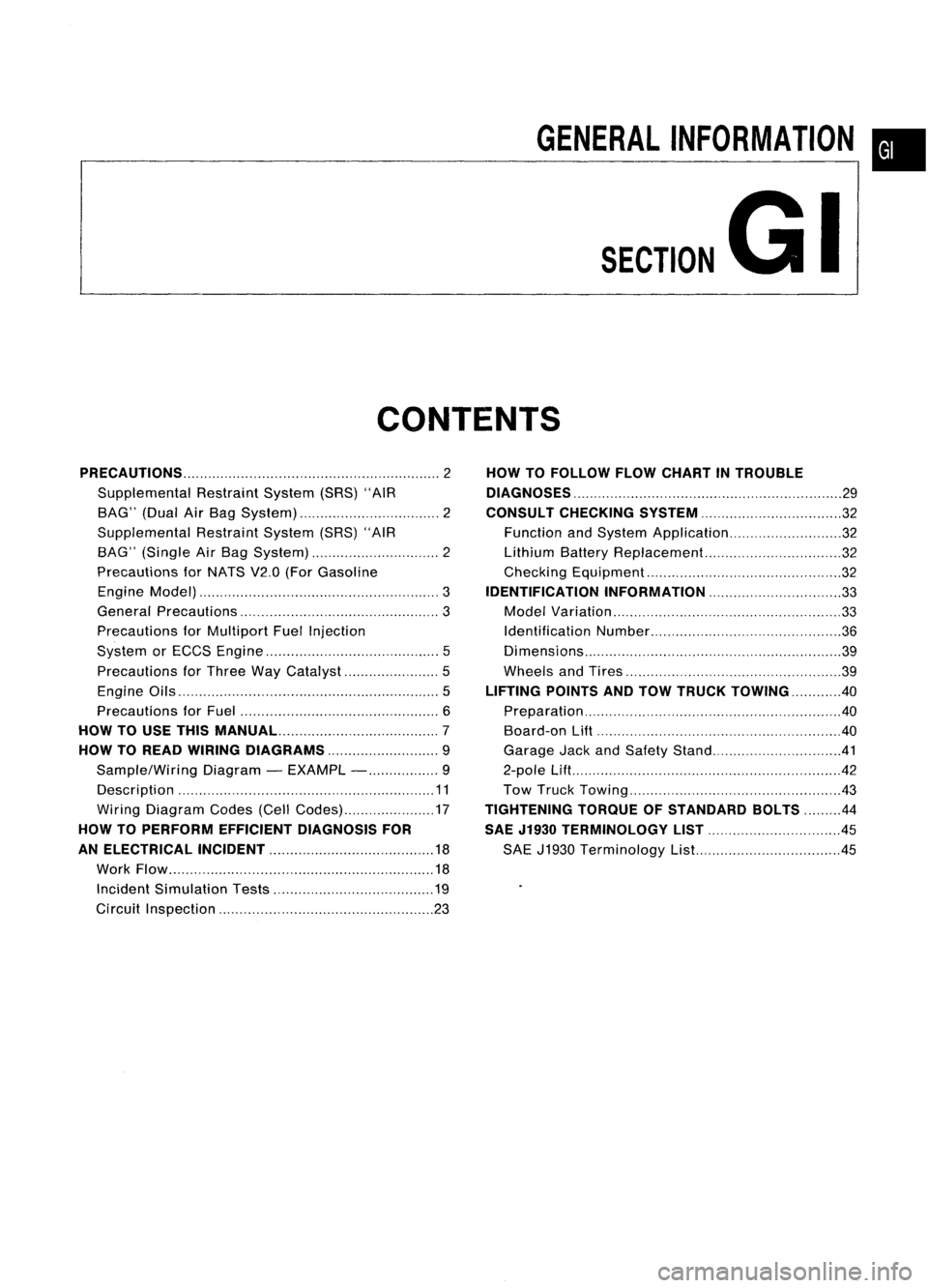
GENERALINFORMATION •
SECTION
G
I
CONTENTS
PRECAUTIONS 2
Supplemental RestraintSystem(SRS)"AIR
BAG" (DualAirBag System) 2
Supplemental RestraintSystem(SRS)"AIR
BAG" (Single AirBag System) 2
Precautions forNATS V2.0(ForGasoline
Engine Model) 3
General Precautions 3
Precautions forMultiport FuelInjection
System orECCS Engine 5
Precautions forThree WayCatalyst 5
Engine Oils 5
Precautions forFuel 6
HOW TOUSE THIS
MANUAL 7
HOW TOREAD WIRING DIAGRAMS 9
Sample/Wiring Diagram-EXAMPL - 9
Description 11
Wiring Diagram Codes(CellCodes) 17
HOW TOPERFORM EFFICIENT DIAGNOSIS FOR
AN ELECTRICAL INCIDENT 18
Work Flow 18
Incident Simulation Tests 19
Circuit Inspection 23
HOW
TOFOLLOW FLOWCHART INTROUBLE
DIAGNOSES 29
CONSULT CHECKING SYSTEM
32
Function andSystem Application 32
Lithium BatteryReplacement.. 32
Checking Equipment 32
IDENTIFICATION INFORMATION 33
Model Variation 33
Identification Number 36
Di mens ions 39
Wheels andTires 39
LIFTING POINTSANDTOW TRUCK TOWING ..40
Preparation 40
Board-on
Lift
40
Garage JackandSafety Stand 41
2-pole Lift 42
Tow Truck Towing 43
TIGHTENING TORQUEOFSTANDARD BOLTS
44
SAE J1930 TERMINOLOGY LIST 45
SAE J1930 Terminology List.. 45