1995 NISSAN ALMERA N15 battery replacement
[x] Cancel search: battery replacementPage 373 of 1701

ELECTRICALSYSTEM
SECTION
EL
When youread wiring diagrams:
• Read GIsection, "HOWTOREAD WIRING DIAGRAMS".
When youperform troublediagnos.es, readGIsection, "HOWTOFOllOW FLOWCHART
IN TROUBLE DIAGNOSES" and"HOW TOPERFORM EFFICIENT DIAGNOSIS FORAN
ELECTRICAL INCIDENT".
CONTENTS
PRECAUTIONS 4
Supplemental RestraintSystem(SRS)"AIR
BAG" (DualAirBag System) 4
Supplemental RestraintSystem(SRS)"AIR
BAG" (Single AirBag System) 4
HARNESS CONNECTOR 5
Description 5
STANDARDIZED RELAy 6
Description 6
POWER SUPPLY ROUTING 8
Schematic 8
Wiring Diagram -POWER - 10
Fuse 19
Fusible Link 19
Circuit Breaker 19
GROUND DISTRIBUTION 20
BATTERy 25
How toHandle Battery 25
Battery TestandCharging Chart.. 28
Service DataandSpecifications (SOS) 32
STARTING SySTEM
33
Wiring Diagram -START - 33
Trouble Diagnoses 35
Construction 36
Removal andInstallation .45
Magnetic SwitchCheck .46
Pinion/Clutch Check 46
Brush Check 46
Yoke Check 47
Armature Check 48
Assembly .49
Service DataandSpecifications (SDS) 50
CHARGING SYSTEM 52
Wiring Diagram -CHARGE - 52
Trouble Diagnoses 54Construction
55
Removal andInstallation 57
Disassembly 57
Rotor Check 57
Brush Check 58
Stator Check 58
Diode Check 59
Assembly 60
Service DataandSpecifications (SDS) 61
COMBINATION SWITCH 62
Combination Switch/Check 62
Replacement 64
HEADLAMP -Without Daytime lightSystem -65
Wiring Diagram -H/LAMP - 65
Trouble Diagnoses 67
HEADLAMP -Daytime lightSystem - 68
Operation (Daytimelightsystem) 68
System Description 69
Schematic 70
Wiring Diagram -DTRL - 71
Trouble Diagnoses (DaytimeLight) 74
HEADLAMP 75
Bulb Replacement... 75•
Aiming Adjustment. 75
HEADLAMP -Headlamp Aiming
Control- 77
Wiring Diagram -AIM - 77
Description 81
EXTERIOR LAMP 82
Clearance, LicenseandTail Lamps/Schematic 82
Clearance, LicenseandTail Lamps/Wiring
Diagram -TAILIL - 83
Stop Lamp/Wiring Diagram-STOP/L - 92
Back-up Lamp/Wiring Diagram-BACK/L -94
Front FogLamp/Wiring Diagram-F/FOG -96
Front FogLamp BulbReplacement 101
Page 447 of 1701
Bulbcover
SEL995K HEADLAMP
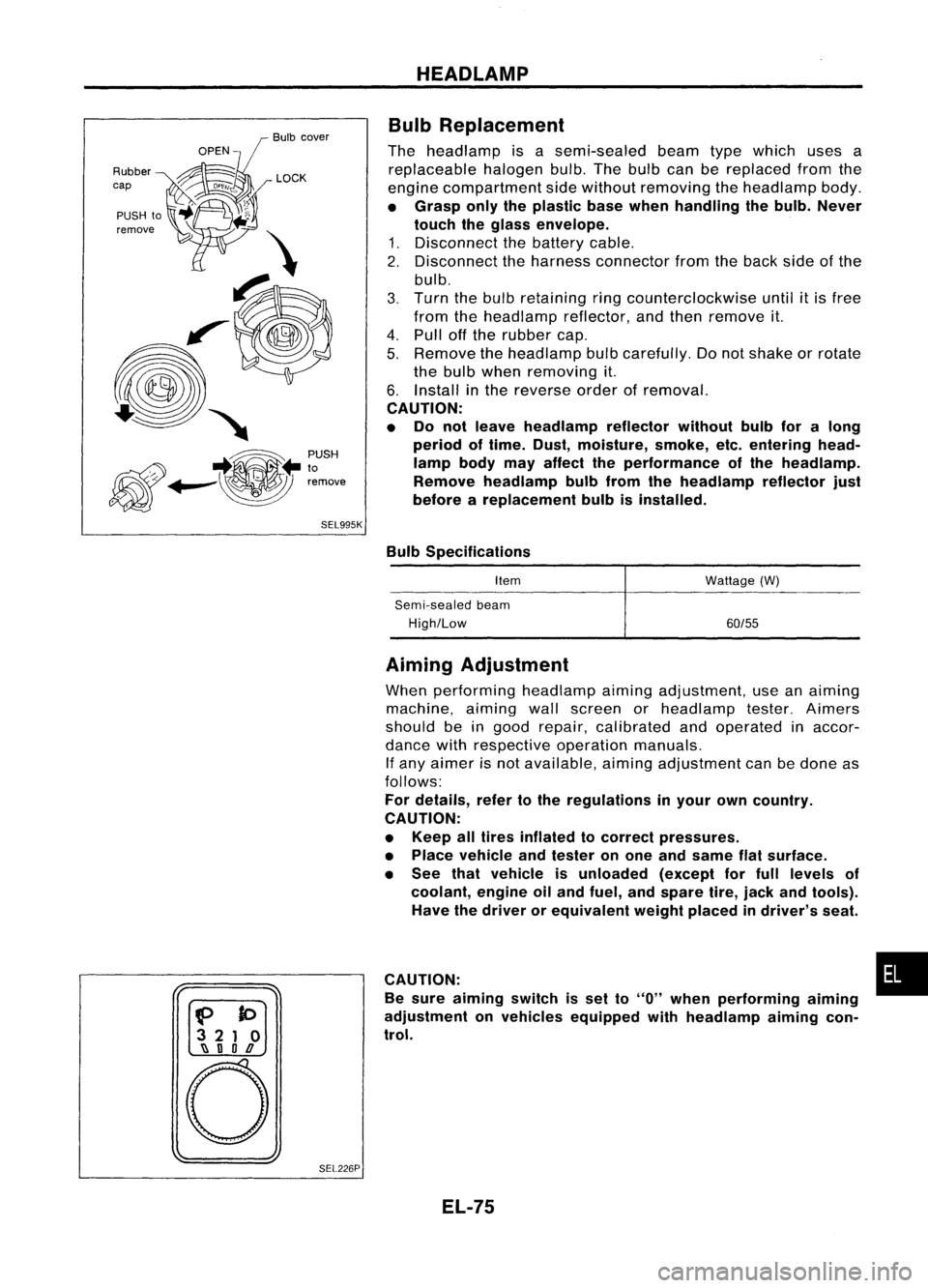
Bulb Replacement
The headlamp isasemi-sealed beamtypewhich usesa
replaceable halogenbulb.Thebulb canbereplaced fromthe
engine compartment sidewithout removing theheadlamp body.
• Grasp onlytheplastic basewhen handling thebulb. Never
touch theglass envelope.
1. Disconnect thebattery cable.
2. Disconnect theharness connector fromtheback sideofthe
bulb.
3. Turn thebulb retaining ringcounterclockwise until
it
is free
from theheadlamp reflector,andthen remove it.
4. Pull offthe rubber cap.
5. Remove theheadlamp bulbcarefully. Donot shake orrotate
the bulb when removing it.
6. Install inthe reverse orderofremoval.
CAUTION:
• Do not leave headlamp reflector withoutbulbforalong
period oftime. Dust,moisture, smoke,etc.entering head-
lamp bodymayaffect theperformance ofthe head lamp.
Remove headlamp bulbfrom thehead lamp reflector just
before areplacement bulbisinstalled.
Bulb Specifications
Item
Semi-sealed beam
High/Low Wattage
(W)
60/55
f>
to
3 21 0
~ nOD
o
SEL226PAiming
Adjustment
When performing headlamp aiming adjustment, useanaiming
machine, aimingwallscreen orheadlamp tester.Aimers
should beingood repair, calibrated andoperated inaccor-
dance withrespective operationmanuals.
If any aimer isnot available, aimingadjustment canbedone as
follows:
For details, refertothe regulations inyour owncountry.
CAUTION:
• Keep alltires inflated tocorrect pressures.
• Place vehicle andtester onone and same flatsurface.
• See thatvehicle isunloaded (exceptforfull levels of
coolant, engineoiland fuel, andspare tire,jack andtools).
Have thedriver orequivalent weightplaced indriver's seat.
CAUTION: •
Be sure aiming switchisset to
"0"
when performing aiming
adjustment onvehicles equipped withheadlamp aiming con-
trol.
EL-75
Page 473 of 1701
GEL001EXTERIOR
LAMP
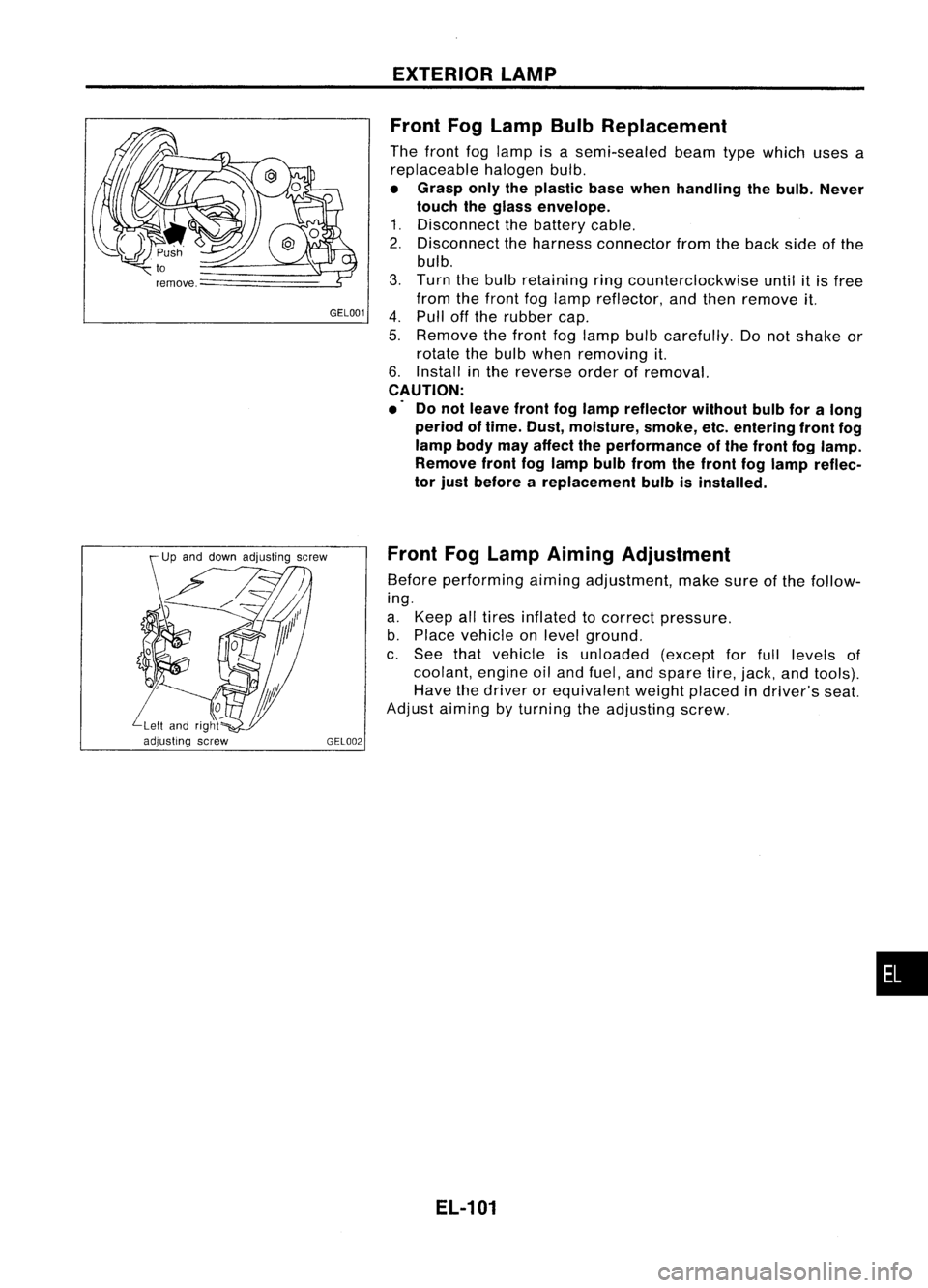
Front FogLamp BulbReplacement
The front foglamp isasemi-sealed beamtypewhich usesa
replaceable halogenbulb.
• Grasp onlytheplastic basewhen handling thebulb. Never
touch theglass envelope.
1. Disconnect thebattery cable.
2. Disconnect theharness connector fromtheback sideofthe
bulb.
3. Turn thebulb retaining ringcounterclockwise untilitis free
from thefront foglamp reflector, andthen remove it.
4. Pull offthe rubber cap.
5. Remove thefront foglamp bulbcarefully. Donot shake or
rotate thebulb when removing it.
6. Install inthe reverse orderofremoval.
CAUTION:
.' Donot leave frontfoglamp reflector withoutbulbforalong
period oftime. Dust, moisture, smoke,etc.entering frontfog
lamp bodymayaffect theperformance ofthe front foglamp.
Remove frontfoglamp bulbfrom thefront foglamp reflec-
tor just before areplacement bulbisinstalled.
Front FogLamp Aiming Adjustment
Before performing aimingadjustment, makesureofthe follow-
ing.
a. Keep alltires inflated tocorrect pressure.
b. Place vehicle onlevel ground.
c. See thatvehicle isunloaded (exceptforfull levels of
coolant, engineoiland fuel, andspare tire,jack, andtools).
Have thedriver orequivalent weightplaced indriver's seat.
Adjust aiming byturning theadjusting screw.
EL-101
•
Page 1355 of 1701
GENERALINFORMATION •
SECTION
G
I
CONTENTS
PRECAUTIONS 2
Supplemental RestraintSystem(SRS)"AIR
BAG" (DualAirBag System) 2
Supplemental RestraintSystem(SRS)"AIR
BAG" (Single AirBag System) 2
Precautions forNATS V2.0(ForGasoline
Engine Model) 3
General Precautions 3
Precautions forMultiport FuelInjection
System orECCS Engine 5
Precautions forThree WayCatalyst 5
Engine Oils 5
Precautions forFuel 6
HOW TOUSE THIS
MANUAL 7
HOW TOREAD WIRING DIAGRAMS 9
Sample/Wiring Diagram-EXAMPL - 9
Description 11
Wiring Diagram Codes(CellCodes) 17
HOW TOPERFORM EFFICIENT DIAGNOSIS FOR
AN ELECTRICAL INCIDENT 18
Work Flow 18
Incident Simulation Tests 19
Circuit Inspection 23
HOW
TOFOLLOW FLOWCHART INTROUBLE
DIAGNOSES 29
CONSULT CHECKING SYSTEM
32
Function andSystem Application 32
Lithium BatteryReplacement.. 32
Checking Equipment 32
IDENTIFICATION INFORMATION 33
Model Variation 33
Identification Number 36
Di mens ions 39
Wheels andTires 39
LIFTING POINTSANDTOW TRUCK TOWING ..40
Preparation 40
Board-on
Lift
40
Garage JackandSafety Stand 41
2-pole Lift 42
Tow Truck Towing 43
TIGHTENING TORQUEOFSTANDARD BOLTS
44
SAE J1930 TERMINOLOGY LIST 45
SAE J1930 Terminology List.. 45
Page 1386 of 1701
CONSULTCHECKING SYSTEM
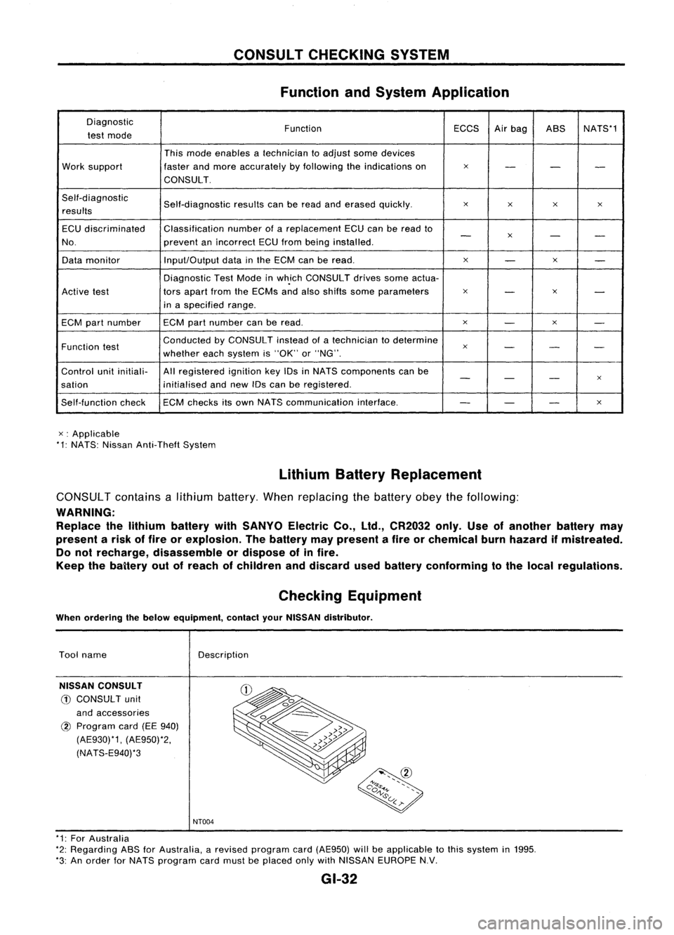
Function andSystem Application
Diagnostic FunctionECCSAirbag ASS NATS*1
test mode
Thismode enables atechnician toadjust somedevices
Work support fasterandmore accurately byfollowing theindications on
x
- --
CONSULT.
Self-diagnostic Self-diagnosticresultscanberead anderased quickly.
x
x x
x
results
ECU discriminated Classification
numberofareplacement ECUcanberead to
-
x
- -
No. preventanincorrect ECUfrom being installed.
Data monitor Input/Output
datainthe ECM canberead.
x
-
x
-
Diagnostic TestMode inwh.ich CONSULT drivessomeactua-
Active test tors
apart fromtheECMs andalso shifts some parameters
x
-
x
-
in aspecified range.
ECM partnumber ECM
partnumber canberead.
x
-
x
-
Function test Conducted
byCONSULT insteadofatechnician todetermine
x
- --
whether eachsystem is"OK" or"NG".
Control unitinitiali- Allregistered ignitionkeyIDsinNATS components canbe
- -
-
x
sation initialisedandnew IDscan beregistered.
Self-function checkECM
checks itsown NATS communication interface.
--
-
x
x :Applicable
*1: NATS: Nissan Anti-Theft System
LithiumBatteryReplacement
CONSUL Tcontains alithium battery. Whenreplacing thebattery obeythefollowing:
WARNING: Replace thelithium battery withSANYO ElectricCo.,ltd., CR2032 only.Useofanother batterymay
present arisk offire orexplosion. Thebattery maypresent afire orchemical burnhazard ifmistreated.
Do not recharge, disassemble ordispose ofinfire.
Keep thebaitery outofreach ofchildren anddiscard usedbattery conforming tothe local regulations.
Checking Equipment
When ordering thebelow equipment, contactyourNISSAN distributor.
Tool name
NISSAN CONSULT
CD
CONSULT unit
and accessories
@
Program card(EE940)
(AE930)*1, (AE950)*2,
(NATS-E940)*3 Description
NT004
* 1: For Australia
*2: Regarding ASSforAustralia, arevised program card(AE950) willbeapplicable tothis system in1995.
*3: An order forNATS program cardmust beplaced onlywithNISSAN EUROPE N.V.
GI-32
Page 1632 of 1701
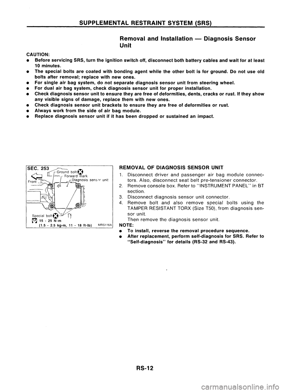
SUPPLEMENTALRESTRAINTSYSTEM(SRS)
Removal andInstallation -Diagnosis Sensor
Unit
CAUTION:
• Before servicing SRS,turntheignition switchoff,disconnect bothbattery cablesandwait foratleast
10 minutes.
• The special boltsarecoated withbonding agentwhiletheother boltisfor ground. Donot use old
bolts afterremoval; replacewithnewones.
• For single airbag system, donot separate diagnosis sensorunitfrom steering wheel.
• For dual airbag system, checkdiagnosis sensorunitforproper installation.
• Check diagnosis sensorunittoensure theyarefree ofdeformities, dents,cracks orrust. Ifthey show
any visible signsofdamage, replacethemwithnewones.
• Check diagnosis sensorunitbrackets toensure theyarefree ofdeformities orrust.
• Always workfromtheside ofair bag module.
• Replace diagnosis sensorunitifithas been dropped orsustained animpact.
SEC. 253~
IT
r
Grou~? bolt~
G ~~ ~
Forward mark
Fr?nt
_--I
d--!
Dia~no:iS senSlrunit
!
Special bOIt~ -
t"'J
15-25 N.m
(1.5 •2.5 kg-m,
11-
18 ft-Ib)
MRS116A REMOVAL
OFDIAGNOSIS SENSORUNIT
1. Disconnect driverandpassenger airbag module connec-
tors. Also, disconnect seatbeltpre-tensioner connector.
2. Remove consolebox.Refer to"INSTRUMENT PANEL"in8T
section.
3. Disconnect diagnosissensorunitconnector.
4. Remove boltandalso remove specialboltsusing the
TAMPER RESISTANT TORX(SizeT50),fromdiagnosis sen-
sor unit.
Then remove thediagnosis sensorunit.
NOTE:
• Toinstall, reverse theremoval procedure sequence.
• After replacement, performself-diagnosis forSRS. Refer to
"Self-diagnosis" fordetails (RS-32andRS-43).
RS-12
Page 1654 of 1701
•SELF-DIAG RESULTS.
0
FAILURE DETECTED
• NO SELF DIAGNOSTIC
FAILURE INDICATED.
TROUBLE
DIAGNOSES -Supplemental RestraintSystem(SRS)-
Dual AirBag System
Self-diagnosis (Cont'd)
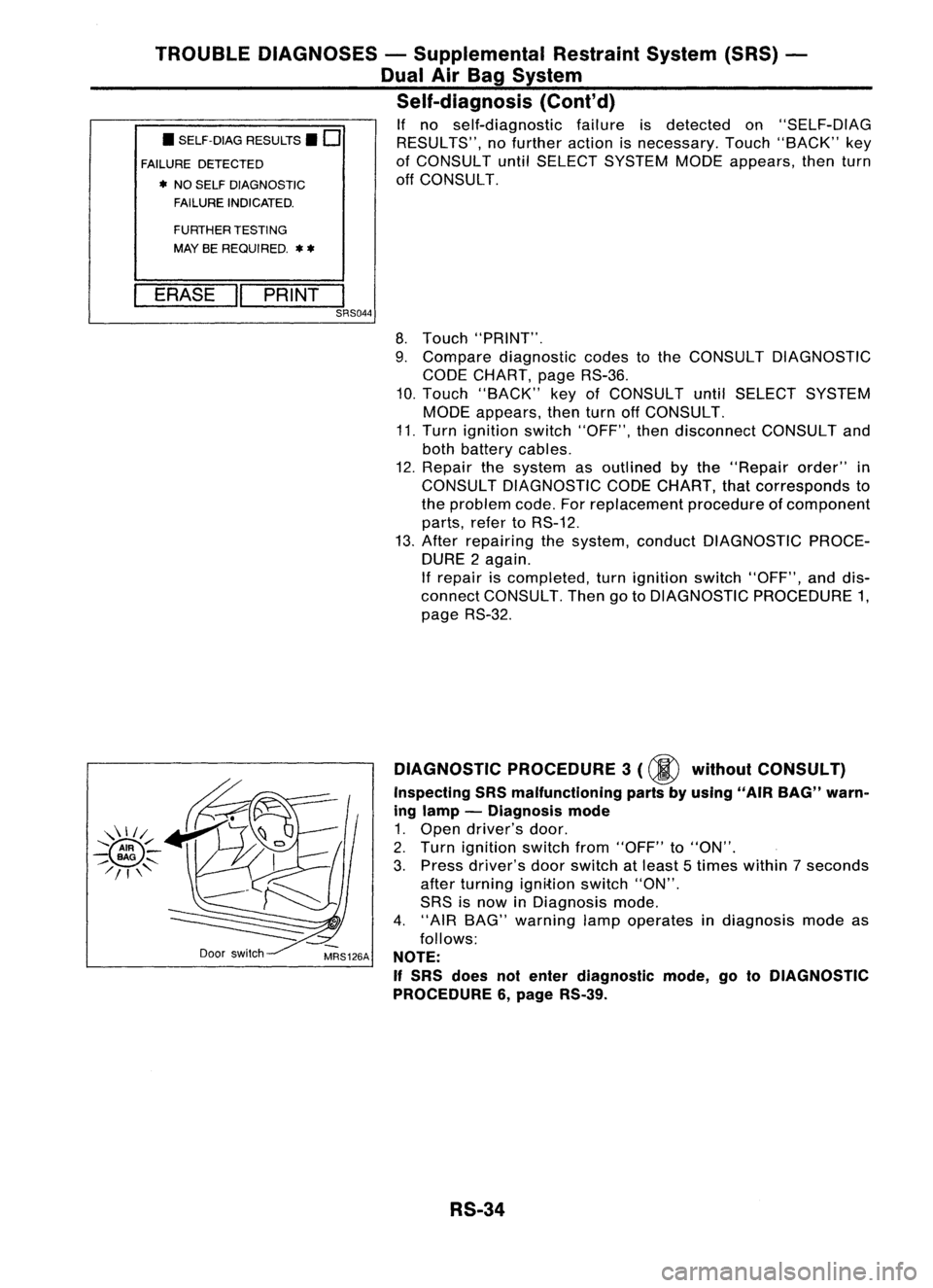
If no self-diagnostic failureisdetected on"SELF-DIAG
RESULTS", nofurther actionisnecessary. Touch"BACK" key
of CONSULT untilSELECT SYSTEM MODEappears, thenturn
off CONSULT.
FURTHER TESTING
MAY BEREQUIRED.
**
ERASE "PRINT
I
SRS044
8.Touch "PRINT".
9. Compare diagnostic codestothe CONSULT DIAGNOSTIC
CODE CHART, pageRS-36.
10. Touch "BACK" keyofCONSULT untilSELECT SYSTEM
MODE appears, thenturnoffCONSULT.
11. Turn ignition switch"OFF", thendisconnect CONSULTand
both battery cables.
12. Repair thesystem asoutlined bythe "Repair order"in
CONSULT DIAGNOSTIC CODECHART, thatcorresponds to
the problem code.Forreplacement procedureofcomponent
parts, refertoRS-12.
13. After repairing thesystem, conduct DIAGNOSTIC PROCE-
DURE 2again.
If repair iscompleted, turnignition switch"OFF", anddis-
connect CONSULT. ThengotoDIAGNOSTIC PROCEDURE 1,
page RS-32.
Door switch DIAGNOSTIC
PROCEDURE 3
(00
without CONSULT)
Inspecting SRSmalfunctioning partsbyusing "AIRBAG" warn-
ing lamp -Diagnosis mode
1. Open driver's door.
2. Turn ignition switchfrom"OFF" to"ON".
3. Press driver's doorswitch atleast 5times within 7seconds
after turning ignition switch"ON".
SRS isnow inDiagnosis mode.
4. "AIR BAG" warning lampoperates indiagnosis modeas
follows:
NOTE:
If
SRS does notenter diagnostic mode,gotoDIAGNOSTIC
PROCEDURE 6,page RS-39.
RS-34
Page 1655 of 1701
TROUBLEDIAGNOSES -Supplemental RestraintSystem(SRS)-
Dual AirBag System
Self-diagnosis (Cont'd)
No.
ON
OFF
IGN
ON
t
"AIR
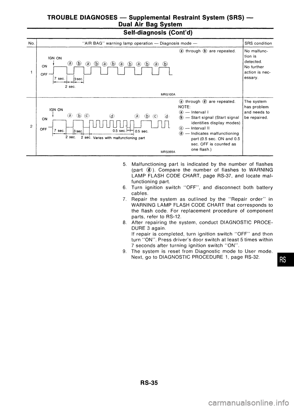
BAG" warning lampoperation -Diagnosis mode-
@
through
@
are repeated.
MRS100A
SRS
condition
No malfunc-
tion is
detected. No further
action isnec-
essary.
2 ON
OFF
IGN
ON
I
7 sec.
@)
@
(c)
3sec.
2 sec. 2sec. Varies withmalfunctioning part
MRS099A
@
through
@
are repeated.
NOTE: @ -
Interval I
@ -
Start signal (Startsignal
identifies displaymodes)
@ -
Interval II
@ -
Indicates malfunctioning
part (0.5sec. ONand 0.5
sec. OFF iscounted as
one flash.) The
system
has problem
and needs to
be repaired.
5. Malfunctioning partisindicated bythe number offlashes
(part
@).
Compare thenumber offlashes toWARNING
LAMP FLASH CODECHART, pageRS-37, andlocate mal-
functioning part.
6. Turn ignition switch"OFF", anddisconnect bothbattery
cables.
7. Repair thesystem asoutlined bythe "Repair order"in
WARNING LAMPFLASH CODECHART thatcorresponds to
the flash code. Forreplacement procedureofcomponent
parts, refertoRS-12.
8. After repairing thesystem, conduct DIAGNOSTIC PROCE-
DURE 3again.
If repair iscompleted, turnignition switch"OFF"andthen
turn "ON". Pressdriver's doorswitch atleast 5times within
7 seconds afterturning ignition switch"ON".
9. The system isreset fromDiagnostic modetoUser mode.
Next, gotoDIAGNOSTIC PROCEDURE 1,page RS-32. •
RS-35