Page 687 of 1701
SMA525AON-VEHICLE
SERVICE
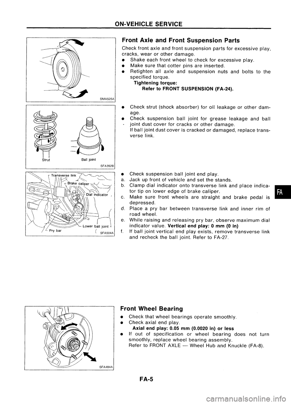
Front AxleandFront Suspension Parts
Check frontaxleandfront suspension partsforexcessive play,
cracks, wearorother damage.
• Shake eachfrontwheel tocheck forexcessive play.
• Make surethatcotter pinsareinserted.
• Retighten allaxle andsuspension nutsandbolts tothe
specified torque.
Tightening torque:
Refer toFRONT SUSPENSION (FA-24).
Strut
Ball
joint
SFA392B
•
Check strut(shock absorber) foroilleakage orother dam-
age.
• Check suspension balljoint forgrease leakage andball
joint dustcover forcracks orother damage.
If ball joint dustcover iscracked ordamaged, replacetrans-
verse link.
• Check suspension balljoint endplay.
a. Jack upfront ofvehicle andsetthe stands.
b. Clamp dialindicator ontotransverse linkand place indica- •
tor tiponlower edgeofbrake caliper. •
c. Make surefront wheels arestraight andbrake pedalis
depressed.
d. Place apry bar between transverse linkand inner rimof
road wheel.
e. While raising andreleasing prybar, observe maximum dial
indicator value.
Vertical endplay: 0mm (0in)
f. Ifball joint vertical endplay exists, remove transverse link
and recheck theball joint. Refer toFA-27.
SFA484A Front
Wheel Bearing
• Check thatwheel bearings operatesmoothly.
• Check axialendplay.
Axial endplay: 0.05mm(0.0020 in)orless
• If
out ofspecification orwheel bearing doesnotturn
smoothly, replacewheelbearing assembly.
Refer toFRONT AXLE-Wheel HubandKnuckle (FA-B).
FA-5
Page 712 of 1701
SERVICEDATAANDSPECIFICATIONS (SDS)
Inspection andAdjustment (Cont'd)
Nissan genuine greaseorequivalent
g
(oz)
Grease
Capacity
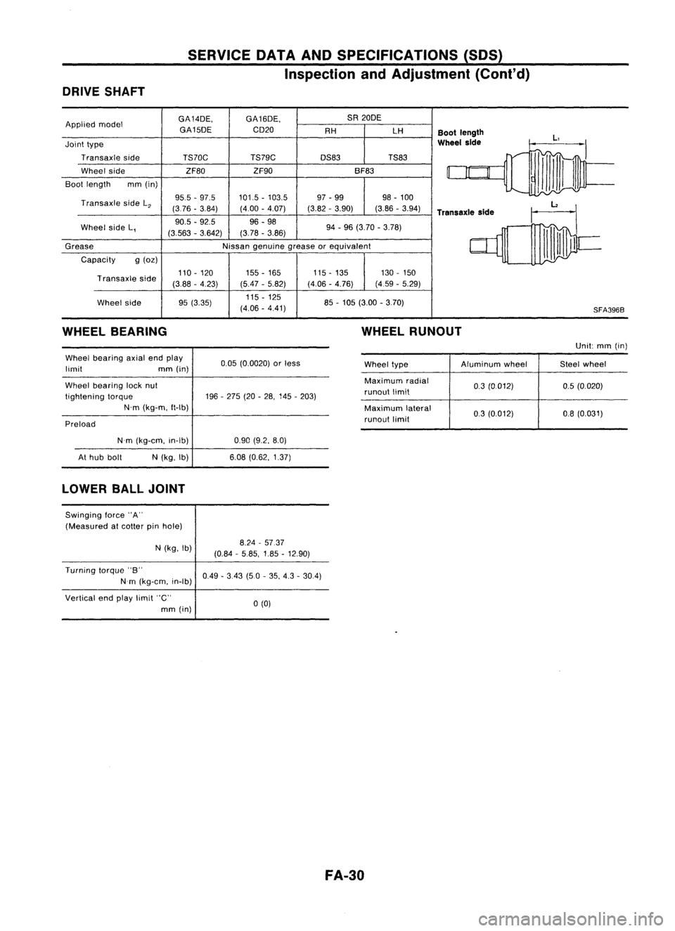
DRIVE
SHAFT
GA14DE,GA16DE, SA
20DE
Applied model
GA15DECD20
AHLH
Bootlength
Joint type
Wheel
side
Transaxle side TS70C TS79C
DS83TS83
Wheel side ZF80ZF90 BF83
Boot length mm(in)
Transaxle sideL
2
95.5
-97.5 101.5-103.5 97
-99 98-100
(376 -3.84) (4.00-4.07) (3.82-3.90) (3.86-3.94)
Transaxle side
Wheel sideL, 90.5
-92.5 96-98
94-96 (3.70 -3.78)
(3.563 -3.642) (3.78
-3.86)
85-105 (3.00 -3.70)
Transaxle
side
Wheel side 110
-120
(388 -4.23)
95 (3.35) 155
-165
(5.47 -5.82)
115 -125
(4.06 -4.41) 115
-135
(4.06 -4.76) 130
-150
(4.59 -5.29)
SFA3968
WHEEL BEARING WHEEL
RUNOUT
Unit:mm(in)
Wheel bearing axialendplay
limit mm(in)
Wheel bearing locknut
tightening torque
N'm (kg-m, ft-Ib)
Preload 0.05
(0.0020) orless
196 -275 (20-28, 145 -203) Wheel
type Aluminum
wheel Steelwheel
Maximum radial
0.3(0.012) 0.5(0.020)
runout limit
Maximum lateral
03(0.012) 0.8(0.031)
runout limit
N'm (kg-em, in-Ib)
At hub bolt
N
(kg, Ib)
0.90
(9.2, 8.0)
6.08 (0.62, 1.37)
LOWER BALLJOINT
Swinging force"A"
(Measured atcotter pinhole)
N (kg, Ib)
8.24
-5737
(0.84 -5.85, 1.85-12.90)
Turning torque"B"
Nm (kg-em, in-Ib)
Vertical endplay limit "C"
mm (in)
0.49
-3.43 (5.0-35, 4.3 -30.4)
0(0)
FA-30
Page 1355 of 1701
GENERALINFORMATION •
SECTION
G
I
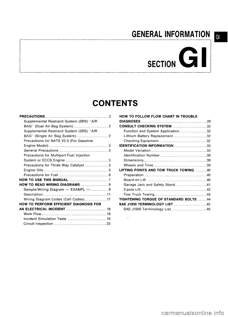
CONTENTS
PRECAUTIONS 2
Supplemental RestraintSystem(SRS)"AIR
BAG" (DualAirBag System) 2
Supplemental RestraintSystem(SRS)"AIR
BAG" (Single AirBag System) 2
Precautions forNATS V2.0(ForGasoline
Engine Model) 3
General Precautions 3
Precautions forMultiport FuelInjection
System orECCS Engine 5
Precautions forThree WayCatalyst 5
Engine Oils 5
Precautions forFuel 6
HOW TOUSE THIS
MANUAL 7
HOW TOREAD WIRING DIAGRAMS 9
Sample/Wiring Diagram-EXAMPL - 9
Description 11
Wiring Diagram Codes(CellCodes) 17
HOW TOPERFORM EFFICIENT DIAGNOSIS FOR
AN ELECTRICAL INCIDENT 18
Work Flow 18
Incident Simulation Tests 19
Circuit Inspection 23
HOW
TOFOLLOW FLOWCHART INTROUBLE
DIAGNOSES 29
CONSULT CHECKING SYSTEM
32
Function andSystem Application 32
Lithium BatteryReplacement.. 32
Checking Equipment 32
IDENTIFICATION INFORMATION 33
Model Variation 33
Identification Number 36
Di mens ions 39
Wheels andTires 39
LIFTING POINTSANDTOW TRUCK TOWING ..40
Preparation 40
Board-on
Lift
40
Garage JackandSafety Stand 41
2-pole Lift 42
Tow Truck Towing 43
TIGHTENING TORQUEOFSTANDARD BOLTS
44
SAE J1930 TERMINOLOGY LIST 45
SAE J1930 Terminology List.. 45
Page 1612 of 1701
SMA525A
SMA113
---I
SRA690A ON-VEHICLE
SERVICE
Rear AxleandRear Suspension Parts
Check axleandsuspension partsforexcessive play,wear or
damage.
• Shake eachrearwheel tocheck forexcessive play.
• Retighten allnuts andbolts tothe specified torque.
Tightening torque:
Refer toREAR SUSPENSION (RA-8).
• Check shockabsorber for
oil
leakage orother damage.
Rear Wheel Bearing
• Check axialendplay.
Axial endplay:
0.05 mm(0.0020 in)orless
• Check thatwheel hubbearings operatesmoothly.
• Check tightening torqueofwheel bearing locknut.
(OJ:
186 •255 N.m (19-26 kg-m, 137•188 ft-Ib)
• Replace wheelbearing assembly ifthere isaxial endplay
or wheel bearing doesnotturn smoothly. RefertoREAR
AXLE -Wheel Hub(RA-6).
RA-4
Page 1617 of 1701
SRA696A
SRA697A
S
Control rod
Lateral link
~H";""I"
ITorsion
beam
SRA698AREAR
SUSPENSION
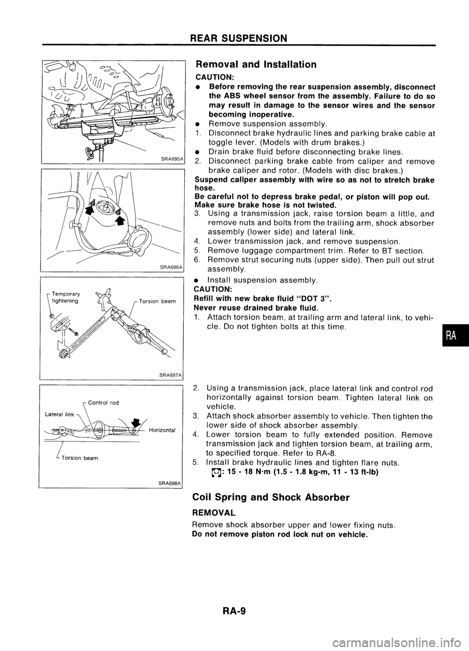
Removal andInstallation
CAUTION:
• Before removing therear suspension assembly,disconnect
the ABS wheel sensor fromtheassembly. Failuretodo so
may result indamage tothe sensor wiresandthesensor
becoming inoperative.
• Remove suspension assembly.
1. Disconnect brakehydraulic linesandparking brakecableat
toggle lever.(Models withdrum brakes.)
• Drain brake fluidbefore disconnecting brakelines.
2. Disconnect parkingbrakecablefromcaliper andremove
brake caliper androtor. (Models withdiscbrakes.)
Suspend caliperassembly withwire soasnot tostretch brake
hose.
Be careful nottodepress brakepedal, orpiston willpop out.
Make surebrake hoseisnot twisted.
3. Using atransmission jack,raise torsion beamalittle, and
remove nutsandbolts fromthetrailing arm,shock absorber
assembly (lowerside)andlateral link.
4. Lower transmission jack,andremove suspension.
5. Remove luggagecompartment trim.Refer toBT section.
6. Remove strutsecuring nuts(upper side).Thenpulloutstrut
assembly.
• Install suspension assembly.
CAUTION: Refill withnewbrake fluid"DOT
3".
Never reusedrained brakefluid.
1. Attach torsion beam,attrailing armandlateral link,tovehi-
cle. Donot tighten boltsatthis time.
2. Using atransmission jack,place lateral linkand control rod
horizontally againsttorsionbeam.Tighten laterallinkon
vehicle.
3. Attach shockabsorber assembly tovehicle. Thentighten the
lower sideofshock absorber assembly.
4. Lower torsion beamtofully extended position.Remove
transmission jackandtighten torsion beam,attrailing arm,
to specified torque.RefertoRA-8.
5. Install brakehydraulic linesandtighten flarenuts.
~: 15-18 N'm (1.5.1.8 kg-m,11-13 ft-Ib)
Coil Spring andShock Absorber
REMOVAL
Remove shockabsorber upperandlower fixing nuts.
Do not remove pistonrodlock nutonvehicle.
RA-9
•
Page 1686 of 1701
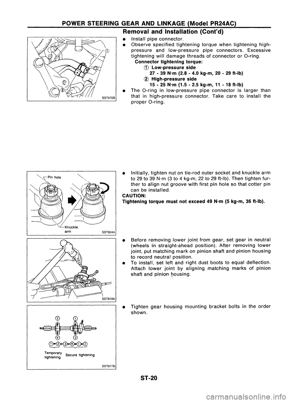
POWERSTEERING GEARANDLINKAGE (ModelPR24AC)
Removal andInstallation (Cont'd)
• Install pipeconnector.
• Observe specified tightening torquewhentightening high-
pressure andlow-pressure pipeconnectors. Excessive
tightening willdamage threadsofconnector orO-ring.
Connector tighteningtorque:
CD
Low-pressure side
27 -39 N'm (2.8-4.0 kg-m, 20-29 ft-Ib)
~ High-pressure side
15 -25 N'm (1.5-2.5 kg-m, 11-18 ft-Ib)
• The O-ring inlow-pressure pipeconnector islarger than
that inhigh-pressure connector.Takecaretoinstall the
proper O-ring.
• Initially, tightennutontie-rod outersocket andknuckle arm
to 29 to39 N'm (3to 4kg-m, 22to29 ft-Ib). Thentighten fur-
ther toalign nutgroove withfirstpinhole sothat cotter pin
can beinstalled.
CAUTION:
Tightening torquemustnotexceed 49N'm (5kg-m, 36ft-Ib).
• Before removing lowerjointfrom gear, setgear inneutral
(wheels instraight-ahead position).Afterremoving lower
joint, putmatching markonpinion shaftandpinion housing
to record neutral position.
• Toinstall, setleftand right dustboots toequal deflection.
Attach lowerjointbyaligning matching marksofpinion
shaft andpinion ~ousing.
• Tighten gearhousing mounting bracketboltsinthe order
shown.
o
@
~
'--v---' ~
Temporary ..
tightening SecuretIghtening
SST6778
ST-20