Page 3 of 1701

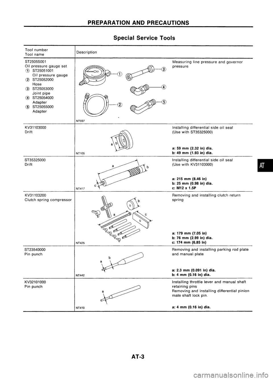
Toolnumber
Tool name
PREPARATION
ANDPRECAUTIONS
Special Service Tools
Description
8T25058001
Oil pressure gaugeset
G)
8T25051001
Oil pressure gauge
@ 8T25052000
Hose
@
8T25053000
Joint pipe
@
8T25054000
Adapter
@
8T25055000
Adapter Measuring
linepressure andgovernor
pressure
NT097
KV31103000
Drift
8T35325000 Drift
KV31103200
Clutch spring compressor
8T23540000 Pin punch
KV32101000
Pin punch
NT105
NT417
NT425
NT442
NT410
AT-3
Installing
differential sideoilseal
(Use with8T35325000)
a: 59 mm (2.32 in)dia.
b: 49 mm (1.93 in)dia.
Installing differential sideoilseal
(Use withKV31103000)
a: 215 mm (8.46 in)
b: 25 mm (0.98 in)dia.
c: M12 x1.5P
Removing andinstalling clutchreturn
spring
a: 179 mm (7.05 in)
b: 76 mm (2.99 in)dia.
c: 174 mm (6.85 in)
Removing andinstalling parkingrodplate
and manual plate
a: 2.3 mm (0.091 in)dia.
b: 4mm (0.16 in)dia.
Installing throttleleverandmanual shaft
retaining pins
Removing andinstalling differential pinion
mate shaft lockpin.
a: 4mm (0.16 in)dia.
•
Page 10 of 1701
MODEL34X68
4th
speed cut
valve
Overrunclutch
control
valve
Lock-up
control
valve
Torque '~..•.•
converter
>..•.••••
relief ..••.....
valve ..
Governor
valve
X:Drain port
: Orifice DESCRIPTION
Hydraulic ControlCircuit
Low
&
reverse
brake
High clutch
Detent valve
AT-10 Forward
clutch
1-2
shift
valve
SAT1961
Page 11 of 1701
MODEL34X69AND34X70 DESCRIPTION
Hydraulic ControlCircuit(Cont'd)
00 cancel
solenoid
Lock-up
control
valve
X :
Drain port
•
1-2
shift valve
Forward
clutch
accumulator
valve
High
clutch
Torque
converter
Oil
pump
i
=:= :
Orifice
Overrun
clutch
II
control
valve
4th
speed
cut
valve
SAT509H
AT-11
Page 12 of 1701

DESCRIPTION
Hydraulic ControlCircuit(Cont'd)
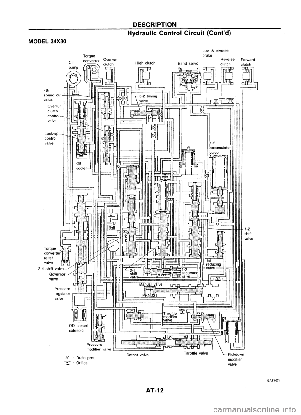
MODEL 34X80
1-2
shift
valve
1-2
accumulator
valve
~ 1
i i
xU
::l.
x
-
Detent valve
L-
_
-
cooler- Low
&
reverse
Torque brake
Oil converter Overrun ReverseForward
I
,clutch Highclutch Bandservo clutchclutch
pump
I
tJ
(Jp::-
(T,
tf1
--;::;-;r.]O~
~J
1~
g~ (~ ~~
l]
J~ ~
~iJ -
N
~%~
UL"-'
IU4~1~~
C-1
-!
~frEJ!
1
6 ~, -~
m
~,--J
0
- ILJ
,-O...J
r
ar
r::r=< I'---,
II .(
I'
IJ
,'-
~
,,'
(
-
I -
=-
~tL ',
~H
I~
~ ~M~ ·
F=
f='l .,.11
1-
~I" ~
" ~r'
I
L...---...l
reducing_
L
2-3 .4-2
I
~valve= ~
shift ~seq!!.enc~
~ -valve ,-=-valve---j
h
1J;;;.Q"t....
=--=-.J
II
Ma~alve
lJl.
"~'L--.J
:;;; ~I 11
p
URNb'21
nn
=-.--'
I~
II
'i-V
D
I I -,
." c:
I
Throttle
':fj'~1 .
modifier
If.'
valve .
II
I
1"
";'Jnn!
l...,
:=~-' \~
Throttle valve ~Klckdown
modifier
valve
X
:Drain port
:::::: :Orifice
Pressure
regulator
valve
!lJF
D
00 cancel
I
~Y&
solenoid •
Pressure
modifier valve
Lock-up_
control
valve
4th
speed cut
valve
Overrun
clutch
control-
valve
-=~
I
r
rr=-
LL:
J~
L~
Torque
x'"~
converter
i
i
relief '
valve
2~ '-
3-4 shift valv~-HiliJI
Governor../l ..-
valve
SAT1971
AT-12
Page 13 of 1701
MODEL34X81
4th speed
cut valve
Lock-up
control valve
Overrun
clutch
control valve
3-4 shift valve
X Drainport
:::::= :
Orifice Oil
pump Torque
converter DESCRIPTION
Hydraulic ControlCircuit(Cont'd)
High clutch
AT-13 1-2
shift valve
SAT1981
•
Page 14 of 1701

DESCRIPTION
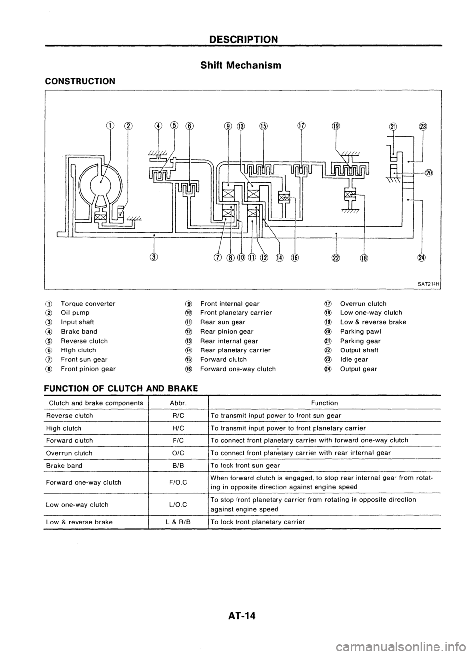
Shift Mechanism
CONSTRUCTION
18
,:-1
SAT214H
ill
Torque converter
@
Oilpump
@
Input shaft
@
Brake band
@
Reverse clutch
@
High clutch
o
Front sungear
@
Front pinion gear
@
Front internal gear
@l
Front planetary carrier
@
Rear sungear
@
Rear pinion gear
@
Rear internal gear
@
Rear planetary carrier
@
Forward clutch
@
Forward one-way clutch
@
Overrun clutch
@
Lowone-way clutch
@
Low
&
reverse brake
@
Parking pawl
@
Parking gear
@
Output shaft
@
Idlegear
@
Output gear
FUNCTION OFCLUTCH ANDBRAKE
Glutch andbrake components Abbr. Function
Reverse clutch
RIG
To
transmit inputpower tofront sungear
High clutch
HIG
To
transmit inputpower tofront planetary carrier
Forward clutch
FIG
To
connect frontplanetary carrierwithforward one-way clutch
Overrun clutch
OIG
To
connect frontplanetary carrierwithrearinternal gear
Brake band BIBTo
lock front sungear
Forward one-way clutch
F/O.G
When
forward clutchisengaged, tostop rearinternai gearfrom rotat-
ing inopposite direction againstenginespeed
Low one-way clutch LlO.GTo
stop front planetary carrierfromrotating inopposite direction
against enginespeed
Low
&
reverse brake L
&
RIB To
lock front planetary carrier
AT-14
Page 15 of 1701

DESCRIPTION
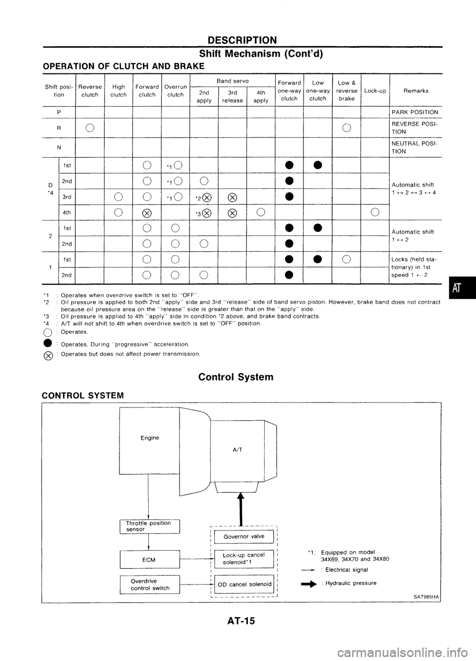
Shift Mechanism (Cont'd)
OPERATION OFCLUTCH ANDBRAKE
Bandservo
ForwardLow
Low
&
Shift posi- Reverse
HighForward
Overrun
Lock-upRemarks
tion clutch clutchclutchclutch 2nd
3rd4thone-way
one-way reverse
apply release
applyclutch
clutch brake
P PARK
POSITION
0 0REVERSE
POSI-
R TION
N NEUTRAL
POSI-
TION
1st 0'10
••
D 2nd
0'10
0
•
Automatic
shift
'4 00'10
'2@
@
•
1<-->2<-->3<-->4
3rd
4th 0@ '3@
@0
0
1st 00
••
Automatic
shift
2 1<-->2
2nd 00 0
•
1st 00
•
•
0
Locks
(heldsta-
1 tionary)
in1st
2nd 00 0
•
speed
1
<--
2
'1 Operates whenoverdrive switchissel to"OFF".
'2 Oilpressure isapplied toboth 2nd"apply" sideand3rd"release" sideofband servo piston. However, brakebanddoes notcontract
because oilpressure areaonthe "release" sideisgreater thanthatonthe "apply" side.
'3 Oilpressure isapplied to4th "apply" sideincondition '2above, andbrake bandcontracts.
'4 AIT
will notshift to4th when overdrive switchisset to"OFF" position.
o
Operates.
• Operates. During"progressive" acceleration.
@ Operates butdoes notaffect power transmission.
Control System
CONTROL SYSTEM
Engine
AIT
•
Lock-up cancel
solenoid'1
Overdrive
control switch
1:1
Governor valve
I
11
1
I
1
1
OD cancel solenoid :
; I
L
J
AT-15
'1:
Equipped onmodel
34X69, 34X70and34X80
: Electrical signal
.... :Hydraulic pressure
SAT985HA
Page 17 of 1701

Fluidleakage TROUBLE
DIAGNOSES
Preliminary Check(PriortoRoad Testing)
AIT FLUID CHECK
Fluid leakage check
1. Clean areasuspected ofleaking, -for example, mating
surface ofconverter housingandtransmission case.
2. Start engine, applyfootbrake, placeselector leverin"0"
position andwait afew minutes.
3. Stop engine.
4. Check forfresh leakage.
SAT288G
Fluidcondition check
Fluid levelcheck -Refer toMA section (CHASSIS AND
BODY MAINTENANCE).
Fluid
color
Oark orblack withburned odor
Milky pink
Varnished fluid,lighttodark brown
and tacky Suspected
problem
Wear offrictional material
Water contamination
- Road water entering through
filler tubeorbreather
Oxidation
- Over orunder filling
- Overheating
•
Road Testing
Perform roadtests using "Symptom" chart.Refertopage
AT-20.
"P"
POSITION
1. Place selector leverin"P" position andstart engine. Stop
engine andrepeat theprocedure inall positions, including
neutral position.
2. Stop vehicle onaslight upgrade andplace selector leverin
"P" position. Releaseparkingbraketomake surevehicle
remains locked.
"R"
POSITION
1. Manually moveselector leverfrom"P"to"R", andnote
shift quality.
2. Drive vehicle inreverse longenough todetect slippage or
other abnormalities.
"N"
POSITION
1. Manually moveselector leverfrom"R"and"0"to"N" and
note shift quality.
2. Release parkingbrakewithselector leverin"N" position.
Lightly depress accelerator pedaltomake surevehicle
does notmove. (When vehicle isnew orsoon afterclutches
have been replaced, vehiclemaymove slightly. Thisisnot
a problem.)
AT-17