Page 193 of 1701
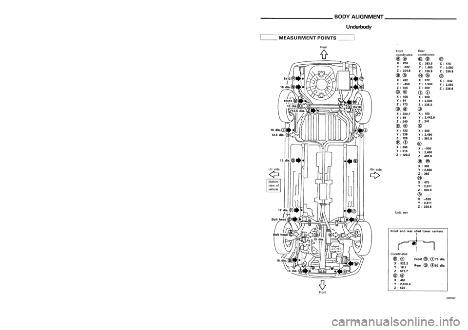
______ HANDLINGPRECAUTIONS FORPLASTICS __
BODYALIGNMENT _
Location OfPlastic Parts
Underbody
Kicking plate(PP)
Front
@,
076
dia.
Rear
@,@
62 dia.
Front
Rear
coordinates: coordinates:
@,@ @,@@
X :250
X:393.5
X:475
V :-632
V:1,460
V:3,082
Z :224.8
Z:126.9
Z:336.8
@,@
(8),
@
@
X :492 X
:572
X:-542
V :-450 V
:1,940
V:3,082
Z :355 Z
:200
Z:336.8
@,@
CD,
CD
X :406
X:600
V :64
V:2,035
Z :172
Z:235.2
@,@
Q)
X :352.7 X
:150
V :69 V
:2,442.9
Z :240 Z
:241
@,
@
@
X :432
X:300
V :338
V:2,480
Z :128
Z:381.8
(f),
CD
@
X :395
X:-300
V :515
V:2,480
Z :129.2
Z:405.8
@,
@)
X :393
Y :2,560
Z :365
@
X :470
Y :2,911
Z :339.6
@
X :-539
Y :2,911
Z :339.6
Unit: mm
Coordinates:
@,0
X :522.2
V :18.1
Z :571.7
@,@ X :465
V :2,456.4
Z :522
Front
andrear strut tower centers
I
~t-~
Rear
(f
••@
LH side
RHside
Q
Q
Bottom
view of
,1
vehicle
__
MEASURMENT POINTS__
Glove box(PPC)
Side
wind molding(PVC)
Cluster lidC(PPC)
Instrument
panel(PPC)
Console box(PPC)
5-door
Hatchback
Cluster lidA(PPC)
~----_/
Front
pillargarnish(PPC)
Side
wind molding(PVC)
Back doorfinisher(ABS)
Roof
spoilar(FRP)
3-doorHatchback
Center pillarlower garnish(PP)
Center pillarupper garnish(PPC)
Rear pillar garnish(PPC)
High
mounted stoplamp
(Lens: PMMA )
Housing: ABS
FrontSBT097
-27-
-18-
Page 202 of 1701
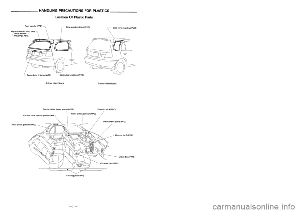
______ HANDLINGPRECAUTIONS FORPLASTICS __
BODYALIGNMENT _
Location OfPlastic Parts
Underbody
Kicking plate(PP)
Front
@,
076
dia.
Rear
@,@
62 dia.
Front
Rear
coordinates: coordinates:
@,@ @,@@
X :250
X:393.5
X:475
V :-632
V:1,460
V:3,082
Z :224.8
Z:126.9
Z:336.8
@,@
(8),
@
@
X :492 X
:572
X:-542
V :-450 V
:1,940
V:3,082
Z :355 Z
:200
Z:336.8
@,@
CD,
CD
X :406
X:600
V :64
V:2,035
Z :172
Z:235.2
@,@
Q)
X :352.7 X
:150
V :69 V
:2,442.9
Z :240 Z
:241
@,
@
@
X :432
X:300
V :338
V:2,480
Z :128
Z:381.8
(f),
CD
@
X :395
X:-300
V :515
V:2,480
Z :129.2
Z:405.8
@,
@)
X :393
Y :2,560
Z :365
@
X :470
Y :2,911
Z :339.6
@
X :-539
Y :2,911
Z :339.6
Unit: mm
Coordinates:
@,0
X :522.2
V :18.1
Z :571.7
@,@ X :465
V :2,456.4
Z :522
Front
andrear strut tower centers
I
~t-~
Rear
(f
••@
LH side
RHside
Q
Q
Bottom
view of
,1
vehicle
__
MEASURMENT POINTS__
Glove box(PPC)
Side
wind molding(PVC)
Cluster lidC(PPC)
Instrument
panel(PPC)
Console box(PPC)
5-door
Hatchback
Cluster lidA(PPC)
~----_/
Front
pillargarnish(PPC)
Side
wind molding(PVC)
Back doorfinisher(ABS)
Roof
spoilar(FRP)
3-doorHatchback
Center pillarlower garnish(PP)
Center pillarupper garnish(PPC)
Rear pillar garnish(PPC)
High
mounted stoplamp
(Lens: PMMA )
Housing: ABS
FrontSBT097
-27-
-18-
Page 233 of 1701
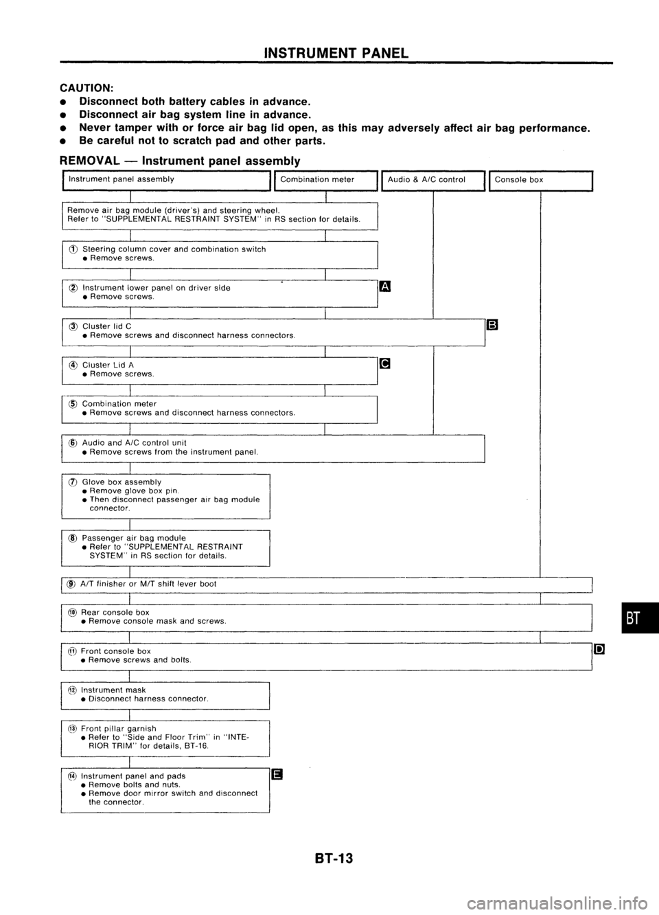
INSTRUMENTPANEL
CAUTION:
• Disconnect bothbattery cablesinadvance.
• Disconnect airbag system lineinadvance.
• Never tamper withorforce airbag lidopen, asthis may adversely affectairbag performance.
• Becareful nottoscratch padandother parts.
REMOVAL -Instrument panelassembly
Instrument panelassembly
Remove airbag module (driver's) andsteering wheel.
Refer to"SUPPLEMENTAL RESTRAINTSYSTEM"inRS section fordetails.
CD
Steering columncoverandcombination switch
• Remove screws.
l6l
Instrument lowerpanel ondriver side
• Remove screws.
@
Cluster lidC
• Remove screwsanddisconnect harnessconnectors. Audio
&AIC
control
Consolebox
@
Cluster lidA
• Remove screws.
@
Combination meter
• Remove screwsanddisconnect harnessconnectors.
cID
Audio and
AIC
control unit
• Remove screwsfromtheinstrument panel.
(J)
Glove boxassembly
• Remove gloveboxpin.
• Then disconnect passengerairbag module
connector.
@
Passenger airbag module
• Refer to"SUPPLEMENTAL RESTRAINT
SYSTEM" inRS section fordetails.
@
AIT
finisher orMIT shift lever boot
@
Rear console box
• Remove consolemaskandscrews.
@
Front console box
• Remove screwsandbolts.
@
Instrument mask
• Disconnect harnessconnector.
@
Front pillargarnish
• Refer to"Side andFloor Trim" in"INTE-
RIOR TRIM" fordetails, 8T-16.
@
Instrument panelandpads
II
• Remove boltsandnuts.
• Remove doormirror switch anddisconnect
the connector.
•
8T-13
Page 393 of 1701

GROUNDDISTRIBUTION
GROUND CONNECT
TO CONN.NO.
CELLCORD
M27 COMBINATION
METER(TACHOMETER) M31EL-METER
COMBINATION METER(AIRBAG WARNING
M'1 RS-SRSEL-WARN
LAMP)
COMBINATION METER(CLOCK ILLUMINA-
M'1 EL-ILL
EL-HORN
TION) (ForEurope andIsrael)
COMBINATION METER(FUELGAUGE) M'1
EL-METER
COMBINATION METER(HIGHBEAM INDICA-
M'1 EL-H/LAMPEL-DTRL
TOR)
COMBINATION METER(SPEEDOMETER) M'1
EC-VSSEC-COOLIF EL-METER
COMBINATION METER(TURN) M'2EL-TURN
COMBINATION METER(WATER TEMP.
M'1 EL-METER
GAUGE)
.
M28/M68
A/T
CONTROL DEVICE(ODCONTROL
(LHD models)
SWITCH) M42
AT-A/T
M28/M60/M68
A/T
CONTROL DEVICE
(A/T
INDICATOR
(RHD models)
ILLUMINATION) M42
EL-ILL
ACCESSORY RELAY(Infuse block) M15
EL-POWER
ASHTRAY ILLUMINATION M44
EL-ILL
BLOWER RELAY(Infuse block) M15
EL-POWER
CIGARETTE LIGHTERSOCKET M43
EL-HORN
COMBINATION FLASHERUNIT M20EL-TURN
COMBINATION METER(METER ILLUMINA- M30
TION) (ForEurope andIsrael) M32EL-ILL
DATA LINKCONNECTOR FORCONSULT M13
EC-MILBR-ABS RS-SRS
DOOR LOCKTIMER (Type-1) M34
EL-D/LOCK
DOOR LOCKTIMER (Type-2) M35EL-D/LOCK
DOOR MIRROR REMOTE CONTROL SWITCHM9 EL-MIRROR
ECM (ENGINE CONTROL MODULE) M39EC-GLOW
FAN SWITCH M45
EC-A/CCUT
EC-LOADHA-A/C
FAN SWITCH ILLUMINATION M48HA-A/C
EL-ILL
FRONT FOGLAMP SWITCH M10EL-F/FOG
EL-ILL
FRONT WIPERAMPLIFIER M74
EL-WIPER
FRONT WIPERMOTOR (WithASS,dualair
M83 EL-WIPER
bag orrear power window)
GLOVE BOXLAMP SWITCH M66EL-ILL
HAZARD SWITCH M54
EL-TURN
EL-ILL
HEADLAMP AIMINGSWITCH M11EL-AIM
HEADLAMP WIPERANDWASHER SWITCH M56 EL-ILL
EL-HLC
IGNITION RELAY(Infuse block) M15EL-POWER
ILLUMINATION CONTROLSWITCH M21
EL-ILL
MIRROR DEFOGGER RELAY M17
EL-DEF
NATS IMMU M36EL-NATS
'1: M30 (With tachometer), M32(Without tachometer)
'2: M30 (Without tachometer), M31(With tachometer)
EL-21
•
Page 487 of 1701
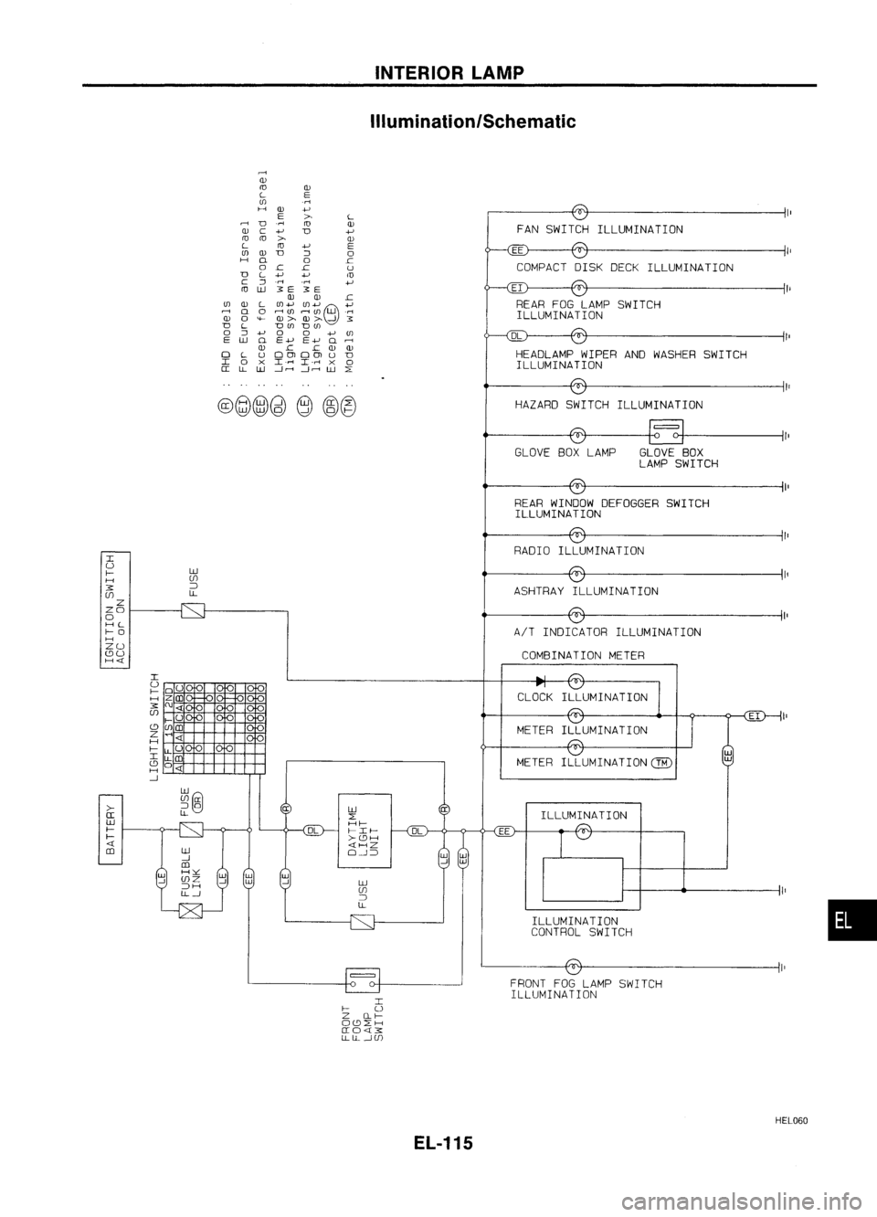
INTERIORLAMP
ilium ination/Schematic
DL
COMPACT
DISKDECK ILLUMINATION
FAN
SWITCH ILLUMINATION
HEADLAMP WIPERANDWASHER SWITCH
ILLUMINA TION
HAZARD SWITCH ILLUMINATION
EI
REAR FOGLAMP SWITCH
ILLUMINA TION
rl
Q)
ro
Q)
L
E
(J)
.rl
H
Q)
+J
E
>
L
D
.rl
ro
Q)
Q)
C
+J
D
+J
ra ra
>
Q)
L
ra
+J
E
(J)
Q)
D
::J
0
H
Q
0
.c
0
.c .c
U
D
L
+J
+J
m
c
::J
.rl
.rl
+J
ro
lLJ
3E
3E
Q) Q)
.c
(J)
Q)
L
(J)+J (J)+J
e
+J
..-;
Q
0
r-l(/)
r-1(J)
W
.rl
Q)
0
'<-
OJ> OJ>
-!
3
D
L
D(J)
D(J)
0
::J
+J
0
0
+J(J)
E
lLJ
Q
E+J E+J
Q..-;
OJ .c
.c
OJ OJ
0
L
UOOlOOlU
D
I
0
X
I.r-l
I-rl
X
0
a:
LL
lLJ
---1.---1
---1.---1
W
L:
@@@)~
e
~@
II
GLOVE BOXLAMP GLOVEBOX
LAMP SWITCH
REAR WINDOW DEFOGGER SWITCH
ILLUMINA TION
CLOCK
•
ILLUMINA
TION
ILLUMINATION
CONTROL SWITCH
METER
FRONT FOGLAMP SWITCH
ILLUMINATION
EE
lLJ
L:
Hf-
I-If-
>-cc:JH
«HZ
O-!~
RADIO
ILLUMINATION
METER
lLJ
UJ
~
LL AIT
INDICATOR ILLUMINATION
ASHTRAY
ILLUMINATION
COMBINATION METER
I
I-
U
Z Ilf-
Occ:JL:H
a:O«3:
LLLL-!UJ
lLJ
UJ
~
LL
>-
a:
lLJ
f-
f-
«
m
I
U
f-
H
3:
UJ
Z
ZO
o
HL
f-O
H
ZU
cc:JU
H«
HEL060
EL-115
Page 492 of 1701
INTERIORLAMP
Illumination/Wiring Diagram-ILL -
(Coni' d)
JUNCTION
BOX NO.2
(JOINT
CONNECTORS)
~:
JOINT
CONNECTOR-4
~:
Next
page
RIG
~ HEADLAMP
~6 WIPER AND
WASHER
SWITCH (ILLUMI-
II 7 II NATION)
L:j='
(856):
B
EL-ILL-05
: LHDmode 1s
:
RHDmodels
Models withdaytime
light system
*9 ...
13
@
3
,
1*.91
RIG
RIG
II!'I
HAZARD
SWITCH
(ILLUMI-
NATION)
~~ B
FUSE
BLOCK
(JIB)
@
IN.BI
RIG
Ii!9TI
~
RIG
t
~o
I
RIG
;2
GLOVE
BOX LAMP
~
l!4Jl
RIW
rn
IN.BI
RIG
I
RIG
REAR WINDOW
i~i
DEFOGGER
SWITCH (ILLUMINA TION)
~ ~
B
Preceding
page
~E -
ILL-02
RIG•
CLOSED GLOVE
BOX LAMP
OPEN SWITCH
~
B BB
LL
m
I1~_I;
JOINT
(
CONNECTOR- 3
_ Next~:
K page JOINT
CONNECTOR-4
---------------------' ~:
~~ ~@
[Q]~
1Irn','1Il~
alll@~
~ W
W
[IIg]
BR54213 W45231 BR
Refer
tolast page
(Foldout page).
rIIII:ITITillTI ~:
rIIII:ITITillTI ~:
~~ ~P
HEL057
EL-120
Page 1485 of 1701
Ventilationairfilter
Evaporator SERVICE
PROCEDURES
Ventilation AirFilter
FUNCTION
Air inside passenger compartment iskept clean ateither recir-
culation orfresh mode byinstalling ventilation airfilter into
cooling unit.
RHA336F REPLACEMENT TIMING
Replace ventilation airfilter every 2years or24,000 km(15,000
miles).
C-aution labelisfixed inside theglove box.
REPLACEMENT PROCEDURES
• Remove gloveboxwhich issecured withtwoclips.
• Remove instrument reinforcement frominstrument panel.
• Cut instrument panelasshown atleft toremove ventilation
air filter.
• Take outventilation airfilter which issecured withoneclip,
from cooling unit.
• Replace withnewoneand reinstall instrument reinforce-
ment oninstrument panel.
• Reinstall glovebox.
•
RHA340F HA-83
Page 1636 of 1701
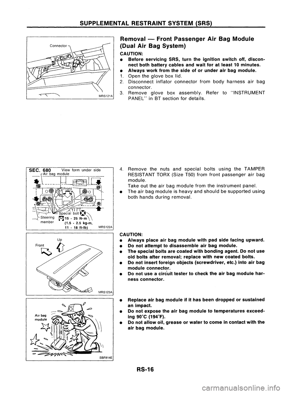
SUPPLEMENTALRESTRAINTSYSTEM(SRS)
Removal -Front Passenger AirBag Module
(Dual AirBag System)
CAUTION:
• Before servicing SRS,turntheignition switchoff,discon-
nect both battery cablesandwait foratleast 10minutes.
• Always workfromtheside ofor under airbag module.
1. Open theglove boxlid.
2. Disconnect inflatorconnector frombody harness airbag
connector.
3. Remove gloveboxassembly. Referto"INSTRUMENT
PANEL" inBT section fordetails.
Air bag
module
4.
Remove thenuts andspecial boltsusing theTAMPER
RESISTANT TORX(SizeT50jfrom front passenger airbag
module.
Take outtheairbag module fromtheinstrument panel.
• The airbag module isheavy andshould besupported using
both hands during removal.
MRS122A
CAUTION:
• Always placeairbag module withpadside facing upward.
• Donot attempt todisassemble airbag module.
• The special boltsarecoated withbonding agent.Donot use
old bolts afterremoval; replacewithnewcoated bolts.
• Donot insert foreign objects (screwdriver, etc.)intoairbag
module connector.
• Donot use acircuit testertocheck theairbag module har-
ness connector.
• Replace airbag module ifithas been dropped orsustained
an impact.
• Donot expose theairbag module totemperatures exceed-
ing 90°C (194°F).
• Donot allow oil,grease orwater tocome incontact withthe
air bag module.
SBF814E RS-16