1995 NISSAN ALMERA N15 CODES
[x] Cancel search: CODESPage 324 of 1701
TROUBLEDIAGNOSES
Self-diagnosis (ForEurope) (ConI'd)
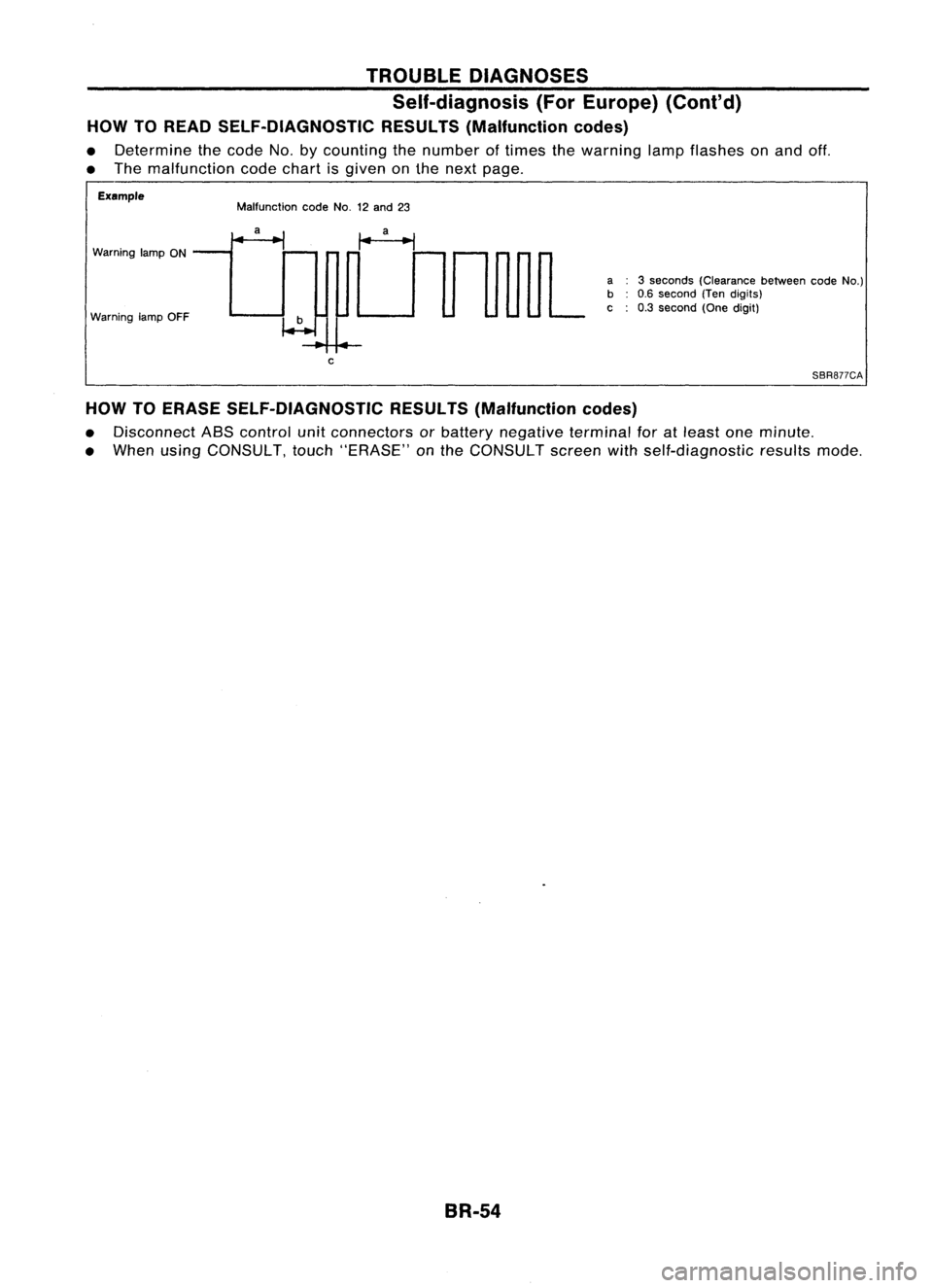
HOW TOREAD SELF-DIAGNOSTIC RESULTS(Malfunction codes)
• Determine thecode No.bycounting thenumber oftimes thewarning lampflashes onand off.
• The malfunction codechart isgiven onthe next page.
Example
Warning lampON
Warning lampOFF Malfunction
codeNo.12and 23
c
a
3seconds (Clearance betweencodeNo.)
b 0.6second (Tendigits)
c 0.3second (Onedigit)
SBR877CA
HOW TOERASE SELF-DIAGNOSTIC RESULTS(Malfunction codes)
• Disconnect ASScontrol unitconnectors orbattery negative terminalforatleast oneminute.
• When usingCONSULT, touch"ERASE" onthe CONSULT screenwithself-diagnostic resultsmode.
BR-54
Page 326 of 1701
TROUBLEDIAGNOSES
Self-diagnosis (ExceptEurope)
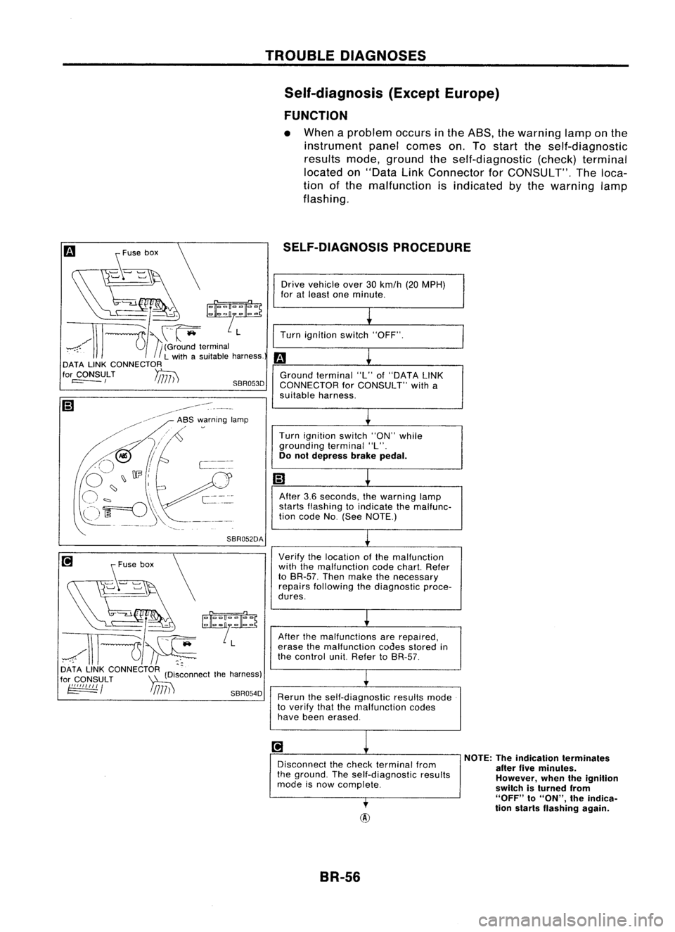
FUNCTION
• When aproblem occursinthe ASS, thewarning lamponthe
instrument panelcomes on.Tostart theself-diagnostic
results mode,ground theself-diagnostic (check)terminal
located on"Data LinkConnector forCONSULT". Theloca-
tion ofthe malfunction isindicated bythe warning lamp
flashing.
SELF-DIAGNOSIS PROCEDURE
[i
s~'~" \
~/''':~~
~/\\l---u~
DATA LINKCONNECTOR (D'.ctthe harness)
for
CONSULT
~Isconne
~ / !
/717) ')
SBR054D
Drive
vehicle over30km/h (20MPH)
for atleast oneminute.
~
Turn ignition switch"OFF".
m
L
Ground terminal "L"of"DATA LINK
CONNECTOR forCONSULT" witha
suitable harness.
L
Turn ignition switch"ON"while
grounding terminal"L".
Do not depress brakepedal.
m
~
After 3.6seconds, thewarning lamp
starts flashing toindicate themalfunc-
tion code No(See NOTE.)
~
Verify thelocation ofthe malfunction
with themalfunction codechart. Refer
to BR-57. Thenmake thenecessary
repairs following thediagnostic proce-
dures.
L
After themalfunctions arerepaired,
erase themalfunction codesstored in
the control unit.Refer toBR-57.
~
Rerun theself-diagnostic resultsmode
to verify thatthemalfunction codes
have been erased.
~
1
Disconnect thecheck terminal from
the ground. Theself-diagnostic results
mode isnow complete.
,
NOTE:
Theindication terminates
after fiveminutes.
However, whentheignition
switch isturned from
"OFF"
to
"ON",
theindica-
tion starts flashing again.
BR-56
Page 327 of 1701
TROUBLEDIAGNOSES
Self-diagnosis (ExceptEurope) (Cont'd)
@
Check warning lampfordeactivation
after driving vehicle over30km/h (20
MPH) foratleast oneminute.
After making certainthatwarning
lamp does notcome on,test theASS
in asafe area toverify thatitfunctions
properly.
•
SBR441C
CODE
NO.32
Tens digits Unitsdigits
Unit: Second
3.6
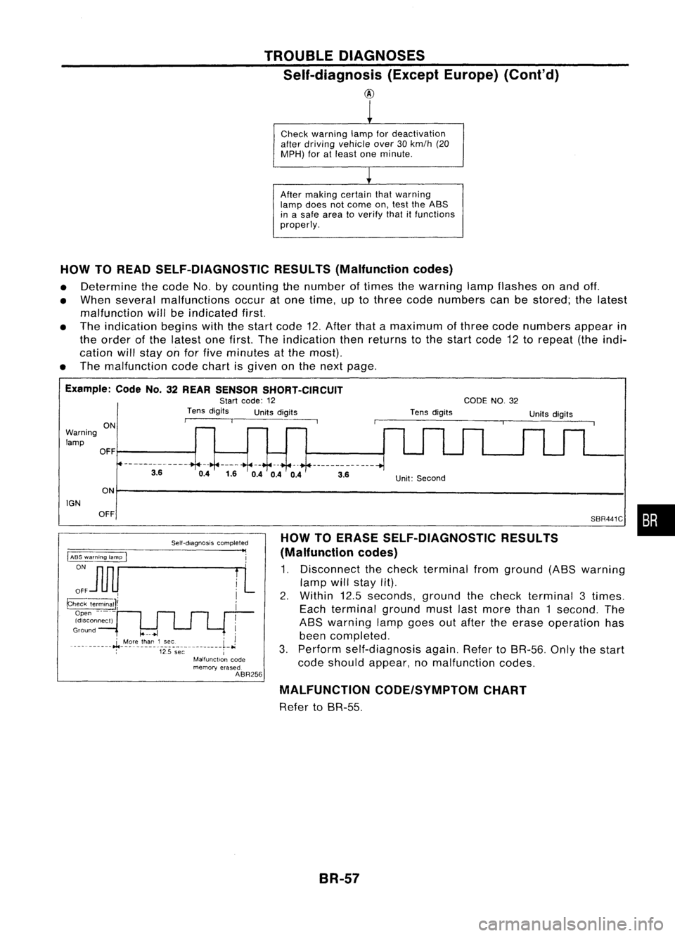
HOW TOERASE SELF-DIAGNOSTIC RESULTS
(Malfunction codes)
1. Disconnect thecheck terminal fromground (ASSwarning
lamp willstay lit).
2. Within 12.5seconds, groundthecheck terminal 3times.
Each terminal groundmustlastmore than1second. The
ASS warning lampgoesoutafter theerase operation has
been completed.
3. Perform self-diagnosis again.RefertoSR-56. Onlythestart
code should appear, nomalfunction codes.
0.4
1.60.40.4 0.4
3.6
ON
OFF
OFF
Self-diagnosiscompleted
"I
~~ i
::J1IU 1
L
p;eck~IJi
i
Open -._.-
Idlsconnect)
!
Ground
10---+1
I
__ .__ ... _--.J..
~9rt'_
!~~_1.~:':. ......L
J
; 12.5
see
j
Malfunction code
memory erased
ABR256
IGN
Warning
lamp ON
HOW
TOREAD SELF-DIAGNOSTIC RESULTS(Malfunction codes)
• Determine thecode No.bycounting thenumber oftimes thewarning lampflashes onand off.
• When several malfunctions occuratone time, uptothree codenumbers canbestored; thelatest
malfunction willbeindicated first.
• The indication beginswiththestart code 12.After thatamaximum ofthree codenumbers appearin
the order ofthe latest onefirst. Theindication thenreturns tothe start code 12torepeat (theindi-
cation willstay onfor five minutes atthe most).
• The malfunction codechart isgiven onthe next page.
Example: CodeNo.32REAR SENSOR SHORT-CIRCUIT
Start code: 12
Tens digits Unitsdigits
MALFUNCTION CODE/SYMPTOM CHART
Refer toSR-55.
BR-57
Page 1355 of 1701
GENERALINFORMATION •
SECTION
G
I
CONTENTS
PRECAUTIONS 2
Supplemental RestraintSystem(SRS)"AIR
BAG" (DualAirBag System) 2
Supplemental RestraintSystem(SRS)"AIR
BAG" (Single AirBag System) 2
Precautions forNATS V2.0(ForGasoline
Engine Model) 3
General Precautions 3
Precautions forMultiport FuelInjection
System orECCS Engine 5
Precautions forThree WayCatalyst 5
Engine Oils 5
Precautions forFuel 6
HOW TOUSE THIS
MANUAL 7
HOW TOREAD WIRING DIAGRAMS 9
Sample/Wiring Diagram-EXAMPL - 9
Description 11
Wiring Diagram Codes(CellCodes) 17
HOW TOPERFORM EFFICIENT DIAGNOSIS FOR
AN ELECTRICAL INCIDENT 18
Work Flow 18
Incident Simulation Tests 19
Circuit Inspection 23
HOW
TOFOLLOW FLOWCHART INTROUBLE
DIAGNOSES 29
CONSULT CHECKING SYSTEM
32
Function andSystem Application 32
Lithium BatteryReplacement.. 32
Checking Equipment 32
IDENTIFICATION INFORMATION 33
Model Variation 33
Identification Number 36
Di mens ions 39
Wheels andTires 39
LIFTING POINTSANDTOW TRUCK TOWING ..40
Preparation 40
Board-on
Lift
40
Garage JackandSafety Stand 41
2-pole Lift 42
Tow Truck Towing 43
TIGHTENING TORQUEOFSTANDARD BOLTS
44
SAE J1930 TERMINOLOGY LIST 45
SAE J1930 Terminology List.. 45
Page 1366 of 1701
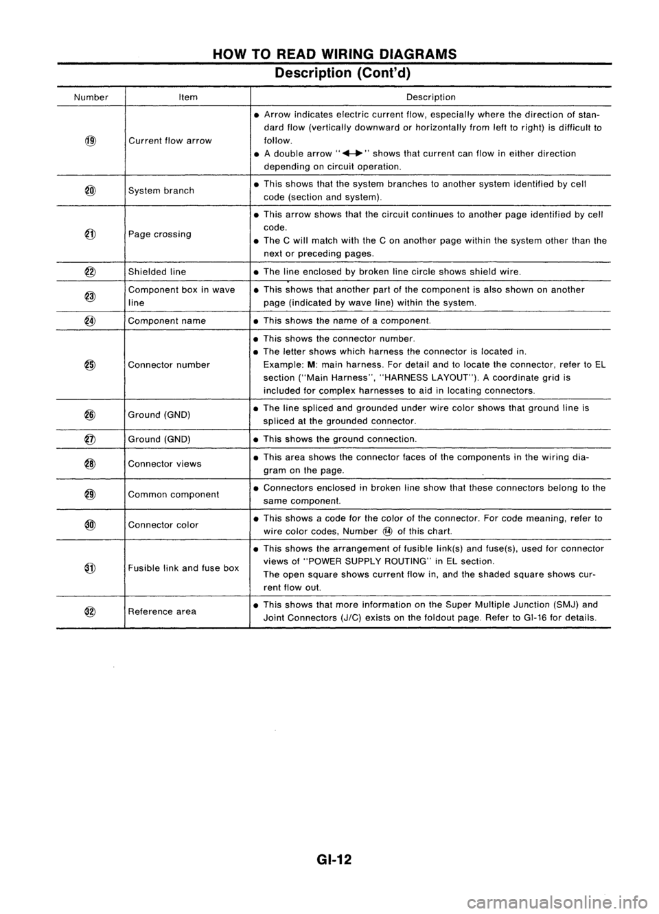
HOWTOREAD WIRING DIAGRAMS
Description (Cont'd)
Number Item Description
• Arrow indicates electriccurrentflow,especially wherethedirection ofstan-
dard flow(vertically downward orhorizontally fromlefttoright) isdifficult to
@)
Current
flowarrow follow.
• Adouble arrow" ...."shows thatcurrent canflow ineither direction
depending oncircuit operation .
@)
System
branch •
This shows thatthesystem branches toanother systemidentified bycell
code (section andsystem) .
• This arrow shows thatthecircuit continues toanother pageidentified bycell
@
code.
Page crossing
•The Cwill match withtheCon another pagewithin thesystem otherthanthe
next orpreceding pages.
@
Shieldedline •
The lineenclosed bybroken linecircle shows shieldwire.
@)
Component
boxinwave •
This shows thatanother partofthe component isalso shown onanother
line page
(indicated bywave line)within thesystem.
@
Component
name •This shows thename ofacomponent.
• This shows theconnector number.
• The letter shows whichharness theconnector islocated in.
@)
Connector
number Example:
M:main harness. Fordetail andtolocate theconnector, refertoEL
section ("MainHarness", "HARNESS LAYOUT").Acoordinate gridis
included forcomplex harnesses toaid inlocating connectors .
@
Ground
(GND) •
The linespliced andgrounded underwirecolor shows thatground lineis
spliced atthe grounded connector.
@
Ground
(GND) •
This shows theground connection.
@)
Connector
views •
This area shows theconnector facesofthe components inthe wiring dia-
gram onthe page .
@)
Common
component •
Connectors enclosedinbroken lineshow thatthese connectors belongtothe
same component.
@l
Connector
color •
This shows acode forthe color ofthe connector. Forcode meaning, referto
wire color codes, Number
@
ofthis chart.
• This shows thearrangement offusible link(s)andfuse(s), usedforconnector
@
views
of"POWER SUPPLYROUTING" inEL section.
Fusible linkand fuse box
Theopen square showscurrent flowin,and theshaded squareshowscur-
rent flow out.
@
Reference
area •
This shows thatmore information onthe Super Multiple Junction (SMJ)and
Joint Connectors
(J/C)
exists onthe foldout page.RefertoGI-16 fordetails.
GI-12
Page 1371 of 1701
HOWTOREAD WIRING DIAGRAMS
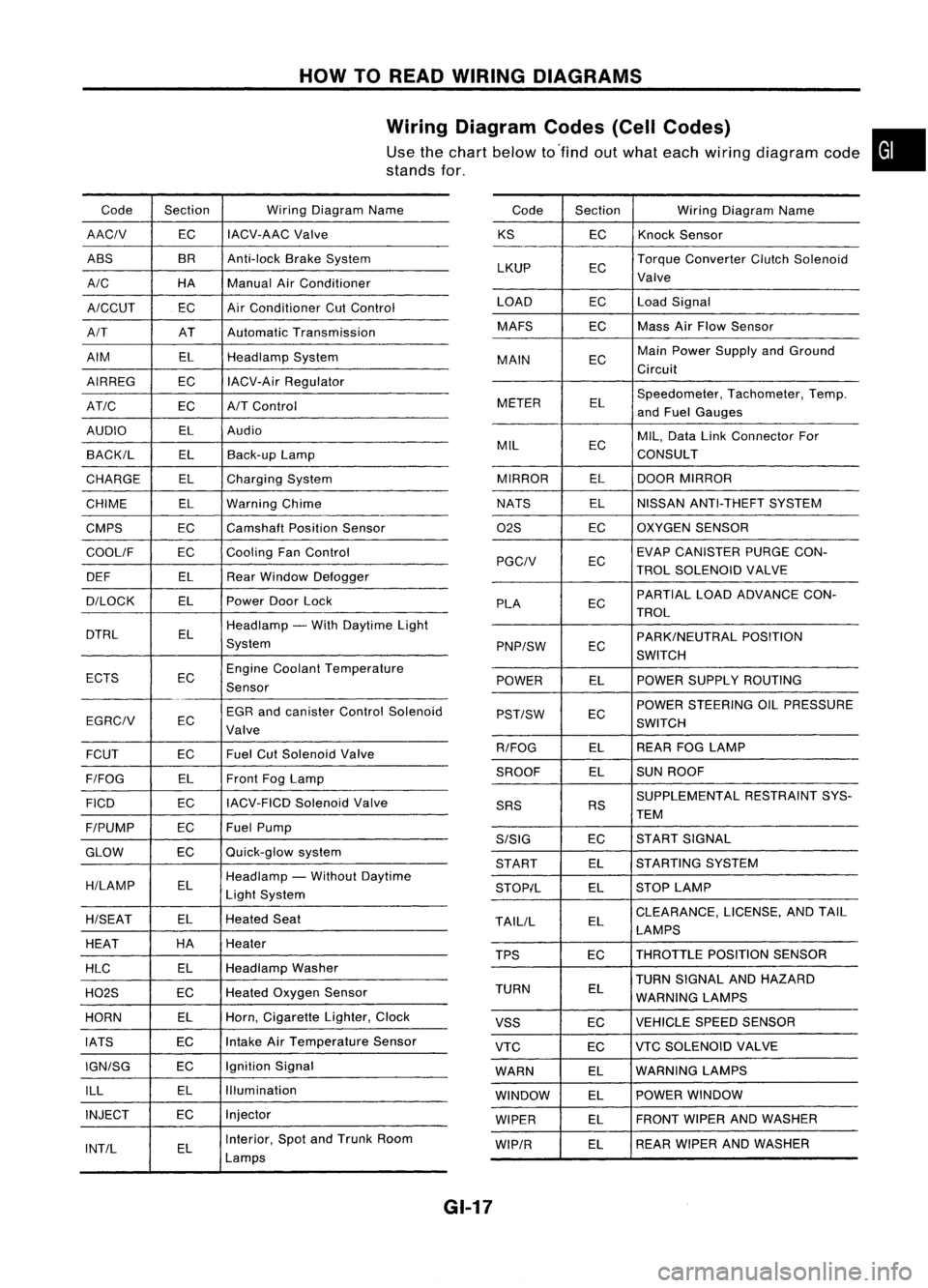
Wiring Diagram Codes(CellCodes)
Use thechart below to'find outwhat each wiring diagram code•
stands for,
Code Section WiringDiagram Name
AACIV ECIACV-AAC
Valve
ABS BR
Anti-lock BrakeSystem
A/C HAManualAirConditioner
A/CCUT ECAir
Conditioner CutControl
A/T ATAutomatic Transmission
AIM ELHeadlamp System
AIRREG ECIACV-Air Regulator
AT/C ECA/TControl
AUDIO ELAudio
BACK/L ELBack-up Lamp
CHARGE ELCharging System
CHIME ELWarning Chime
CMPS EC
Camshaft PositionSensor
COOllF ECCooling
FanControl
DEF ELRearWindow Defogger
D/LOCK ELPowerDoorLock
DTRL ELHeadlamp
-With Daytime Light
System
ECTS ECEngine
Coolant Temperature
Sensor
EGR andcanister ControlSolenoid
EGRCIV EC
Valve
FCUT ECFuel
CutSolenoid Valve
F/FOG ELFront
FogLamp
FICO ECIACV-FICD
SolenoidValve
F/PUMP ECFuel
Pump
GLOW ECQuick-glow
system
H/LAMP ELHeadlamp
-Without Daytime
Light System
H/SEAT ELHeated
Seat
HEAT HA
Heater
HLC ELHeadlamp
Washer
H02S ECHeated
Oxygen Sensor
HORN ELHorn,
Cigarette Lighter,Clock
IATS ECIntake
AirTemperature Sensor
IGN/SG ECIgnition
Signal
ILL ELIllumination
INJECT ECInjector
INT/L ELInterior,
SpotandTrunk Room
Lamps Code
Section WiringDiagram Name
KS ECKnock
Sensor
LKUP ECTorque
Converter ClutchSolenoid
Valve
LOAD ECLoadSignal
MAFS ECMass
AirFlow Sensor
MAIN ECMain
Power Supply andGround
Circuit
METER ELSpeedometer,
Tachometer,Temp.
and Fuel Gauges
MIL ECMIL,
Data LinkConnector For
CONSULT
MIRROR ELDOOR
MIRROR
NATS ELNISSAN
ANTI-THEFT SYSTEM
02S ECOXYGEN
SENSOR
EC EVAP
CANISTER PURGECON-
PGCIV TROLSOLENOID VALVE
PLA ECPARTIAL
LOADADVANCE CON-
TROL
EC PARK/NEUTRAL
POSITION
PNP/SW SWITCH
POWER ELPOWER
SUPPLY ROUTING
POWER STEERING OILPRESSURE
PST/SW EC
SWITCH
R/FOG ELREAR
FOGLAMP
SROOF ELSUN
ROOF
SUPPLEMENTAL RESTRAINTSYS-
SRS RS
TEM
S/SIG ECST
ART SIGNAL
START ELSTARTING
SYSTEM
STOP/L ELSTOP
LAMP
TAllIL ELCLEARANCE,
LICENSE,ANDTAIL
LAMPS
TPS ECTHROTTLE
POSITIONSENSOR
TURN SIGNAL ANDHAZARD
TURN EL
WARNING LAMPS
VSS ECVEHICLE
SPEEDSENSOR
VTC ECVTC
SOLENOID VALVE
WARN ELWARNING
LAMPS
WINDOW ELPOWER
WINDOW
WIPER ELFRONT
WIPERANDWASHER
WIP/R ELREAR
WIPER ANDWASHER
GI-17
Page 1653 of 1701
TROUBLEDIAGNOSES -Supplemental RestraintSystem(SRS)-
Dual AirBag System
Self-diagnosis (Cont'd)
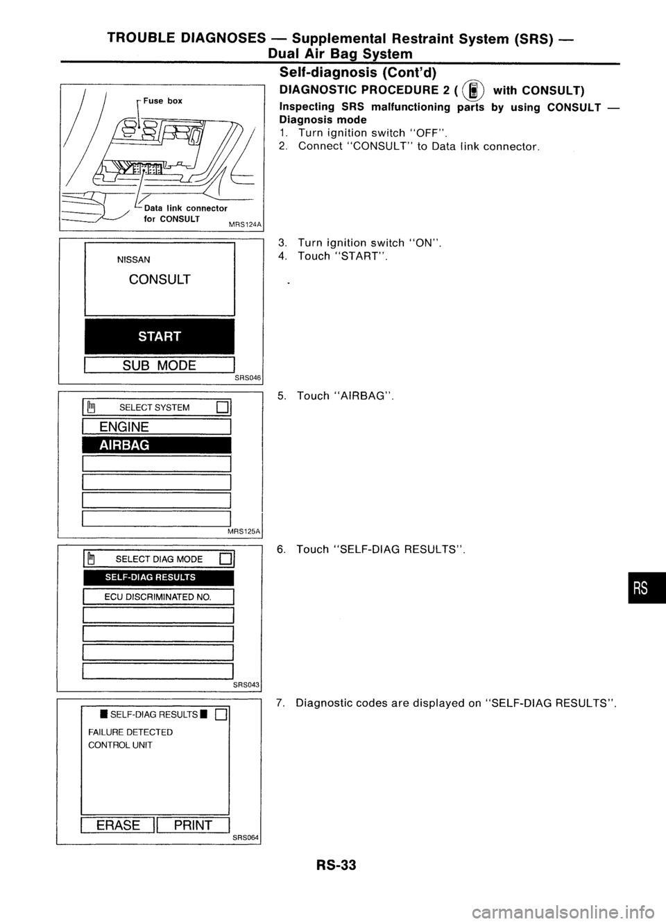
DIAGNOSTIC PROCEDURE2
(00
withCONSULT)
Inspecting SRSmalfunctioning partsbyusing CONSULT -
Diagnosis mode
1. Turn ignition switch"OFF".
2. Connect "CONSULT" toData linkconnector.
MRS124A
AIRBAG SELF-DIAG RESULTS
NISSAN
CONSULT
START
SUB MODE
I
SRS046
I ~
SELECT SYSTEM
01
I
ENGINE
1
1 '
1-----1
I
I
I 1
MRS125A
I ~
SELECT DIAGMODE
01
I
ECUDISCRIMINATED NO.
I
'======
1 -
1 -
1========
SRS043
• SELF-DIAG RESULTS.
0
FAILURE DETECTED
CONTROL UNIT
I
ERASE
II
PRINT
I
SRS064
3.
Turn ignition switch"ON".
4. Touch "START".
5. Touch "AIRBAG".
6. Touch "SELF-DIAG RESULTS".
7. Diagnostic codesaredisplayed on"SELF-DIAG RESULTS".
RS-33
•
Page 1654 of 1701
•SELF-DIAG RESULTS.
0
FAILURE DETECTED
• NO SELF DIAGNOSTIC
FAILURE INDICATED.
TROUBLE
DIAGNOSES -Supplemental RestraintSystem(SRS)-
Dual AirBag System
Self-diagnosis (Cont'd)
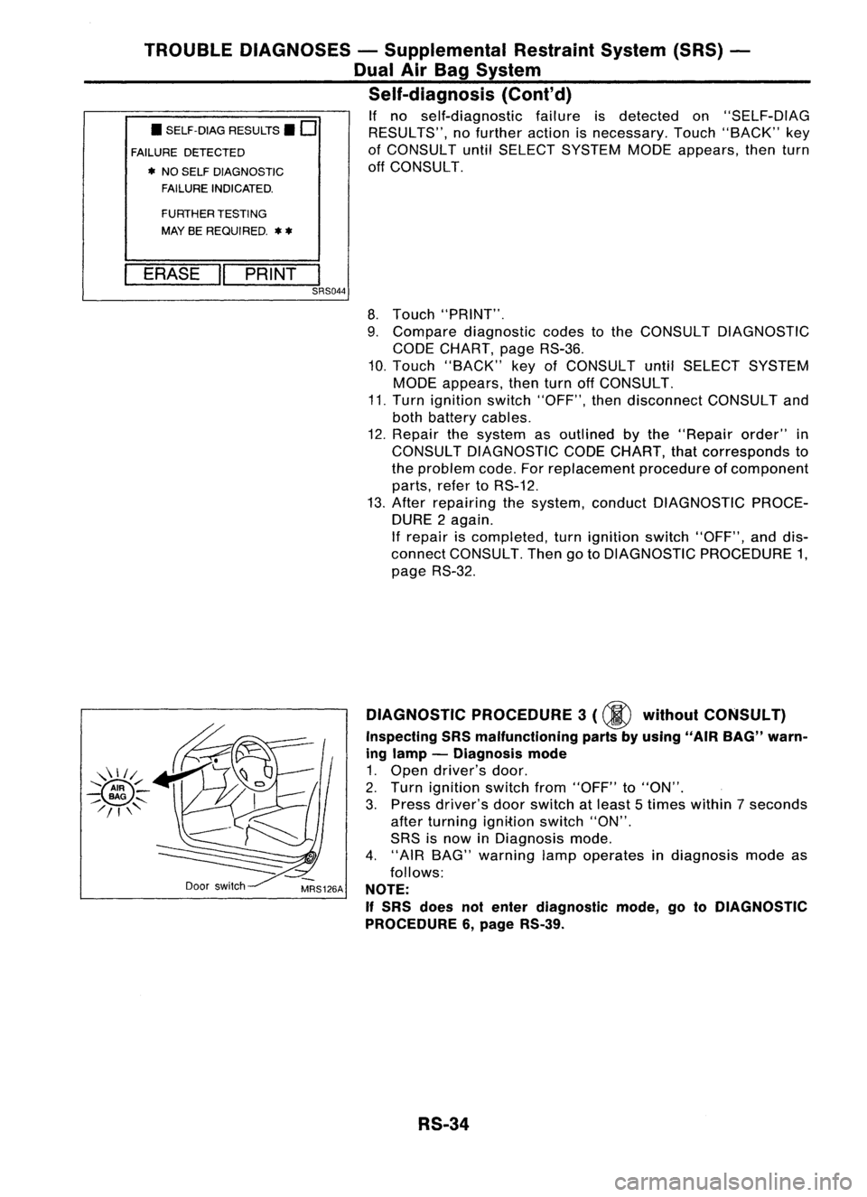
If no self-diagnostic failureisdetected on"SELF-DIAG
RESULTS", nofurther actionisnecessary. Touch"BACK" key
of CONSULT untilSELECT SYSTEM MODEappears, thenturn
off CONSULT.
FURTHER TESTING
MAY BEREQUIRED.
**
ERASE "PRINT
I
SRS044
8.Touch "PRINT".
9. Compare diagnostic codestothe CONSULT DIAGNOSTIC
CODE CHART, pageRS-36.
10. Touch "BACK" keyofCONSULT untilSELECT SYSTEM
MODE appears, thenturnoffCONSULT.
11. Turn ignition switch"OFF", thendisconnect CONSULTand
both battery cables.
12. Repair thesystem asoutlined bythe "Repair order"in
CONSULT DIAGNOSTIC CODECHART, thatcorresponds to
the problem code.Forreplacement procedureofcomponent
parts, refertoRS-12.
13. After repairing thesystem, conduct DIAGNOSTIC PROCE-
DURE 2again.
If repair iscompleted, turnignition switch"OFF", anddis-
connect CONSULT. ThengotoDIAGNOSTIC PROCEDURE 1,
page RS-32.
Door switch DIAGNOSTIC
PROCEDURE 3
(00
without CONSULT)
Inspecting SRSmalfunctioning partsbyusing "AIRBAG" warn-
ing lamp -Diagnosis mode
1. Open driver's door.
2. Turn ignition switchfrom"OFF" to"ON".
3. Press driver's doorswitch atleast 5times within 7seconds
after turning ignition switch"ON".
SRS isnow inDiagnosis mode.
4. "AIR BAG" warning lampoperates indiagnosis modeas
follows:
NOTE:
If
SRS does notenter diagnostic mode,gotoDIAGNOSTIC
PROCEDURE 6,page RS-39.
RS-34