1995 NISSAN ALMERA N15 door locks
[x] Cancel search: door locksPage 229 of 1701
BODYEND
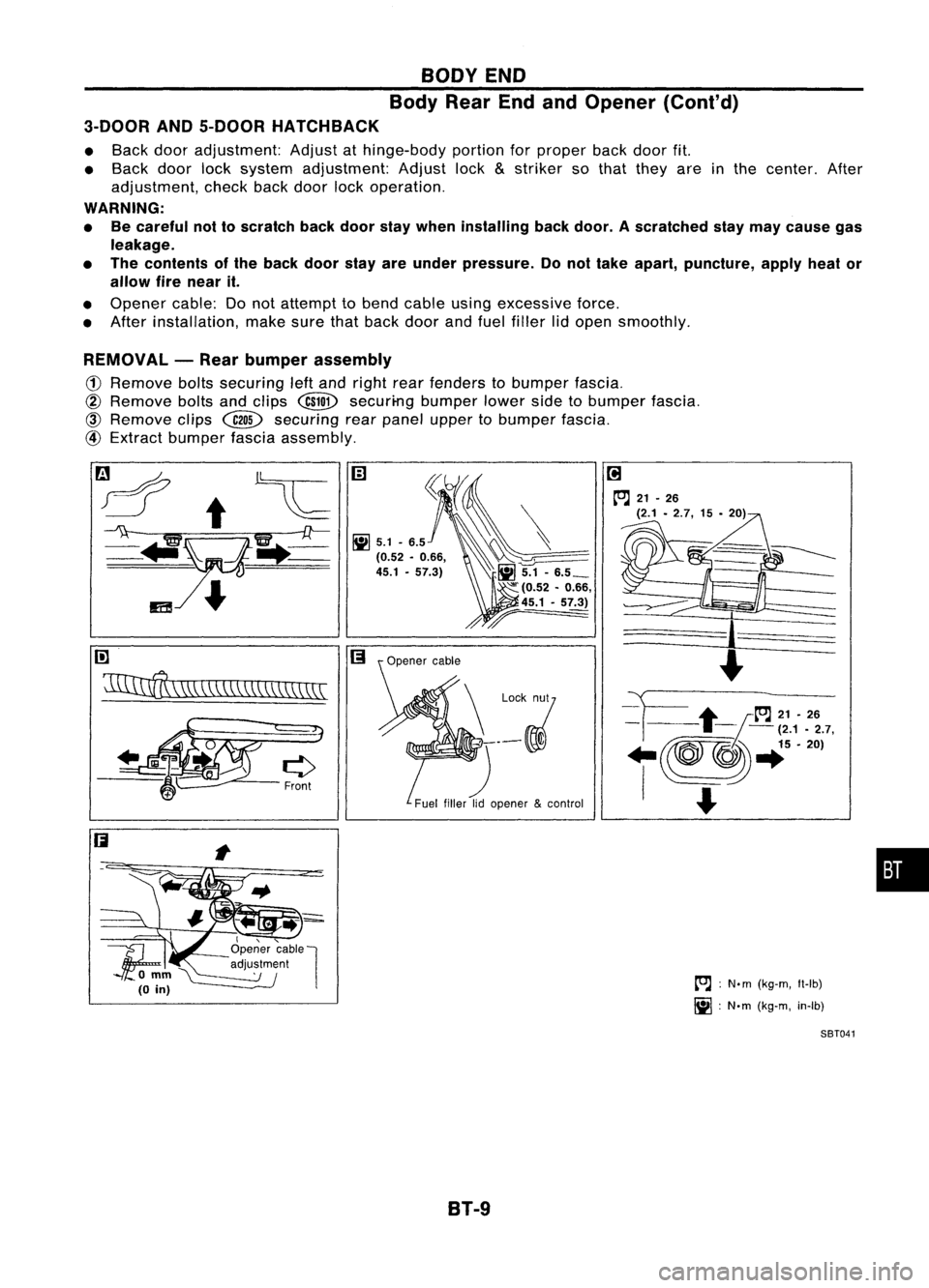
Body RearEndandOpener (Cont'd)
3-DOOR AND5-DOOR HATCHBACK
• Back dooradjustment: Adjustathinge-body portionforproper backdoorfit.
• Back doorlocksystem adjustment: Adjustlock
&
striker sothat they areinthe center. After
adjustment, checkbackdoor lockoperation.
WARNING:
• Becareful nottoscratch backdoor staywhen installing backdoor. Ascratched staymay cause gas
leakage.
• The contents ofthe back doorstayareunder pressure. Donot take apart, puncture, applyheator
allow firenear it.
• Opener cable:Donot attempt tobend cable usingexcessive force.
• After installation, makesurethatback doorandfuel filler lidopen smoothly.
REMOVAL -Rear bumper assembly
(1)
Remove boltssecuring leftand right rearfenders tobumper fascia.
@
Remove boltsandclips
@ill>
securi-ng bumperlowersidetobumper fascia.
@)
Remove clips~ securing rearpanel upper tobumper fascia.
@
Extract bumper fasciaassembly.
rn
~\\\\\\\\\\\\\\\\\\\\\\
I,"-
1f;
Openercable
l
'\ '--- adju~~m~nl
omm~
(0
in)
B1-9
[O.J
:
N.m (kg-m, Il-Ib)
~ :N'm (kg-m, in-Ib)
SBT041
•
Page 570 of 1701
POWERDOORLOCK
System Description
NISSAN modelN15hastwotypes ofpower doorlocksystem:
• Type 1:For Europe andAustralia
• Type 2:Except forEurope andAustralia
Power issupplied atall times
• through 25Afusible link(letter
OJ,
located inthe fusible linkand fuse box)
• tocircuit breaker terminal
(!)
• through circuitbreaker terminal
@
• todoor locktimer terminal
@
(Type-1) or
CID
(Type-2).
Ground issupplied todoor locktimer terminal
@
(Type-1) or
(!)
(Type-2) throughbodygrounds @D,
@ID
and
@D.
POWER DOORLOCKOPERATION
When oneofthe following inputsignals issupplied:
• driver sidedoor islocked/unlocked usingkeyorlock knob,
• passenger sidedoor islocked/unlocked usingkeyorlock knob (Only fortype-1);
• door lock
&
unlock switchinthe power window mainswitch islocked/unlocked (OnlyforRHD mod-
els type-2)
Door locktimer locks/unlocks driversidedoor (Only fortype-1) andother doors.
Input (Type-1)
Unlock signal
When thedriver sidedoor isunlocked usingkeyorlock knob, ground issupplied
• todoor locktimer terminal
@
• through driversidedoor lockactuator (doorunlock sensor) terminal
@
• todriver sidedoor lockactuator (doorunlock sensor) terminal
@
• through bodygrounds @D,
@ID
and
@D.
When thepassenger sidedoor isunlocked usingkeyorlock knob, ground issupplied
• todoor locktimer terminal
CID
• through passenger sidedoor lockactuator (doorunlock sensor) terminal
@
• topassenger sidedoor lockactuator (doorunlock sensor) terminal
@
• through bodygrounds @D,
@ID
and@D.
Lock signal
The door locktimer terminal
@
or
@
receives locksignal whentheunlock signalisshut off.
Input (Type-2)
When thelock knob switch isin UNLOCKED position,groundissupplied
• todoor locktimer terminal
CID
• through lockknob switch terminal
@
• tolock knob switch terminal
(!)
• through bodygrounds @D,
@ID
and
@ill.
The door locktimer terminal
CID
receives locksignal whentheunlock signalisshut off.
Input (Only forRHO models type-2)
When thedoor lock
&
unlock switch inthe power window mainswitch isin LOCKED position,groundis
supplied
• todoor locktimer terminal
CID
• through doorlock
&
unlock switchinthe power window mainswitch terminal
@
• todoor lock
&
unlock switch inthe power window mainswitch terminal
CID
• through bodygrounds @D,
@@
and
@ill.
When thedoor lock
&
unlock switchinthe power window mainswitch isin UNLOCKED position,ground
is supplied
• todoor locktimer terminal
@
• through doorlock
&
unlock switchinthe power window mainswitch terminal
(J)
• todoor lock
&
unlock switchinthe power window mainswitch terminal
CID
• through bodygrounds @D,
@@
and
@ill.
EL-198
Page 582 of 1701
POWERDOORLOCK
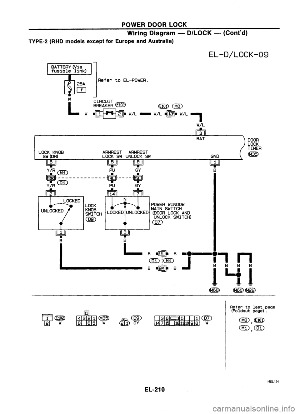
Wiring Diagram -D/LOCK -(Cont'd)
TVPE-2 (RHOmodels exceptforEurope andAustralia)
EL-D/LOCK-09
Refer toEL-POWER.
CIRCUIT
BREAKER
(E102) (E101)
CHID
~ W/L- W/L~ W/L,
W!L
m
BAT
LOCK KNOB ARMRESTARMREST
SW(DR) LOCKSWUNLOCK SW
~ ~~
Y/R
CMD
PUGY
I~~-------------~~~----~~I
Y/R
(]I)
PUGY
m
IIT4il
m
GND
Ibi=H
B
DOOR
LOCK
TIMER
@
B
Iff@-
B._---.,
n
(]I):CMD
J
nmL
BB BB
B~B
Il..il
~ ~~
~
B
L
POWER
WINDOW
MAIN SWITCH
LOCKED UNLOCKED (DOORLOCKAND
UNLOCK SWITCH)
(]I)
LOCK
KNOB
SWITCH
@)
LOCKED
Refertolast page
(Foldout page).
HEL124
EL-210
Page 590 of 1701
![NISSAN ALMERA N15 1995 Service Manual
m
~i5
Door locktimer
connector
@
B
B
PU
tGY
II][]
I
SEL462U
I!J
~i5
Door lock&unlock
switch connector
@
~
~71
I
I
I
I
I
J
CEL059-A POWER
DOORLOCK
Trouble Diagnoses -Type 2(Except NISSAN ALMERA N15 1995 Service Manual
m
~i5
Door locktimer
connector
@
B
B
PU
tGY
II][]
I
SEL462U
I!J
~i5
Door lock&unlock
switch connector
@
~
~71
I
I
I
I
I
J
CEL059-A POWER
DOORLOCK
Trouble Diagnoses -Type 2(Except](/manual-img/5/57349/w960_57349-589.png)
m
~i5
Door locktimer
connector
@
B
B
PU
tGY
II][]
I
SEL462U
I!J
~i5
Door lock&unlock
switch connector
@
~
~71
I
I
I
I
I
J
CEL059-A POWER
DOORLOCK
Trouble Diagnoses -Type 2(Except forEurope
and Australia) (Cont'd)
PROCEDURE 2
(Door lock
&
unlock switchcheck)
m
DOOR LOCK
&
UNLOCK SWITCHSIG-OK
Doorlock
&
unlock
NAL CHECK
---...
switchisOK.
Measure voltagebetween doorlock
timer harness terminals
CID
and Q).
@ and Q).
Condition
Terminals ofdoor
lock
&
Voltage
unlock [V]
EB
e
switch
12
@
d)
Unlock Approx.
12
NG
m
DOOR LOCK
&
UNLOCK SWITCH NG
Replace doorlock
&
CHECK ~
unlockswitch.
Check continuity betweendoorlock
&
unlock switchterminals
(J)
and
@.@
and
@.
Conditionof
Terminals doorlock
&
Continuity
unlock switch
(f)
and @
Lock Yes
@ and @ Unlock Yes
OK
Check thefollowing.
1) Harness betweendoorlocktimer
and door lock
&
unlock switchfor
open/short circuit
2) Door lock
&
unlock switch ground
circuit
EL-218
Page 1491 of 1701
PRE-DELIVERYINSPECTIONITEMS
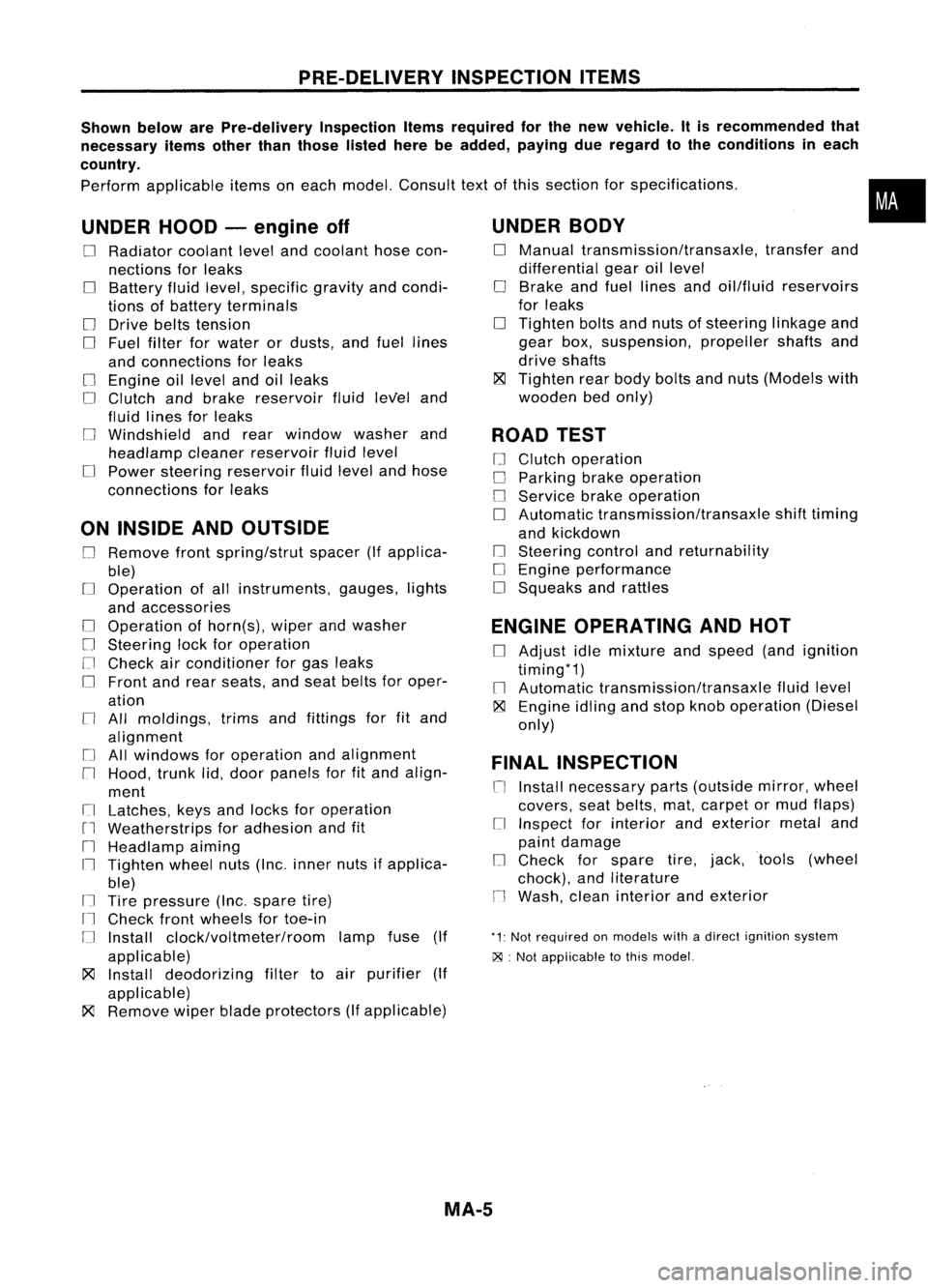
Shown belowarePre-delivery InspectionItemsrequired forthe new vehicle. Itis recommended that
necessary itemsotherthanthose listedherebeadded, payingdueregard tothe conditions ineach
country.
Perform applicable itemsoneach model. Consult textofthis section forspecifications .
UNDER HOOD-engine off
o
Radiator coolantlevelandcoolant hosecon-
nections forleaks
o
Battery fluidlevel, specific gravityandcondi-
tions ofbattery terminals
o
Drive beltstension
D
Fuel filter forwater ordusts, andfuel lines
and connections forleaks
[] Engine oillevel andoilleaks
D
Clutch andbrake reservoir fluidlevel and
fluid lines forleaks
o
Windshield andrear window washerand
headlamp cleanerreservoir fluidlevel
D
Power steering reservoir fluidlevel andhose
connections forleaks
ON INSIDE ANDOUTSIDE
D
Remove frontspring/strut spacer(Ifapplica-
ble)
D
Operation ofall instruments, gauges,lights
and accessories
o
Operation ofhorn(s), wiperandwasher
[] Steering lockforoperation
[] Check airconditioner forgas leaks
o
Front andrear seats, andseat belts foroper-
ation
n
All moldings, trimsandfittings forfitand
alignment
[J
Allwindows foroperation andalignment
n
Hood, trunklid,door panels forfitand align-
ment
[1
Latches, keysandlocks foroperation
rl
Weatherstrips foradhesion andfit
[l
Headlamp aiming
I~ Tighten wheelnuts(Inc. inner nutsifapplica-
ble)
IJ Tire pressure (Inc.spare tire)
Il
Check frontwheels fortoe-in
IJ Install clock/voltmeter/room lampfuse(If
applicable)
~ Install deodorizing filtertoair purifier (If
applicable)
~ Remove wiperbladeprotectors (Ifapplicable)
UNDER
BODY
o
Manual transmission/transaxle, transferand
differential gearoillevel
D
Brake andfuel lines andoil/fluid reservoirs
for leaks
D
Tighten boltsandnuts ofsteering linkageand
gear box,suspension, propellershaftsand
drive shafts
~ Tighten rearbody boltsandnuts (Models with
wooden bedonly)
ROAD TEST
D
Clutch operation
D
Parking brakeoperation
[J
Service brakeoperation
D
Automatic transmission/transaxle shifttiming
and kickdown
[] Steering controlandreturnability
o
Engine performance
D
Squeaks andrattles
ENGINE OPERATING ANDHOT
D
Adjust idlemixture andspeed (andignition
timing*1)
n
Automatic transmission/transaxle fluidlevel
~ Engine idlingandstop knob operation (Diesel
only)
FINAL INSPECTION
n
Install necessary parts(outside mirror,wheel
covers, seatbelts, mat,carpet ormud flaps)
[1
Inspect forinterior andexterior metaland
paint damage
[] Check forspare tire,jack, tools (wheel
chock), andliterature
n
Wash, cleaninterior andexterior
"1: Not required onmodels withadirect ignition system
~ :Not appiicable tothis model.
•
MA-5
Page 1492 of 1701
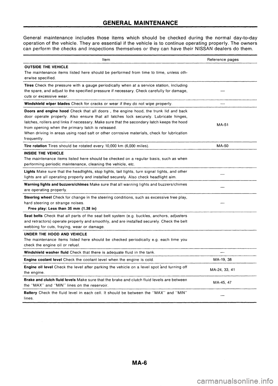
GENERALMAINTENANCE
General maintenance includesthoseitemswhich should bechecked duringthenormal day-to-day
operation ofthe vehicle. Theyareessential ifthe vehicle isto continue operating properly.Theowners
can perform thechecks andinspections themselves orthey canhave theirNISSAN dealersdothem.
Item
OUTSIDE THEVEHICLE
The maintenance itemslistedhereshould beperformed fromtimetotime, unless oth-
erwise specified.
Tires
Check thepressure withagauge periodically whenataservice station, including
the spare, andadjust tothe specified pressureifnecessary. Checkcarefully fordamage,
cuts orexcessive wear.
Windshield wiperblades
Checkforcracks orwear ifthey donot wipe properly.
Doors andengine hood
Check thatalldoors, theengine hood,thetrunk lidand back
door operate properly. Alsoensure thatalllatches locksecurely. Lubricate hinges,
latches, rollersandlinks ifnecessary. Makesurethatthesecondary latchkeeps thehood
from opening whentheprimary latchisreleased.
When driving inareas usingroadsaltorother corrosive materials, checkforlubrication
frequently.
Tire rotation
Tiresshould berotated every
10,000
km
(6,000
miles).
INSIDE THEVEHICLE
The maintenance itemslistedhereshould bechecked onaregular basis,suchaswhen
performing periodicmaintenance, cleaningthevehicle, etc.
Lights
Makesurethattheheadlights, stoplights, taillights, turnsignal lights,andother
lights arealloperating properlyandinstalled securely. Alsocheck headlight aim.
Warning lightsandbuzzers/chimes
Makesurethatallwarning lightsandbuzzers/chimes
are operating properly.
Steering wheel
Check forchange inthe steering conditions, suchasexcessive freeplay,
hard steering orstrange noises.
Free play: Lessthan35mm (1.38 in)
Seat belts
Check thatallparts ofthe seat beltsystem (e.g.buckles, anchors, adjusters
and retractors) operateproperly andsmoothly, andareinstalled securely. Checkthebelt
webbing forcuts, fraying, wearordamage.
UNDER THEHOOD ANDVEHICLE
The maintenance itemslisted hereshould bechecked periodically e.g.each timeyou
check theengine oilorrefuel.
Windshield washerfluid
Check thatthere isadequate fluidinthe tank.
Engine coolant level
Check thecoolant levelwhen theengine iscold.
Engine oillevel
Check thelevel afterparking thevehicle onalevel spotandturning off
the engine.
Brake andclutch fluidlevels
Makesurethatthebrake andclutch fluidlevels arebetween
the "MAX" and"MIN" linesonthe reservoir.
Battery
Checkthefluid level ineach cell.Itshould bebetween the"MAX" and"MIN"
lines.
MA-6
Reference
pages
MA-51
MA-50
MA-19,38
MA-24, 33,41
MA-45,47
Page 1639 of 1701
SUPPLEMENTALRESTRAINTSYSTEM(SRS)
Disposal ofAir Bag Module andSeat Belt
Pre-tensioner
• Before disposing ofair bag module andseat beltpre-tensioner, orvehicles equipped withsuch
systems, deploythesystems. Ifsuch systems havealready beendeployed duetoan accident, dis-
pose ofas indicated in"DISPOSING OFAIR BAG MODULE ANDSEAT BELTPRE-TENSIONER" (RS-
24).
• When deploying theairbag module, alwaysusetheSpecial Service Tool;Deployment tool
KV99106400.
• When deploying theairbag module andseat beltpre-tensioner, standatleast 5m (16 ft)away from
the deployment component.
• Due toheat, leave airbag module unattended formore than30minutes afterdeployment. Alsoleave
seat beltpre-tensioner unattendedformore than10minutes afterdeployment.
• Besure towear gloves whenhandling adeployed airbag module andseat beltpre-tensioner.
• Never applywater toadeployed airbag module.
• Wash yourhands cleanafterfinishing- work.
• Donot dispose ofthe airbag module andseat beltpre-tensioner un-deployed.
CHECKING DEPLOYMENT TOOL
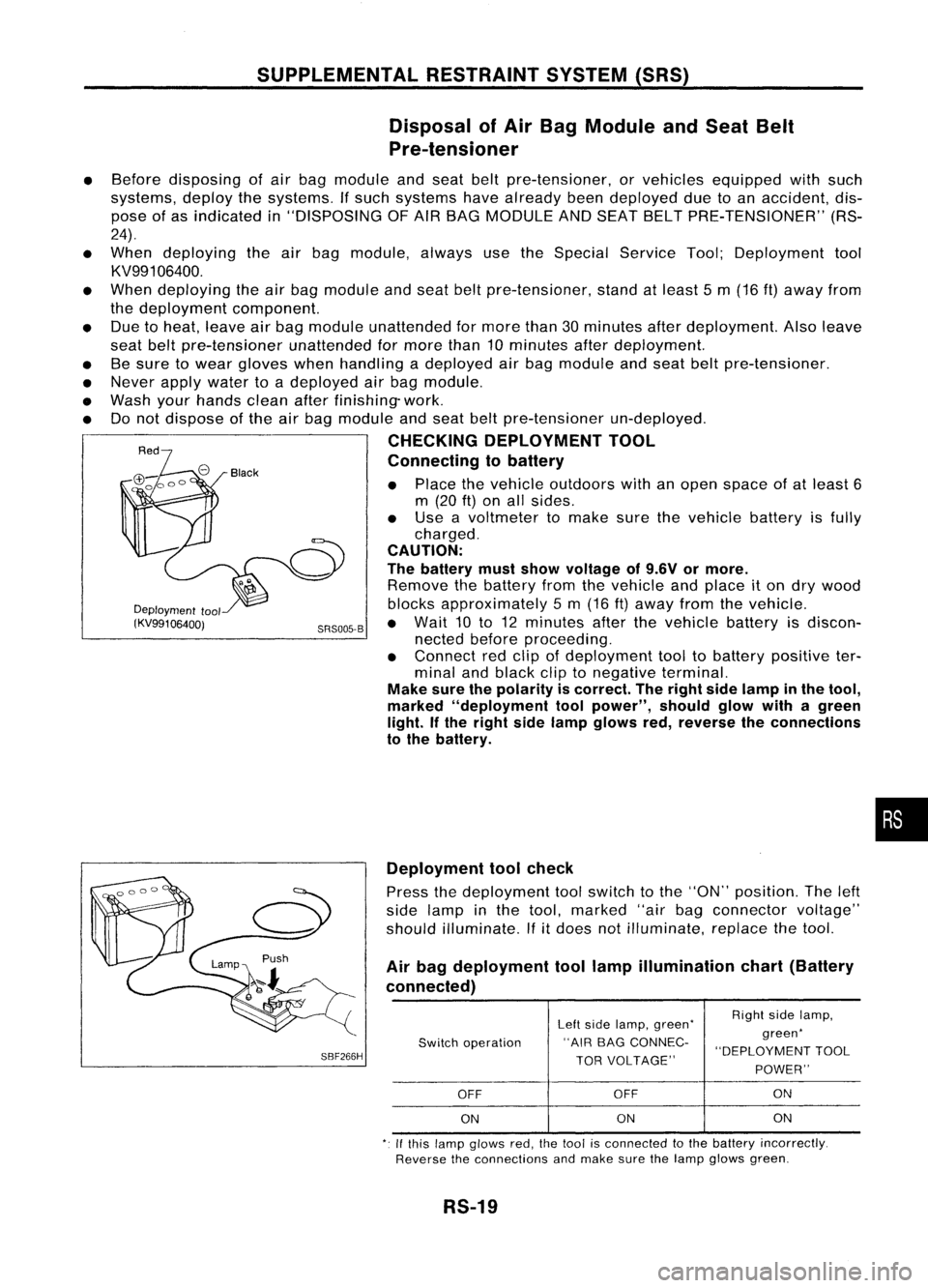
Connecting tobattery
• Place thevehicle outdoors withanopen space ofat least 6
m (20
ft)
on allsides.
• Use avoltmeter tomake surethevehicle batteryisfully
charged.
CAUTION:
The battery mustshow voltage of9.6V ormore.
Remove thebattery fromthevehicle andplace iton dry wood
Deployment
tool blocksapproximately 5m (16 ft)away fromthevehicle.
(KV99106400j SRS005-B•
Wait 10to12 minutes afterthevehicle batteryisdiscon-
nected beforeproceeding.
• Connect redclip ofdeployment tooltobattery positive ter-
minal andblack cliptonegative terminal.
Make surethepolarity iscorrect. Theright sidelamp inthe tool,
marked "deployment toolpower", shouldglowwithagreen
light. Ifthe right sidelamp glows red,reverse theconnections
to the battery.
•
SBF266H Deployment
toolcheck
Press thedeployment toolswitch tothe "ON" position. Theleft
side lamp inthe tool, marked "airbagconnector voltage"
should illuminate.
If
it
does notilluminate, replacethetool.
Air bag deployment toollamp illumination chart(Battery
connected)
Leftside lamp, green' RighI
sidelamp,
Switch operation "AIR
BAGCONNEC- green'
"DEPLOYMENT TOOL
TOR VOLTAGE"
POWER"
OFF OFF ON
ON ON
ON
,. Ifthis lamp glows red,the1001 isconnecled tothe battery incorrectly.
Reverse theconnections andmake surethelamp glows green.
RS-19