1995 NISSAN ALMERA N15 Ecu pin out
[x] Cancel search: Ecu pin outPage 243 of 1701

INTERIORTRIM
Door Trim
(Coni' d)
REMOVAL -Door trim
4-door sedanand5-door hatchback
G)
Remove insidehandle escutcheon.
CID
Remove armrestfinisher frompower window switchassembly anddisconnect theconnector.
@
Remove screwsecuring pullhandle andremove pullhandle.
@
Remove windowregulator handle(Manual windowmodels).
@
Remove bolts,screws andclips ~securing doorfinisher.
@ Lift outdoor finisher.
SEC. 251-267-809-828
Hook
:
~ Manual window regulator handle
Removal
(j)
~? .P"h
~ Flat-bladed
{} screwdriver
@~l
Squeeze theregulator handleclipinplace witha
screwdriver andremove theregulator handlefrom
the regulator shaft.
Set theregulator handleclipasshown infigure
CD.
Installation
Push theregulator handletoinstall itonto theregulator
shaft.
Install theregulator handleinplace asshown inthe figure
with thewindow completely closed.
8T-23
88T055
•
Page 286 of 1701
Approx.125mm (4.92 In) BRAKE
BOOSTER
Inspection
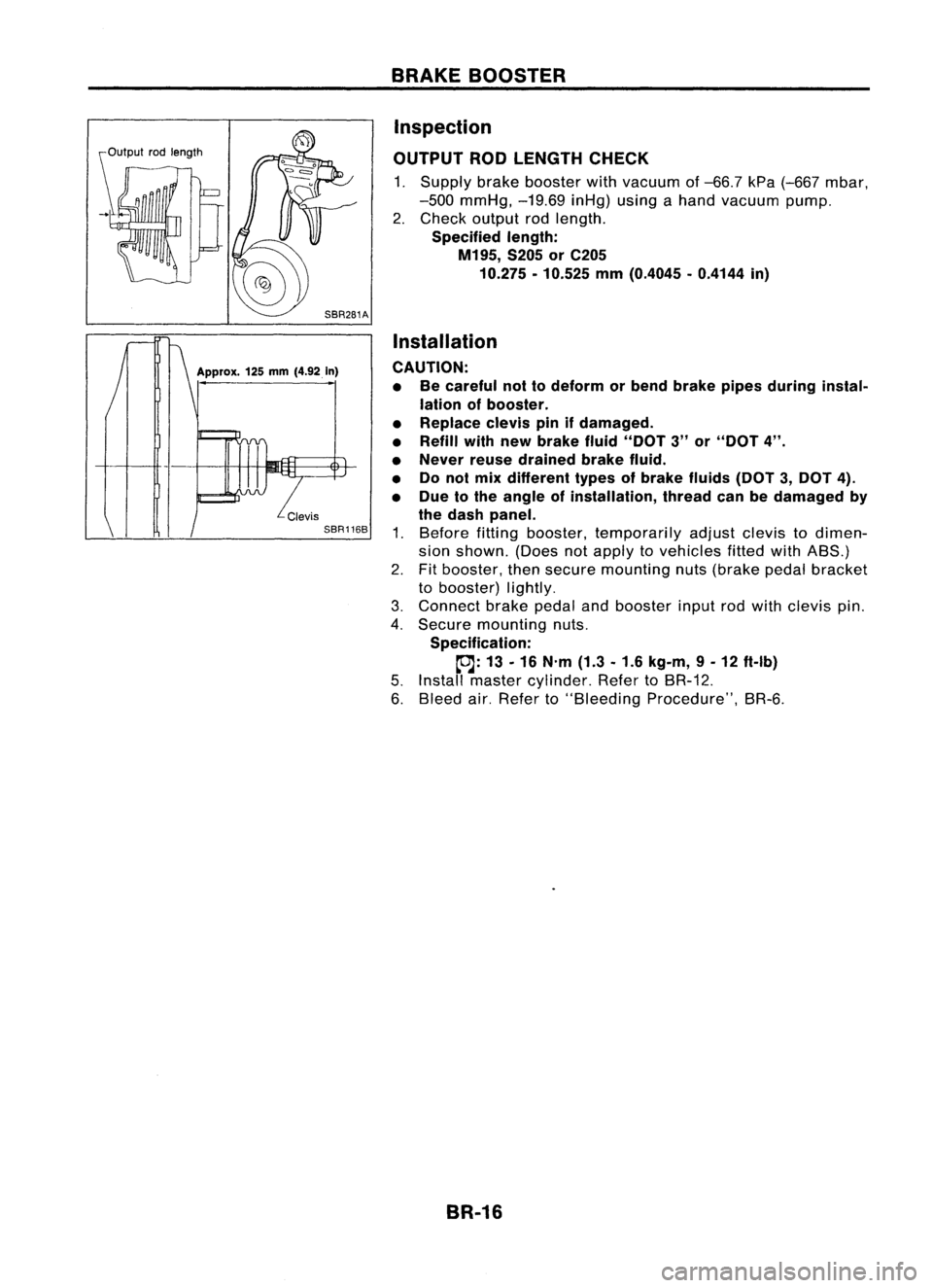
OUTPUT RODLENGTH CHECK
1. Supply brakebooster withvacuum of-66.7 kPa(-667 mbar,
-500 mmHg, -19.69inHg)usingahand vacuum pump.
2. Check output rodlength.
Specified length:
M195, S205orC205
10.275 -10.525 mm(0.4045 -0.4144 in)
Installation
CAUTION: • Becareful nottodeform orbend brake pipesduring instal-
lation ofbooster.
• Replace clevispinifdamaged.
• Refill withnewbrake fluid"DOT 3"or"DOT 4".
• Never reusedrained brakefluid.
• Donol mix different typesofbrake fluids(DOT3,DOT 4).
• Due tothe angle ofinstallation, threadcanbedamaged by
the dash panel.
1. Before fittingbooster, temporarily adjustclevistodimen-
sion shown. (Doesnotapply tovehicles fittedwithABS.)
2. Fitbooster, thensecure mounting nuts(brake pedalbracket
to booster) lightly.
3. Connect brakepedalandbooster inputrodwith clevis pin.
4. Secure mounting nuts.
Specification:
~: 13-16 N'm (1.3-1.6 kg-m, 9-12 ft-Ib)
5. Install master cylinder. RefertoBR-12.
6. Bleed air.Refer to"Bleeding Procedure", BR-6.
BR-16
Page 293 of 1701
Pistonbootretainer (AD22VF only)
Piston boot
Piston seal
FRONT
DISCBRAKE
Inspection -Caliper (Cont'd)
PISTON
Check pistonforscore, rust,wear, damage orpresence offor-
eign objects. Replace ifany ofthe above conditions are
observed.
CAUTION:
Piston sliding surface isplated. Donot polish withemery paper
even ifrust orforeign objects arestuck tosliding surface.
SLIDE PIN,PINBOLT ANDPINBOOT
Check forwear, cracks, rustorother damage. Replaceifany of
the above conditions areobserved.
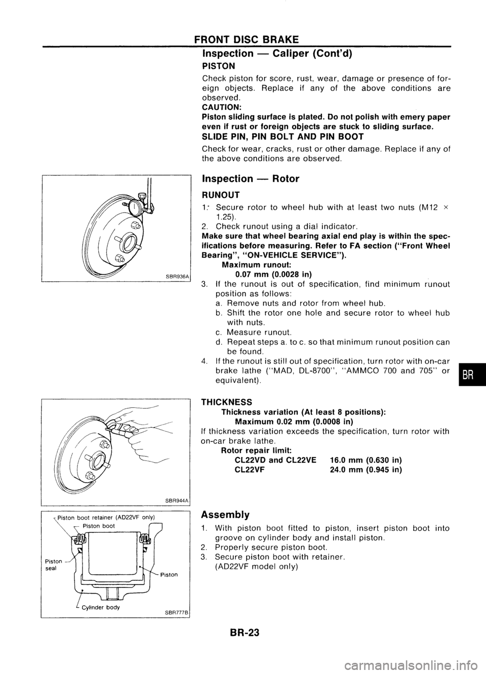
Inspection -Rotor
RUNOUT
1: Secure rotortowheel hubwith atleast twonuts (M12 x
1.25).
2. Check runout usingadial indicator.
Make surethatwheel bearing axialendplay iswithin thespec-
ifications beforemeasuring. RefertoFA section ("FrontWheel
Bearing", "ON-VEHICLE SERVICE").
Maximum runout:
SBR936A 0.07mm(0.0028 in)
3.
If
the runout isout ofspecification, findminimum runout
position asfollows:
a. Remove nutsandrotor fromwheel hub.
b. Shift therotor onehole andsecure rotortowheel hub
with nuts.
c. Measure runout.
d. Repeat stepsa.to c.so that minimum runoutposition can
be found.
4. Ifthe runout isstill outofspecification, turnrotor withon-car
brake lathe("MAD, DL-8700", "AMMCO700and 705" or•••
equivalent).
THICKNESS Thickness variation(Atleast 8positions):
Maximum 0.02mm(0.0008 in)
If thickness variationexceedsthespecification, turnrotor with
on-car brakelathe.
Rotor repair limit:
CL22VD andCL22VE 16.0mm(0.630 in)
CL22VF 24.0mm(0.945 in)
SBR944A Assembly
1. With piston bootfitted topiston, insertpiston bootinto
groove oncylinder bodyandinstall piston.
2. Properly securepistonboot.
3. Secure pistonbootwithretainer.
(AD22VF modelonly)
Piston
SBR777B BR-23
Page 352 of 1701
TROUBLEDIAGNOSES
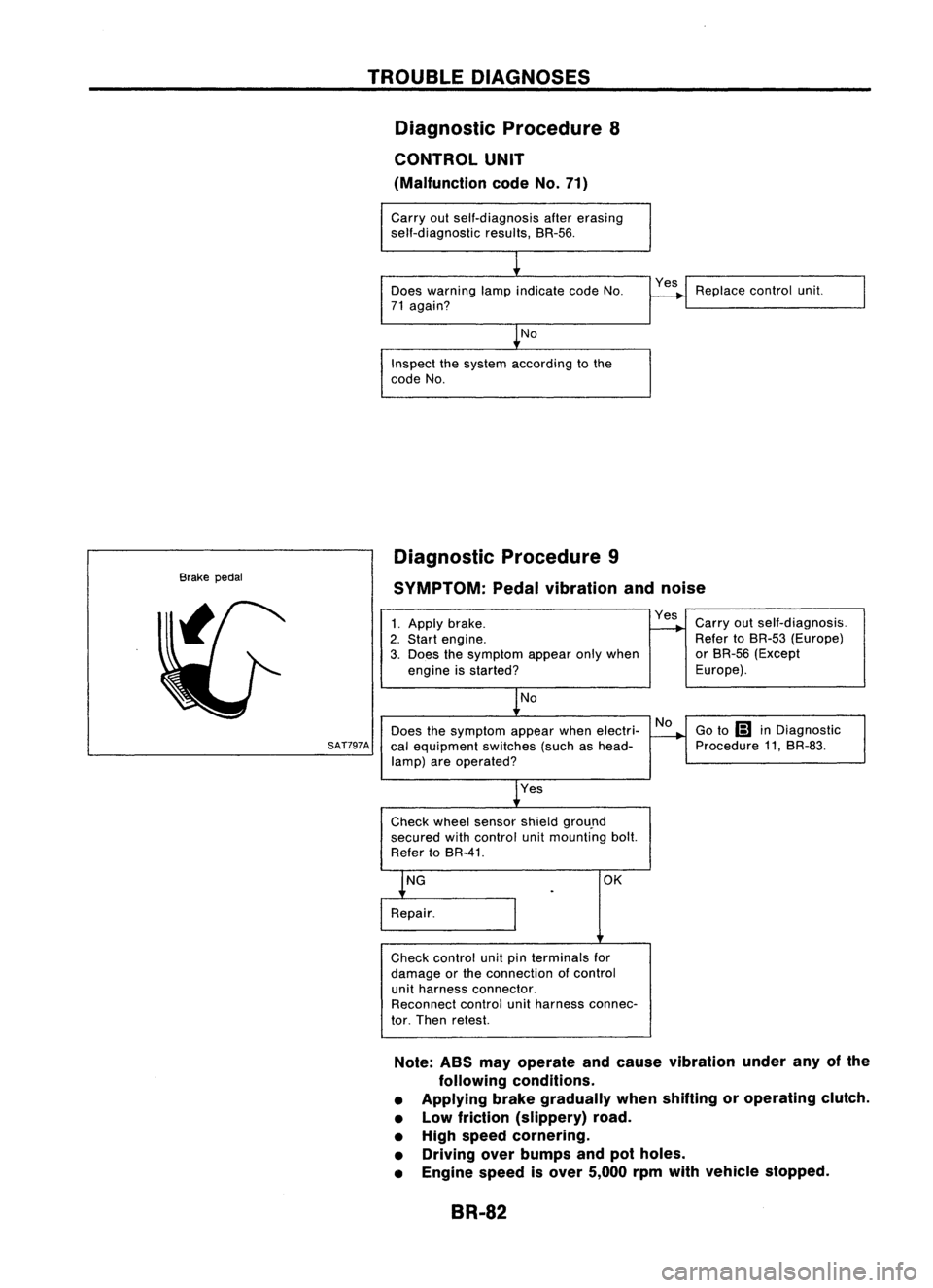
Diagnostic Procedure8
CONTROL UNIT
(Malfunction codeNo.71)
Carry outself-diagnosis aftererasing
self-diagnostic results,BR-56.
Does warning lampindicate codeNo.
71 again?
No
Inspect thesystem according tothe
code No. Yes
Replace controlunit.
Brake pedal Diagnostic
Procedure9
SYMPTOM: Pedalvibration andnoise
No
Does thesymptom appearwhenelectri-
SAT797A
calequipment switches(suchashead-
lamp) areoperated?
1.
Apply brake.
2. Start engine.
3. Does thesymptom appearonlywhen
engine isstarted?
No
Yes
Check wheelsensor shieldgrou.nd
secured withcontrol unitmounting bolt.
Refer toBR-41. Yes
Carryoutself-diagnosis.
Refer toBR-53 (Europe)
or BR-56 (Except
Europe).
Go to
Ii1
inDiagnostic
Procedure 11,BR-83.
OK
Check control unitpinterminals for
damage orthe connection ofcontrol
unit harness connector.
Reconnect controlunitharness connec-
tor. Then retest.
Note: ABSmayoperate andcause vibration underanyofthe
following conditions.
• Applying brakegradually whenshifting oroperating clutch.
• Low friction (slippery) road.
• High speed cornering.
• Driving overbumps andpotholes.
• Engine speedisover 5,000 rpmwith vehicle stopped.
BR-82
Page 728 of 1701
PRECAUTIONSANDPREPARATION
I
GA, SR
I
Precautions forECCS Trouble Diagnosis of
Engine
CAUTION:
• Besure toturn theignition switch"OFF" anddisconnect thenegative batteryterminal beforeany
repair orinspection work.Theopen/short circuitofrelated switches, sensors,solenoidvalves,etc.
will cause malfunction.
• Besure toconnect andlock theconnectors securelyafterwork. Aloose (unlocked) connectorwill
cause malfunction duetothe open circuit. (Besure theconnector isfree from water, grease, dirt,
bent terminals, etc.)
• Besure toroute andclamp theharnesses properlyafterwork. Theinterference ofthe harness with
a bracket, etc.may cause malfunction duetothe short circuit.
• Besure toconnect rubbertubesproperly afterwork. Amisconnected ordisconnected rubbertube•
may cause malfunction.
• Besure toerase theunnecessary malfunctioninformation(repairscompleted) inthe ECM before
returning thevehicle tothe customer.
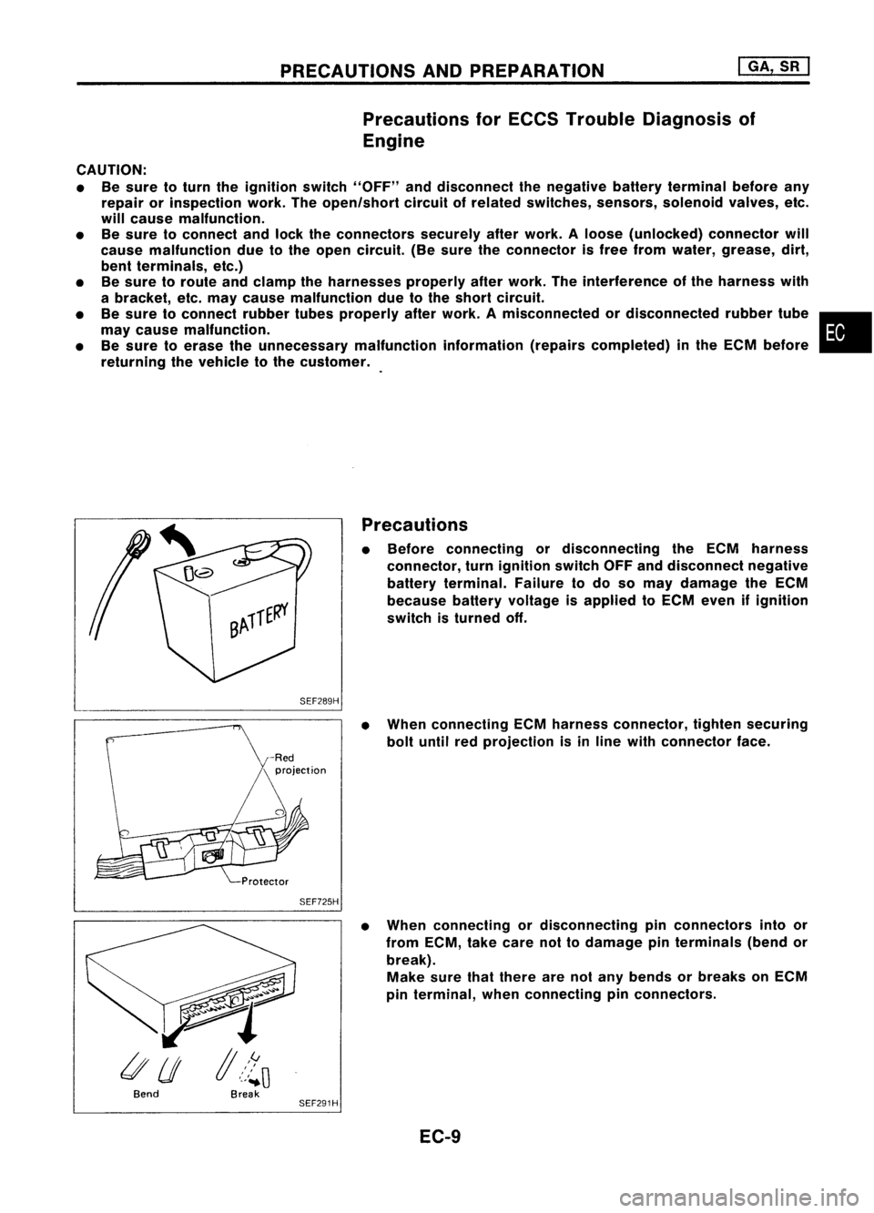
Precautions
• Before connecting ordisconnecting theECM harness
connector, turnignition switchOFFanddisconnect negative
battery terminal. Failuretodo somay damage theECM
because batteryvoltage isapplied toECM even ifignition
switch isturned off.
SEF289H
•When connecting ECMharness connector, tightensecuring
bolt until redprojection isin line with connector face.
SEF725H
•When connecting ordisconnecting pinconnectors intoor
from ECM, takecare nottodamage pinterminals (bendor
break). Make surethatthere arenotany bends orbreaks onECM
pin terminal, whenconnecting pinconnectors.
Bend Break
SEF291H
EC-9
Page 1236 of 1701
IdentificationNo.
\ca
p
\
NO.1
t.:?
Enginefront
SEM420C CYLINDER
BLOCK
Assembly (Cont'd)
•
Front
Pistonringcompressor
SEM293C
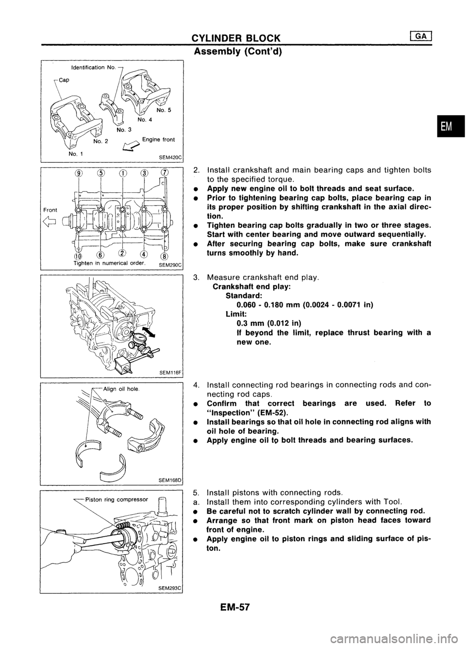
2.
Install crankshaft andmain bearing capsandtighten bolts
to the specified torque.
• Apply newengine oiltobolt threads andseat surface.
• Prior totightening bearingcapbolts, placebearing capin
its proper position byshifting crankshaft inthe axial direc-
tion.
• Tighten bearing capbolts gradually intwo orthree stages.
Start withcenter bearing andmove outward sequentially.
• After securing bearingcapbolts, makesurecrankshaft
turns smoothly byhand.
3. Measure crankshaft endplay.
Crankshaft endplay:
Standard:
0.060 -0.180 mm(0.0024 -0.0071 in)
Limit: 0.3 mm (0.012 in)
If beyond thelimit, replace thrustbearing witha
new one.
4. Install connecting rodbearings inconnecting rodsandcon-
necting rodcaps.
• Confirm thatcorrect bearings areused. Referto
"Inspection" (EM-52).
• Install bearings sothat oilhole inconnecting rodaligns with
oil hole ofbearing.
• Apply engine oiltobolt threads andbearing surfaces.
5. Install pistons withconnecting rods.
a. Install themintocorresponding cylinderswithTool.
• Becareful nottoscratch cylinder wallbyconnecting rod.
• Arrange sothat front mark onpiston headfaces toward
front ofengine.
• Apply engine oiltopiston ringsandsliding surface ofpis-
ton.
EM-57
Page 1357 of 1701
SGI916PRECAUTIONS
• Donot use electrical testequipment onany circuit related •
to the SRS unless instructed tointhis Service Manual.
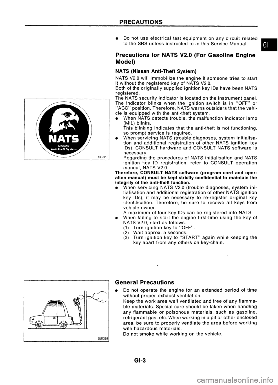
Precautions forNATS V2.0(ForGasoline Engine
Model)
NATS (Nissan Anti-Theft System)
NATS V2.0willimmobilize theengine ifsomeone triestostart
it without theregistered keyofNATS V2.0.
Both ofthe originally suppliedignitionkeyIDshave been NATS
registered.
The NATS security indicator islocated onthe instrument panel.
The indicator blinkswhentheignition switchisin "OFF" or
"ACC" position. Therefore, NATSwarns outsiders thatthevehi-
cle isequipped withtheanti-theft system.
• When NATSdetects trouble, themalfunction indicatorlamp
(MIL) blinks.
This blinking indicates thattheanti-theft isnot functioning,
so prompt service isrequired.
• When servicing NATS(trouble diagnoses, systeminitialisa-
tion andadditional registration ofother NATS ignition key
IDs), CONSULT hardwareandCONSULT NATSsoftware is
necessary.
Regarding theprocedures ofNATS initialisation andNATS
ignition key
10
registration, refertoCONSULT operation
manual, NATSV2.0.
Therefore, CONSULTNATSsoftware (program cardandoper-
ation manual) mustbekept strictly confidential tomaintain the
integrity ofthe anti-theft function.
• When servicing NATSV2.0(trouble diagnoses, systemini-
tial isation andadditional registration ofother NATS ignition
key IDs),
it
may benecessary tore-register originalkey
identification. Therefore,besure toreceive allkeys from
vehicle owner.
A maximum offour keyIDscan beregistered intoNATS.
• When failing tostart theengine first-time usingthekey of
NATS V2.0,startasfollows.
(1) Turn ignition keyto"OFF".
(2) Wait approx. 5seconds.
(3) Turn ignition keyto"START" againwhilekeeping the
key apart fromanyothers onkey-chain.
SGI285 General
Precautions
• Donot operate theengine foranextended periodoftime
without properexhaust ventilation.
Keep thework areawellventilated andfree ofany flamma-
ble materials. Specialcareshould betaken whenhandling
any flammable orpoisonous materials,suchasgasoline,
refrigerant gas,etc.When working inapit orother enclosed
area, besure toproperly ventilate thearea before working
with hazardous materials.
Do not smoke whileworking onthe vehicle.
GI-3
Page 1365 of 1701
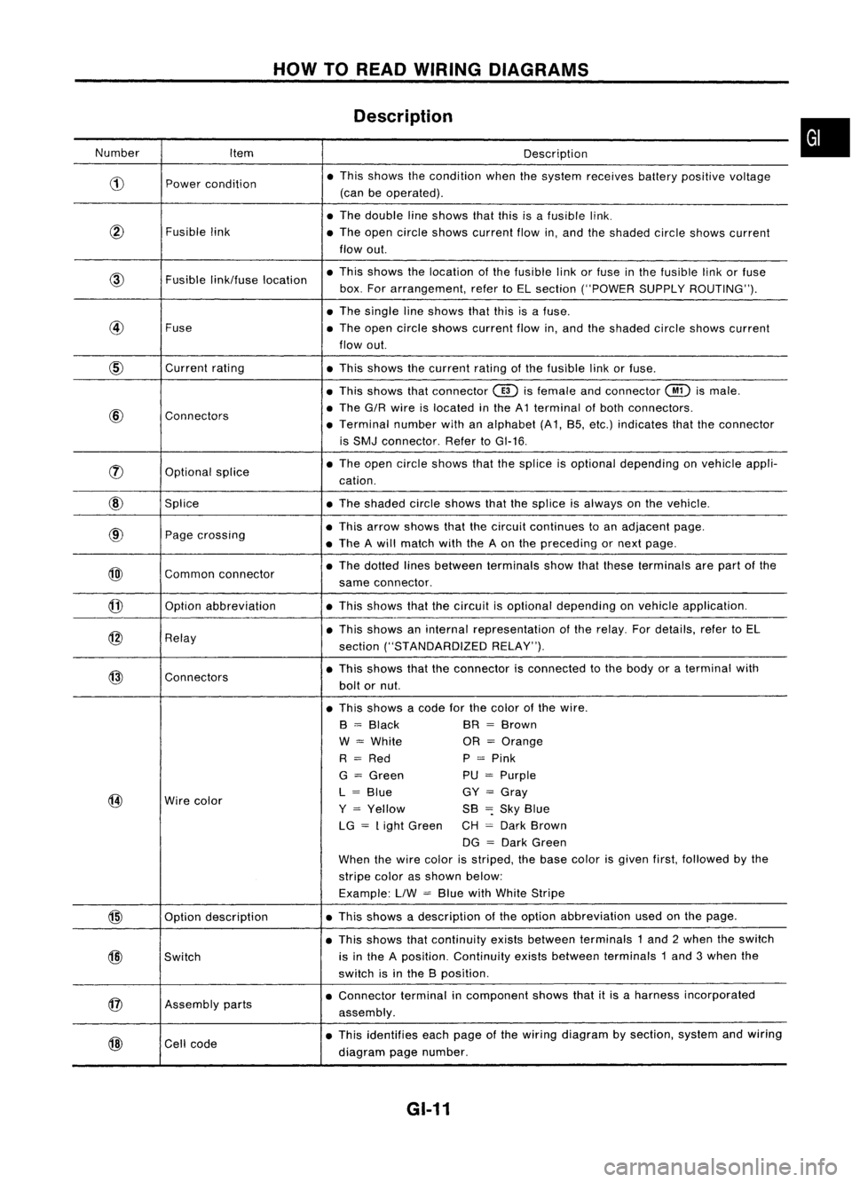
HOWTOREAD WIRING DIAGRAMS
Description
Number Item Description
CD
Power
condition •
This shows thecondition whenthesystem receives batterypositive voltage
(can beoperated) .
• The double lineshows thatthisisafusible link.
@
Fusiblelink
•The open circle shows current flowin,and theshaded circleshows current
flow out.
link/fuse location •
This shows thelocation ofthe fusible linkorfuse inthe fusible linkorfuse
box. Forarrangement, refertoEL section ("POWER SUPPLYROUTING") .
• The single lineshows thatthisisafuse.
@
Fuse
•The open circle shows current flowin,and theshaded circleshows current
flow out.
CID
Current
rating
•This shows thecurrent ratingofthe fusible linkorfuse .
• This shows thatconnector
@)
isfemale andconnector
@
ismale .
@
Connectors •
The G/R wire islocated inthe A1 terminal ofboth connectors.
• Terminal numberwithanalphabet (A1, B5, etc.) indicates thattheconnector
is SMJ connector. RefertoGI-16 .
rJ)
Optionalsplice •
The open circle shows thatthesplice isoptional depending onvehicle appli-
cation.
@
Splice •The shaded circleshows thatthesplice isalways onthe vehicle.
@
Page
crossing •
This arrow shows thatthecircuit continues toan adjacent page.
• The Awill match withtheAon the preceding ornext page .
@)
Commonconnector •
The dotted linesbetween terminals showthatthese terminals arepart ofthe
same connector.
@
Option
abbreviation •This shows thatthecircuit isoptional depending onvehicle application.
@
Relay •
This shows aninternal representation ofthe relay. Fordetails, refertoEL
section ("STANDARDIZED RELAY").
@
Connectors •
This shows thattheconnector isconnected tothe body oraterminal with
bolt ornut.
• This shows acode forthe color ofthe wire.
B
=
Black BR
=
Brown
W
=
White OR
=
Orange
R
=
Red P
=
Pink
G
=
Green PU
=
Purple
@
Wire
color L
=
Blue GY
=
Gray
Y
=
Yellow SB
=:
Sky Blue
LG
=
Light Green CH
=
Dark Brown
DG
=
Dark Green
When thewire color isstriped, thebase color isgiven first,followed bythe
stripe colorasshown below:
Example: LlW
=
Blue withWhite Stripe
@
Optiondescription •
This shows adescription ofthe option abbreviation usedonthe page.
• This shows thatcontinuity existsbetween terminals 1and 2when theswitch
@)
Switch is
inthe Aposition. Continuity existsbetween terminals 1and 3when the
switch isinthe Bposition .
@
Assembly
parts •
Connector terminalincomponent showsthatitis aharness incorporated
assembly .
@
Cell
code •
This identifies eachpage ofthe wiring diagram bysection, systemandwiring
diagram pagenumber.
GI-11
•