1995 NISSAN ALMERA N15 change time
[x] Cancel search: change timePage 285 of 1701

OKNGBRAKE
BOOSTER
On-vehicle Service
OPERATING CHECK
• Depress brakepedalseveral timeswithengine off.After
exhausting vacuum,makesurethere isno change inpedal
stroke.
• Depress brakepedal, thenstart engine. Ifpedal goesdown
slightly, operation isnormal.
AIRTIGHT CHECK
• Start engine, andstop itafter oneortwo minutes. Depress
SBR002A
brakepedalseveral timesslowly. Booster isairtight ifpedal
stroke isless each time.
• Depress brakepedalwhileengine isrunning, andstop
engine withpedal depressed. Thepedal stroke should not
change afterholding pedaldownfor
30seconds.
SBR365AA Removal
CAUTION:
• Becareful nottosplash brakefluidonpainted areas;itmay
cause paintdamage. Ifbrake fluidissplashed onpainted
areas, washitaway withwater immediately.
• Be careful nottodeform orbend brake pipes, during
removal ofbooster.
SEC.
465.470
BR-15Gasket
~ :N.m (kg-m. ft-Ib)
SBR223BB
•
Page 743 of 1701
ENGINEANDEMISSION BASICCONTROL SYSTEMDESCRIPTION
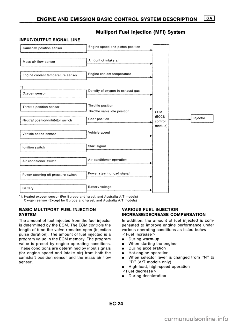
Multipart FuelInjection (MFI)System
INPUT/OUTPUT SIGNALLINE
Camshaft positionsensor
Mass airflow sensor
Engine coolant temperature sensor
*1
Oxygen sensor
Throttle position sensor
Neutral position/Inhibitor switch
Vehicle speedsensor
~gnition switch
Air conditioner switch
Power steering oilpressure switch
Battery Engine
speedandpiston position
Amount ofintake air
Engine coolant temperature
Density ofoxygen inexhaust gas
Throttle position
Throttle valveidleposition
Gear position
Vehicle speed
Start signal
Air conditioner operation
Power steering loadsignal
Battery voltage ECM
(ECCS
control module) Injector
*1: Heated oxygen sensor(ForEurope andIsrael, andAustralia A/Tmodels)
Oxygen sensor(Except forEurope andIsrael, andAustralia A/Tmodels)
BASIC MULTIPORT FUELINJECTION
SYSTEM
The amount offuel injected fromthefuel injector
is determined bythe ECM. TheECM controls the
length oftime thevalve remains open(injection
pulse duration). Theamount offuel injected isa
program valueinthe ECM memory. Theprogram
value ispreset byengine operating conditions.
These conditions aredetermined byinput signals
(for engine speedandintake air)from boththe
camshaft positionsensorandthemass airflow
sensor.
VARIOUS
FUELINJECTION
INCREASE/DECREASE COMPENSATION
In addition, theamount offuel injected iscom-
pensated toimprove engineperformance under
various operating conditions aslisted below.
<
Fuel increase>
• During warm-up
• When starting theengine
• During acceleration
• Hot-engine operation
• When selector leverischanged from"N"to
"D"
(AfT
models only)
• High-load, high-speed operation
<
Fuel decrease>
• During deceleration
EC-24
Page 752 of 1701
BASICSERVICE PROCEDURE
• FUEL PRESRELEASE. D
FUEL PUMP WILLSTOP BY
TOUCHING STARTDURING
IDLE.
CRANK AFEW TIMES AFTER
ENGINE STALL
---S-T~-RT--
SEF823K
Fuel
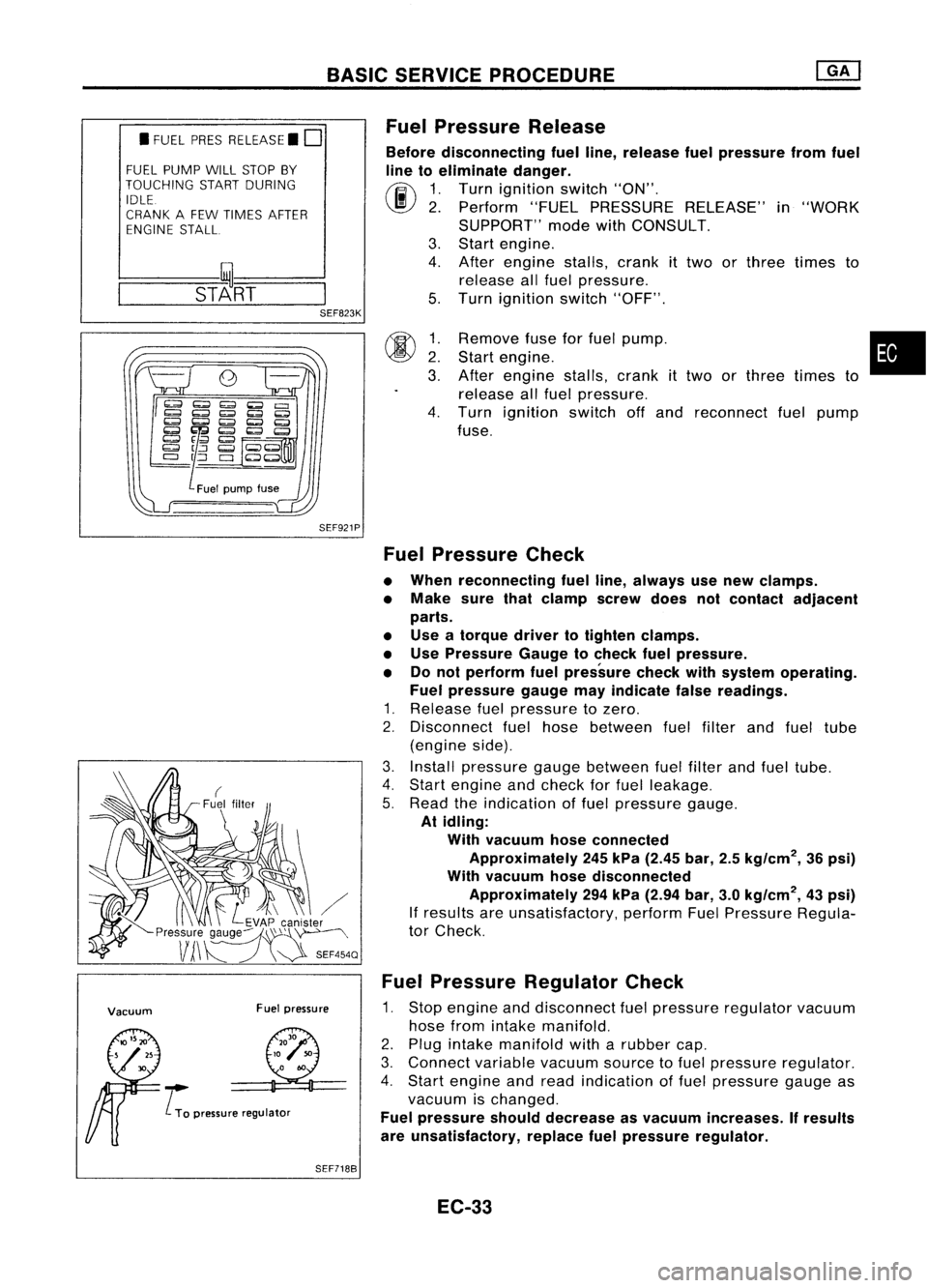
Pressure Release
Before disconnecting fuelline, release fuelpressure fromfuel
line toeliminate danger.
(ij\
1.Turn ignition switch"ON".
~ 2.Perform "FUELPRESSURE RELEASE"in"WORK
SUPPORT" modewithCONSULT.
3. Start engine.
4. After engine stalls,crankittwo orthree times to
release allfuel pressure.
5. Turn ignition switch"OFF".
SEF921P
00
~:
3.
4.
Remove
fuseforfuel pump. •
Start engine.
After engine stalls,crankittwo orthree times to
release allfuel pressure.
Turn ignition switchoffand reconnect fuelpump
fuse.
Vacuum Fuelpressure
..... L
To pressure regulator
Fuel
Pressure Check
• When reconnecting fuelline, always usenew clamps.
• Make surethatclamp screwdoesnotcontact adjacent
parts.
• Use atorque drivertotighten clamps.
• Use Pressure Gaugetocheck fuelpressure.
• Donot perform fuelpressure checkwithsystem operating.
Fuel pressure gaugemayindicate falsereadings.
1. Release fuelpressure tozero.
2. Disconnect fuelhose between fuelfilter andfuel tube
(engine side).
3. Install pressure gaugebetween fuelfilter andfuel tube.
4. Start engine andcheck forfuel leakage.
5. Read theindication offuel pressure gauge.
At idling:
With vacuum hoseconnected
Approximately 245kPa (2.45 bar,2.5kg/cm
2,
36psi)
With vacuum hosedisconnected
Approximately 294kPa (2.94 bar,3.0kg/cm
2,
43psi)
If results areunsatisfactory, performFuelPressure Regula-
tor Check.
Fuel Pressure Regulator Check
1. Stop engine anddisconnect fuelpressure regulator vacuum
hose fromintake manifold.
2. Plug intake manifold witharubber cap.
3. Connect variablevacuumsourcetofuel pressure regulator.
4. Start engine andread indication offuel pressure gaugeas
vacuum ischanged.
Fuel pressure shoulddecrease asvacuum increases. Ifresults
are unsatisfactory, replacefuelpressure regulator.
SEF7188
EC-33
Page 765 of 1701
ON-BOARDDIAGNOSTIC SYSTEMDESCRIPTION @KJ
Malfunction Indicatorlamp(Mil)(Cont'd)
DIAGNOSTIC TESTMODE I-BULB CHECK
In this mode, theMALFUNCTION INDICATORLAMPonthe instrument panelshould stayON.Ifitremains
OFF, check thebulb. Refer toEL section ("WARNING LAMPSANDCHIME") orsee EC-223.
DIAGNOSTIC TESTMODE I-MALFUNCTION WARNING
MALFUNCTION INDICATORLAMP
ON
OFF Condition
Engine coolant temperature sensorcircuitmalfunction oroverheating isdetected, or
the ECM's CPUismalfunctioning.
No malfunction.
• These Diagnostic TroubleCodeNumbers areclarified inDiagnostic TestMode II(SELF-DIAGNOS-
TIC RESULTS).
DIAGNOSTIC TESTMODE II-SELF-DIAGNOSTIC RESULTS
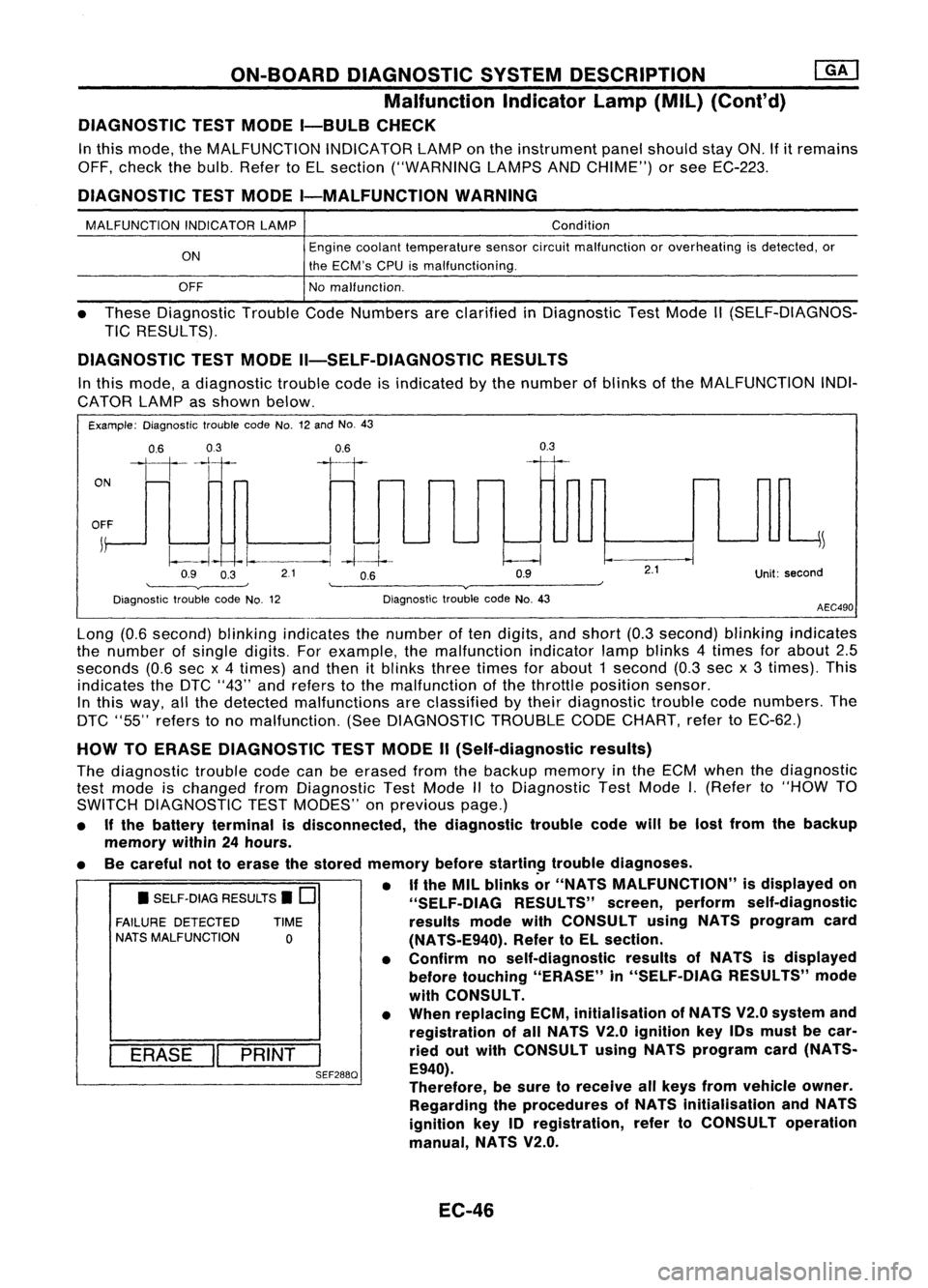
In this mode, adiagnostic troublecodeisindicated bythe number ofblinks ofthe MALFUNCTION INDI-
CATOR LAMPasshown below.
Example: Diagnostic troublecodeNo.12and No.43
ON
0.6
03
111-'1
0.6
II
0.3
OFF
j
~
~~ -I.
--.1
-4--1--
Q9 O~ 21 OB Q9
'--------v----' '--------v------~
Diagnostic troublecodeNo.12 DiagnostictroublecodeNo.43
2.1
Unit:second
AEC490
• SELF-DIAG RESULTS.
0
FAILURE DETECTED TIME
NATS MALFUNCTION
0
I
ERASE
II
PRINT
I
SEF288Q
Long
(0.6second) blinkingindicates thenumber often digits, andshort (0.3second) blinkingindicates
the number ofsingle digits. Forexample, themalfunction indicatorlampblinks 4times forabout 2.5
seconds (0.6secx4 times) andthen itblinks threetimes forabout 1second (0.3secx3 times). This
indicates theDTC "43" andrefers tothe malfunction ofthe throttle position sensor.
In this way, allthe detected malfunctions areclassified bytheir diagnostic troublecodenumbers. The
DTC "55" refers tono malfunction. (SeeDIAGNOSTIC TROUBLECODECHART, refertoEC-62.)
HOW TOERASE DIAGNOSTIC TESTMODE II(Self-diagnostic results)
The diagnostic troublecodecanbeerased fromthebackup memory inthe ECM when thediagnostic
test mode ischanged fromDiagnostic TestMode IIto Diagnostic TestMode
I.
(Refer to"HOW TO
SWITCH DIAGNOSTIC TESTMODES" onprevious page.)
• Ifthe battery terminal isdisconnected, thediagnostic troublecodewillbelost from thebackup
memory within24hours.
• Becareful nottoerase thestored memory before
startin~
troublediagnoses.
• If
the MIL blinks or"NATS MALFUNCTION" isdisplayed on
"SELF-OIAG RESULTS"screen,perform self-diagnostic
results modewithCONSULT usingNATS program card
(NATS-E940). RefertoEL section.
• Confirm noself-diagnostic resultsofNATS isdisplayed
before touching "ERASE" in"SELF-DIAG RESULTS"mode
with CONSULT.
• When replacing ECM,initialisation ofNATS V2.0system and
registration ofall NATS V2.0ignition key10smust becar-
ried outwith CONSULT usingNATS program card(NATS-
E940).
Therefore, besure toreceive allkeys from vehicle owner.
Regarding theprocedures ofNATS initialisation andNATS
ignition key10registration, refertoCONSULT operation
manual, NATS V2.0.
EC-46
Page 772 of 1701

ON-BOARDDIAGNOSTIC SYSTEMDESCRIPTION
CONSULT (Cont'd)
ACTIVE TESTMODE
TEST ITEM CONDITION JUDGEMENT
CHECKITEM(REMEDY)
• Engine: Returntothe original
•Harness andconnector
FUEL INJECTION trouble
condition If
trouble symptom disappears,
•Fuel injectors
• Change theamount offuel see
CHECK ITEM.
injection usingCONSULT . •
Oxygen sensor*1
• Engine: Afterwarming up,idle
IACV-AACIV the
engine.
Enginespeedchanges according •Harness andconnector
OPENING •
Change theIACV-AAC valve
tothe opening percent. •
IACV-AAC valve
opening percentusingCON-
SULT.
• Engine: Returntothe original
•Harness andconnector
ENG COOLANT trouble
condition
Iftrouble symptom disappears, •
Engine coolant temperature
TEMP •
Change theengine coolant
.
see CHECK ITEM. sensor
temperature indicationusing
•Fuel injectors
CONSULT.
• Engine: Returntothe original
trouble condition
Iftrouble symptom disappears,
IGNITION TIMING•
Timing light:Set •
Adjust initialignition timing
• Retard theignition timingusingsee
CHECK ITEM.
CONSULT .
• Engine: Afterwarming up,idle •
Harness andconnector
the engine. •
Compression
POWER •
A/C switch "OFF"
Enginerunsrough ordies . •
Injectors
BALANCE •
Shift lever "N" •
Power transistor
• Cut offeach injector signalone •
Spark plugs
at atime using CONSULT. •
Ignition coils
• Ignition switch:ON
COOLING FAN*3•
Turn thecooling fan"ON" and
Cooling fanmoves andstops. •
Harness andconnector
"OFF", or"LOW" and"HI" •
Cooling fanmotor
and "OFF" usingCONSULT .
• Ignition switch:ON(Engine
FUEL PUMP stopped)
Fuelpump relaymakes theoper- •Harness andconnector
• Turn thefuel pump relay"ON"
RELAY and"OFF" usingCONSULT ating
sound. •
Fuel pump relay
and listen tooperating sound.
EGRC SOLENOID
VALVE (EVAP canister
•Ignition switch:ON
purge control
•Turn solenoid valve"ON" and Solenoid
valvemakes anoperat- •
Harness andconnector
solenoid valveor
EGR valve
&
"OFF"
withtheCONSULT andingsound. •
Solenoid valve
EVAP canister listen
tooperating sound.
purge control
solenoid valve)
•Ignition switch:ON
VALVE TIMING •
Turn solenoid valve"ON" and Solenoid
valvemakes anoperat- •
Harness andconnector
SOL*2 "OFF"
usingCONSULT anding
sound. •
Solenoid valve
listen tooperating sound.
SELF-LEARNING •
Inthis test, thecoefficient ofself-learning controlmixture ratioreturns tothe original coefficient by
CONT touching
"CLEAR" onthe screen.
*1: Heated oxygen sensor(ForEurope andIsrael, andAustralia A/Tmodels)
Oxygen sensor(Except forEurope andIsrael, andAustralia A/Tmodels)
*2: GA16DE except forEurope andIsrael
*3: GA16DE engine A/Tmodels forEurope without heavydutykithave a2- step control [ON/OFF] system."LOW"and"HI"
are shown onCONSULT screentorepresent "ON"condition.
EC-53
•
Page 793 of 1701
TROUBLEDIAGNOSES -General Description
CONSULT ReferenceValueinData Monitor
Mode
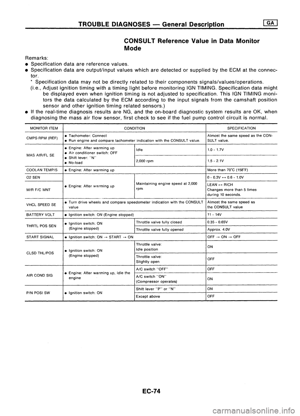
Remarks:
• Specification dataarereference values.
• Specification dataareoutput/input valueswhicharedetected orsupplied bythe ECM atthe connec-
tor.
*
Specification datamaynotbedirectly relatedtotheir components signals/values/operations.
(Le., Adjust ignition timingwithatiming lightbefore monitoring IGNTIMING. Specification datamight
be displayed evenwhen ignition timingisnot adjusted tospecification. ThisIGNTIMING moni-
tors thedata calculated bythe ECM according tothe input signals fromthecamshaft position
sensor andother ignition timingrelated sensors.)
• Ifthe real-time diagnosis resultsareNG, and theon-board diagnostic systemresultsareOK, when
diagnosing themass airflow sensor, firstcheck tosee ifthe fuel pump control circuitisnormal.
MONITOR ITEM
CONDITION SPEC
IFICA TION
CMPS.RPM (REF)•
Tachometer: Connect Almostthesame speed asthe CON-
• Run engine andcompare tachometer indicationwiththeCONSULT value.SULT value.
• Engine: Afterwarming up
Idle 1.0
-1.7V
MAS AIRIFL SE •
Air conditioner switch:OFF
• Shift lever: "N"
• No-load 2,000
rpm 1.5
-2.1V
COOLAN TEMPIS •Engine: Afterwarming up More
than70°C (158°F)
02 SEN 0-
0.3V
<-+
0.6 -1.0V
• Engine: Afterwflrming up Maintaining
enginespeedat2,000
LEAN
<-+
RICH
MIR
FIC
MNT rpm
Changesmorethan5times
during 10seconds .
VHCL SPEED SE•
Turn drive wheels andcompare speedometer indicationwiththeCONSULT Almost
thesame speed as
value the
CONSULT value
SA TTERY VOLT •Ignition switch:ON(Engine stopped) 11
-14V
• Ignition switch:ON Throttle
valvefullyclosed 0.35
-0.65V
THRTL POSSEN
(Enginestopped)
Throttlevalvefullyopened Approx.
4.0V
ST ART SIGNAL •Ignition switch:ON
-->
START
-->
ON OFF
-->
ON
-->
OFF
Throttle valve:
ON
• Ignition switch:ON Idle
position
CLSD THLIPOS
(Enginestopped)
Throttlevalve:
OFF
Slightly open
AIC
switch "OFF" OFF
AIR COND SIG •
Engine: Afterwarming up,idle the
engine
AIC
switch "ON"
ON
(Compressor operate&)
Shift lever "P"or"N" ON
PIN POSI SW •Ignition switch:ON
Exceptabove OFF
EC-74
Page 910 of 1701
2:
1
:>
Q)
Ol
~
0
>
::;
c.
::;
0
,,"--
0
-
Rich- Idealratio _
Lean
Mixlure ratio
SEF288D
•
Zirconia
tube SEF406H
TROUBLE
DIAGNOSIS FORNON-DETECTABLE ITEMS
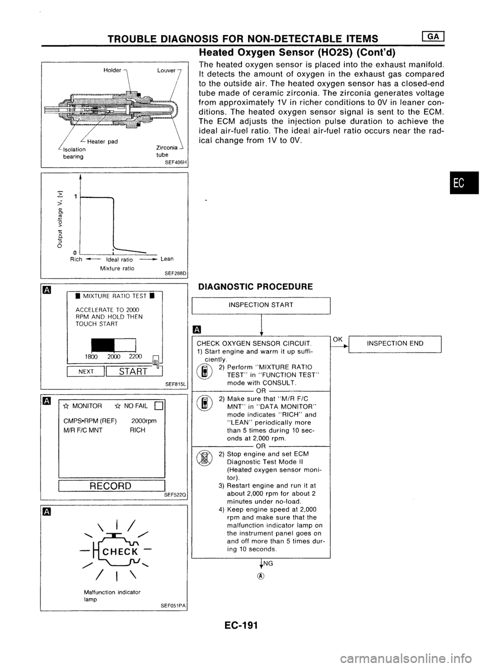
Heated Oxygen Sensor(H02S)(Cont'd)
The heated oxygen sensorisplaced intotheexhaust manifold.
It detects theamount ofoxygen inthe exhaust gascompared
to the outside air.The heated oxygen sensorhasaclosed-end
tube made ofceramic zirconia. Thezirconia generates voltage
from approximately 1Vinricher conditions to
av
inleaner con-
ditions. Theheated oxygen sensorsignalissent tothe ECM.
The ECM adjusts theinjection pulseduration toachieve the
ideal air-fuel ratio.Theideal air-fuel ratiooccurs neartherad-
ical change from1Vto
av.
L
Healerpad
Isolalion
bearing
m
•MIXTURE RATIOTEST.
ACCELERATE TO2000
RPM AND HOLD THEN
TOUCH START
I£J
1800
20002200
~J
NEXT
II
START
SEF815L
m
*
MONITOR
*
NO FAIL
D
CMPS.RPM (REF)2000rpm
MIR FICMNT RICH
DIAGNOSTIC
PROCEDURE
RECORD
\ I/
........ e",/
- CHECK-
",/
........
/ I\
I
SEF522Q
INSPECTION
START
CHECK OXYGEN SENSORCIRCUIT.
1) Start engine andwarm itup suffi-
ciently.
(F.i\
2)Perform "MIXTURE RATIO
~ TEST"in"FUNCTION TEST"
mode withCONSULT.
OR
(F.i\
2)Make surethat"M/R
FIC
~ MNT"in"DATA MONITOR"
mode indicates "RICH"and
"LEAN" periodically more
than 5times during 10 sec-
onds at2,000 rpm.
OR
fti>\
2)Stop engine andsetECM
~ Diagnostic TestMode
/I
(Heated oxygensensormoni-
tor).
3) Restart engineandrunitat
about 2,000rpmforabout 2
minutes underno-load.
4) Keep engine speedat2,000
rpm andmake surethatthe
malfunction indicatorlampon
the instrument panelgoeson
and offmore than5times dur-
ing 10seconds.
NG
@
OK
INSPECTION END
Malfunction indicator
lamp SEF051PA
EC-191
Page 915 of 1701
TROUBLEDIAGNOSIS FORNON-DETECTABLE ITEMS
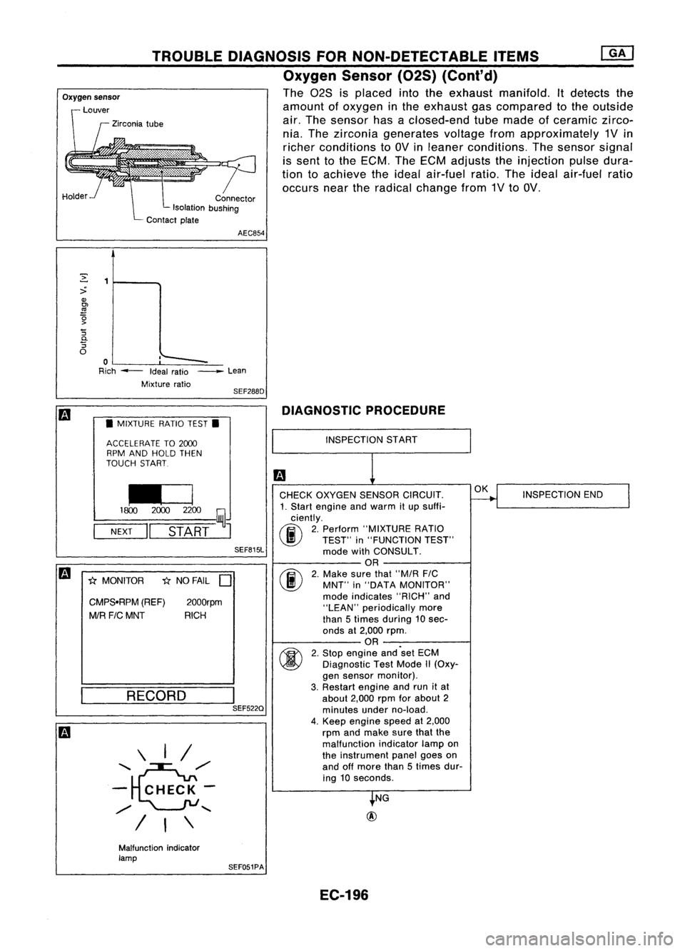
Oxygen Sensor(02S)(Cont'd)
The 028 isplaced intotheexhaust manifold. Itdetects the
amount ofoxygen inthe exhaust gascompared tothe outside
air. The sensor hasaclosed-end tubemade ofceramic zirco-
nia. The zirconia generates voltagefromapproximately 1Vin
richer conditions toOV inleaner conditions. Thesensor signal
is sent tothe ECM. TheECM adjusts theinjection pulsedura-
tion toachieve theideal air-fuel ratio.Theideal air-fuel ratio
occurs neartheradical change from1VtoOV.
r
Connector
Isolation bushing
Contact plate
Oxygen
sensor
Louver
Zirconia tube
Holder AEC854
,'--
~
:>
Q)
OJ
.!!1
~ '5
0-
'5
o
o
Rich --- Idealratio
Mixture ratio_
Lean
SEF288D
m
•MIXTURE RATIOTEST.
ACCELERATE TO2CXXJ
RPM AND HOLD THEN
TOUCH START
~
1800 2CXXJ2200
~J
NEXT
II
START
SEF815L
m
1;{MONITOR 1;{NO FAIL
D
CMPS.RPM (REF)
2000rpm
MIR FICMNT RICH
RECORD \ I/
'~/'
- CHECK-
/
"-
I
I\
I
SEF522Q DIAGNOSTIC
PROCEDURE
INSPECTION START
CHECK OXYGEN SENSORCIRCUIT.
1. Start engine andwarm itup suffi-
ciently.
(F.i\
2.Perform "MIXTURE RATIO
~ TEST"in"FUNCTION TEST"
mode withCONSULT.
OR
(F.i\
2.Make surethat"M/R FIC
\..!!J
MNT"in"DATA MONITOR"
mode indicates "RICH"and
"LEAN" periodically more
than 5times during 10sec-
onds at2,000 rpm.
OR
~ 2.Stop engine and'set ECM
~ Diagnostic TestMode II(Oxy-
gen sensor monitor).
3. Restart engineandrunitat
about 2,000rpmforabout 2
minutes underno-load.
4. Keep engine speedat2,000
rpm andmake surethatthe
malfunction indicatorlampon
the instrument panelgoeson
and offmore than5times dur-
ing 10seconds.
NG
@
OK
INSPECTION END
Malfunction indicator
lamp SEF051PA
EC-196