Page 374 of 1701

CONTENTS(Conl'd.)
Front FogLamp Aiming Adjustment.. 101
Rear FogLamp/Wiring Diagram-R/FOG -102
Turn Signal andHazard Warning Lamps/
Schematic 106
Turn Signal andHazard Warning
Lamps/Wiring Diagram-TURN - 107
Turn Signal andHazard Warning
Lamps/Trouble Diagnoses 113
Combination FlasherUnitCheck 113
Bulb Specifications 114
INTERIOR LAMP 115
Illumination/Schematic 115
Illumination/Wiring Diagram-ILL - 116
Interior, Spot,Trunk Room andLuggage
Room Lamps/Wiring Diagram-INT/L - 122
Bulb Specifications 126
METER ANDGAUGES 127
Combination Meter 127
Speedometer, Tachometer,Temp.andFuel
Gauges/Wiring Diagram-METER - 129
Inspection/Fuel GaugeandWater
Temperature Gauge 133
Inspection/Tachometer 134
Inspection/Speedometer andVehicle Speed
Sensor 135
Fuel Tank Gauge UnitCheck 137
Thermal Transmitter Check 137
Vehicle SpeedSensor SignalCheck 137
WARNING LAMPSANDBUZZER 138
Warning Lamps/Schematic 138
Warning Lamps/Wiring Diagram-WARN -139
Oil Pressure SwitchCheck 151
Fuel Warning LampSensor Check 151
Diode Check 151
Warning BuzzerUnit... 151
Warning Buzzer/System Description 152
Warning Buzzer/Wiring Diagram
- BUZZER - 154
Components Inspection-Warning Buzzer 157
WIPER ANDWASHER 160
Front Wiper andWasher/System Description160
Front Wiper andWasher/Wiring Diagram
- WIPER - 162
Front Wiper Amplifier Check 166
Front Wiper Installation andAdjustment.. 166
Front Wiper Linkage 167
Front Washer NozzleAdjustment... 168
Front Washer TubeLayout 168
Rear Wiper andWasher/System Description169Rear
Wiper andWasher/Wiring Diagram
- WIP/R - 171
Rear Wiper Amplifier Check 175
Rear Wiper Installation andAdjustment.. 175
Rear Washer NozzleAdjustment 175
Rear Washer TubeLayout.. 176
Check Valve(forrear washer) 176
Headlamp WiperandWasher/Wiring Diagram
- HLC - 177
Headlamp WiperMotorCheck 179
Headlamp WiperInstallation 179
Headlamp WasherTubeLayout.. 179
Check Valve(Forheadlamp washer) 179
POWER WINDOW 180
System Description 180
Schematic 183
Wiring Diagram -WINDOW - 185
Trouble Diagnoses 197
POWER DOORLOCK 198
System Description 198
Schematic 200
Wiring Diagram -D/LOCK - 202
Trouble Diagnoses -Type 1(For Europe and
Austral ia) 212
Trouble Diagnoses -Type 2(Except for
Europe andAustralia) 216
POWER DOORMIRROR 220
Wiring Diagram -MIRROR - 220
ELECTRIC SUNROOF 224
Wiring Diagram -SROOF - 224
HORN, CIGARETTE LIGHTERANDCLOCK 226
Wiring Diagram -HORN - 226
REAR WINDOW DEFOGGER ANDDOOR
MIRROR DEFOGGER 230
System Description (Formodels withdaytime
light system) 230
Wirin.g Diagram -DEF - 231
Filament Check 235
Fi lament Repai
r
236
AUDIO ANDANTENNA 237
Audio/System Description 237
Wiring Diagram -AUDIO - 238
Radio FuseCheck 243
Location ofAntenna 243
Antenna RodReplacement.. 243
HEATED SEAT 245
Wiring Diagram -H/SEAT - 245
NATS (Nissan Anti-Theft System) 247
System Description 247
System Composition 247
Page 485 of 1701

EXTERIORLAMP
Turn Signal andHazard Warning Lamps/Trouble
Diagnoses
Symptom Possiblecause Repairorder
Turn signal andhazard warning 1.Hazard switch 1.
Check hazard switch.
lamps donot operate.
2.
Combination flasherunit
2.
Refer tocombination flasherunitcheck.
3.
Open incombination flasher
3.
Check
wiringtocombination flasherunitforopen
unit circuit circuit.
Turn signal lampsdonot operate 1.
7.5A fuse 1.Check
7.5Afuse(No.
[ill,
located infuse block).
but hazard warning lampsoper- Turn
ignition switchONand verify battery positive
ate. voltage
ispresent atterminal
@
ofhazard
switch.
2
Hazard
switch
2.
Check hazard switch.
3.
Turn
signal switch
3.
Check
turnsignal switch.
4.
Open
inturn.signal switchcir.
4.
Check
harness between combination flasherunit
cuit terminal
@and turn signal switch terminal
G)
for open circuit.
Hazard warning lampsdonot 1.
10A fuse 1.Check
10Afuse (No.
ffiJ,
located infuse block).
operate butturn signal lamps Verify
battery positive voltageispresent attermi-
operate. nal
@ofhazard switch.
2.
Hazard switch
2.
Check
hazard switch.
3.
Open inhazard switchcircuit
3.
Check
harness between combination flasherunit
terminal @and hazard switchterminal @for
open circuit.
Individual turnsignal lampor 1.
Bulb 1.
Check bulb.
turn indicators donot operate.
2.
Grounds
2.
Check
ground circuitforthe bulb.
Test lamp (27W)
\ I/
, /
Battery
SEL122E
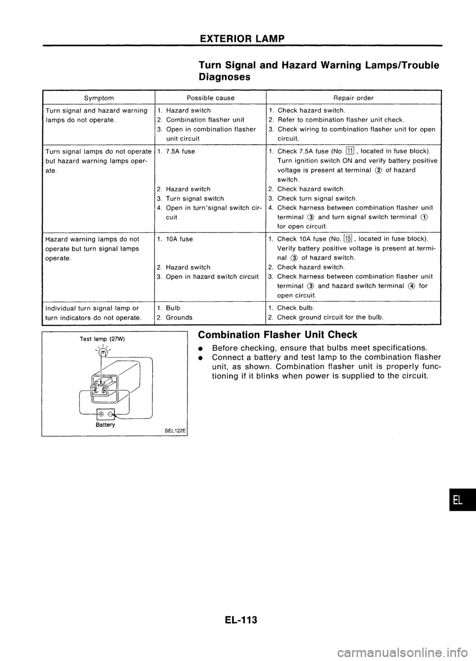
Combination
FlasherUnitCheck
• Before checking, ensurethatbulbs meetspecifications.
• Connect abattery andtestlamp tothe combination flasher
unit, asshown. Combination flasherunitisproperly func-
tioning ifitblinks whenpower issupplied tothe circuit.
EL-113
•
Page 486 of 1701
EXTERIORLAMP
Bulb Specifications
Front turnsignal lamp
Clearance lamp
Front foglamp
Side turnsignal lamp
Rear combination lamp
Turn signal
StoplTail
Tail Back-up
Rear fog
License platelamp
High-mounted stoplamp
Bulb type(Sedan)
Bulb type(Hatchback)
LED type
EL-114
Wattage
(W)
21
5
55
5
21
21/5
5
21
21 5
5 (x6)
21
4.6