Page 196 of 1701
__________ BODYALIGNMENT ___________
BODYALIGNMENT _
Rear Body Sedan
RearBody 3-door
Hatchback
5-door Hatchback
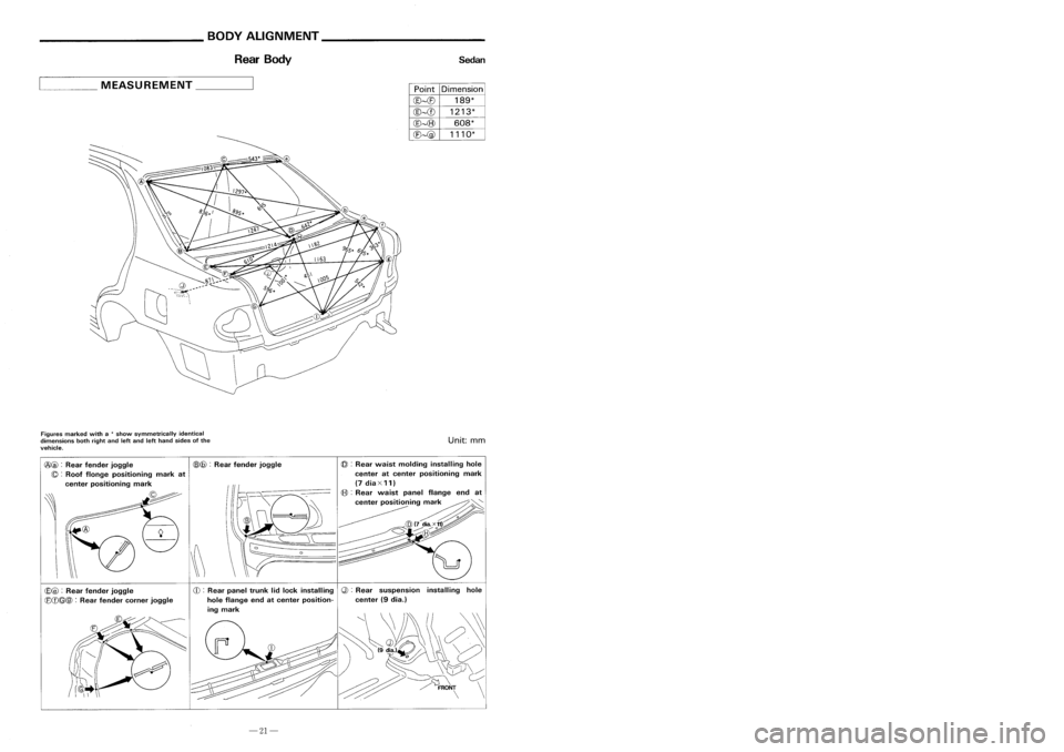
____ MEASUREMENT _
PointDimension
@~(E)
189*
@~CD
1213*
@~(8)
608*
(E)~@
1110*
~
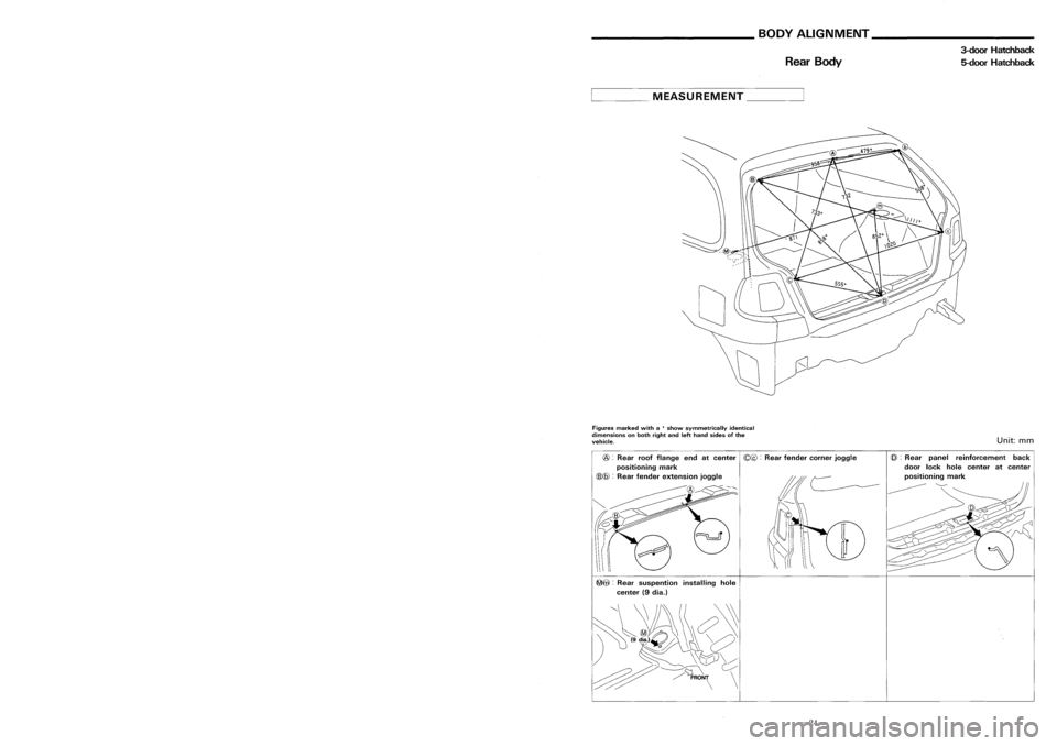
MEASUREMENT _
Figures marked witha
*
show symmetrically identical
dimensions bothright andleftand lefthand sides ofthe
vehicle.
Unit:
mm
Figures
marked witha
*
show symmetrically identical
dimensions onboth right andlefthand sides ofthe
vehicle.
Unit:
mm
@ :
Rear panel reinforcement back
door lockhole center atcenter
~@ :
Rear suspention installinghole
center (9dia.)
@
:
Rear roofflange endatcenter
(Q@:
Rearfender cornerjoggle
positioning mark
(6)@ :
Rear fender extension joggle
CD :
Rear panel trunklidlock installing
Q):
Rear suspension installinghole
hole flange endatcenter position- center(9dia.)
ing mark
\~
CE)@ :
Rear fender joggle
(8(f)
Rear fender cornerjoggle
@@
:
Rear fender joggle
(6)@:
Rear fender joggle
(Q :
Roof flonge positioning markat
center positioning mark
-21-
-24-
Page 199 of 1701
__________ BODYALIGNMENT ___________
BODYALIGNMENT _
Rear Body Sedan
RearBody 3-door
Hatchback
5-door Hatchback
____ MEASUREMENT _
PointDimension
@~(E)
189*
@~CD
1213*
@~(8)
608*
(E)~@
1110*
~
MEASUREMENT _
Figures marked witha
*
show symmetrically identical
dimensions bothright andleftand lefthand sides ofthe
vehicle.
Unit:
mm
Figures
marked witha
*
show symmetrically identical
dimensions onboth right andlefthand sides ofthe
vehicle.
Unit:
mm
@ :
Rear panel reinforcement back
door lockhole center atcenter
~@ :
Rear suspention installinghole
center (9dia.)
@
:
Rear roofflange endatcenter
(Q@:
Rearfender cornerjoggle
positioning mark
(6)@ :
Rear fender extension joggle
CD :
Rear panel trunklidlock installing
Q):
Rear suspension installinghole
hole flange endatcenter position- center(9dia.)
ing mark
\~
CE)@ :
Rear fender joggle
(8(f)
Rear fender cornerjoggle
@@
:
Rear fender joggle
(6)@:
Rear fender joggle
(Q :
Roof flonge positioning markat
center positioning mark
-21-
-24-
Page 227 of 1701
BODYEND
Body RearEndandOpener
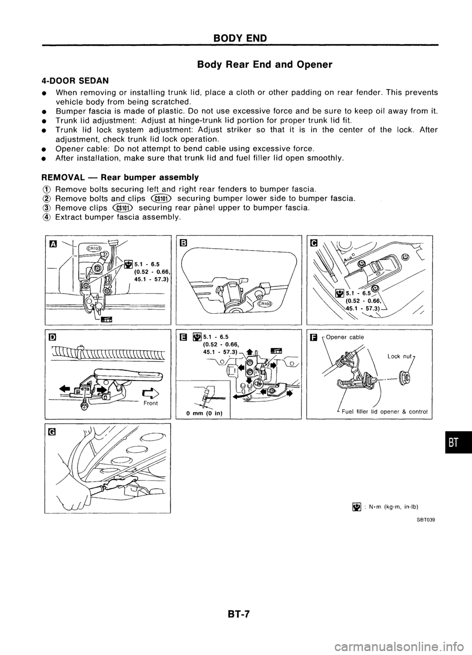
4-DOOR SEDAN
• When removing orinstalling trunklid,place acloth orother padding onrear fender. Thisprevents
vehicle bodyfrombeing scratched.
• Bumper fasciaismade ofplastic. Donot use excessive forceandbesure tokeep oilaway fromit.
• Trunk lidadjustment: Adjustathinge-trunk lidportion forproper trunklidfit.
• Trunk lidlock system adjustment: Adjuststriker sothat itis inthe center ofthe lock. After
adjustment, checktrunklidlock operation.
• Opener cable:Donot attempt tobend cable usingexcessive force.
• After installation, makesurethattrunk lidand fuel filler lidopen smoothly.
REMOVAL -Rear bumper assembly
CD
Remove boltssecuring leHand right rearfenders tobumper fascia.
@
Remove boltsandclips
@ID
securing bumperlowersidetobumper fascia.
@
Remove clips
@ID
securing rearpimel upper tobumper fascia.
@
Extract bumper fasciaassembly.
rn
'11IInff\
\W,\\CC\\\\\\\\\\\\\\
[;I
~5.1 .6.5
(;I
(0.52 •0.66,
45.1 -57.3)~n
m
__ \.QL_OIT~~T~
Jf-~~
o
mm
(0
in)
B1-7 Fuel
fillerlidopener &control
~ :N'm (kg-m, in-Ib)
SBT039
•
Page 229 of 1701
BODYEND
Body RearEndandOpener (Cont'd)
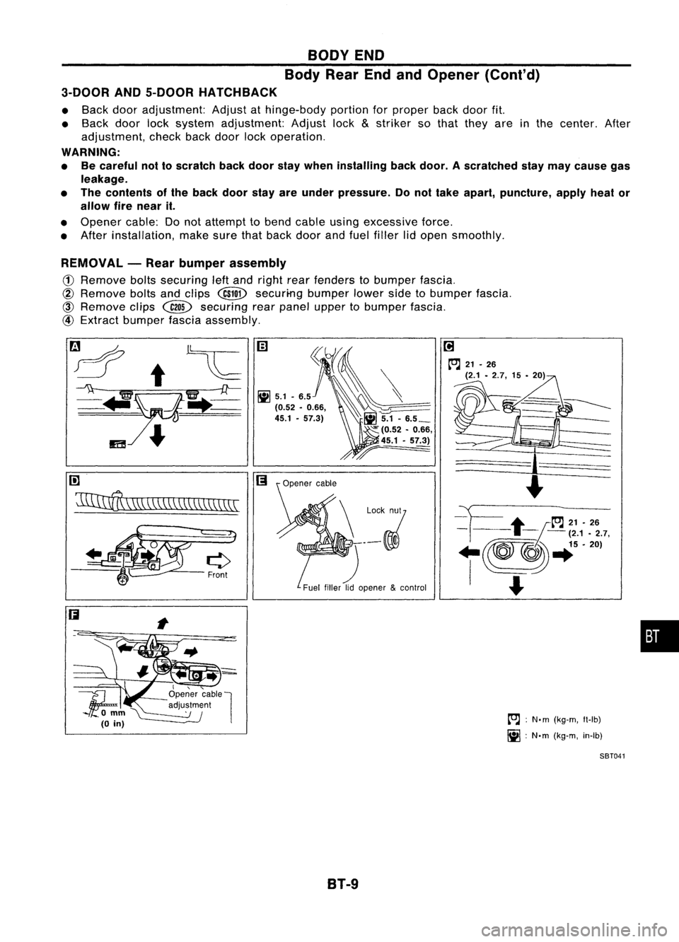
3-DOOR AND5-DOOR HATCHBACK
• Back dooradjustment: Adjustathinge-body portionforproper backdoorfit.
• Back doorlocksystem adjustment: Adjustlock
&
striker sothat they areinthe center. After
adjustment, checkbackdoor lockoperation.
WARNING:
• Becareful nottoscratch backdoor staywhen installing backdoor. Ascratched staymay cause gas
leakage.
• The contents ofthe back doorstayareunder pressure. Donot take apart, puncture, applyheator
allow firenear it.
• Opener cable:Donot attempt tobend cable usingexcessive force.
• After installation, makesurethatback doorandfuel filler lidopen smoothly.
REMOVAL -Rear bumper assembly
(1)
Remove boltssecuring leftand right rearfenders tobumper fascia.
@
Remove boltsandclips
@ill>
securi-ng bumperlowersidetobumper fascia.
@)
Remove clips~ securing rearpanel upper tobumper fascia.
@
Extract bumper fasciaassembly.
rn
~\\\\\\\\\\\\\\\\\\\\\\
I,"-
1f;
Openercable
l
'\ '--- adju~~m~nl
omm~
(0
in)
B1-9
[O.J
:
N.m (kg-m, Il-Ib)
~ :N'm (kg-m, in-Ib)
SBT041
•
Page 231 of 1701
DOOR
Front Door
• For removal ofdoor trim, referto"Door Trim"in"INTERIOR TRIM"fordetails, 8T-22.
• After adjusting doorordoor lock,check doorlockoperation.
SEC. 800-803-805
Outsidehandle
escutcheon --:__
/~
'.
'
~~
~
Bell
crank adjustment
Striker
adjustment ~
c1
=:-/~
g3-
.1~.6,
.. @~\
9-12)
..
~
, -- Outside handleadjustment
(Turn holder asthe clearance between
holder
&
rod isspecified value.)
BT-11
~
:N'm (kg-m, ft-Ib)
Ii] :
N'm (kg-m, in-Ib)
SBT044
•
Page 374 of 1701

CONTENTS(Conl'd.)
Front FogLamp Aiming Adjustment.. 101
Rear FogLamp/Wiring Diagram-R/FOG -102
Turn Signal andHazard Warning Lamps/
Schematic 106
Turn Signal andHazard Warning
Lamps/Wiring Diagram-TURN - 107
Turn Signal andHazard Warning
Lamps/Trouble Diagnoses 113
Combination FlasherUnitCheck 113
Bulb Specifications 114
INTERIOR LAMP 115
Illumination/Schematic 115
Illumination/Wiring Diagram-ILL - 116
Interior, Spot,Trunk Room andLuggage
Room Lamps/Wiring Diagram-INT/L - 122
Bulb Specifications 126
METER ANDGAUGES 127
Combination Meter 127
Speedometer, Tachometer,Temp.andFuel
Gauges/Wiring Diagram-METER - 129
Inspection/Fuel GaugeandWater
Temperature Gauge 133
Inspection/Tachometer 134
Inspection/Speedometer andVehicle Speed
Sensor 135
Fuel Tank Gauge UnitCheck 137
Thermal Transmitter Check 137
Vehicle SpeedSensor SignalCheck 137
WARNING LAMPSANDBUZZER 138
Warning Lamps/Schematic 138
Warning Lamps/Wiring Diagram-WARN -139
Oil Pressure SwitchCheck 151
Fuel Warning LampSensor Check 151
Diode Check 151
Warning BuzzerUnit... 151
Warning Buzzer/System Description 152
Warning Buzzer/Wiring Diagram
- BUZZER - 154
Components Inspection-Warning Buzzer 157
WIPER ANDWASHER 160
Front Wiper andWasher/System Description160
Front Wiper andWasher/Wiring Diagram
- WIPER - 162
Front Wiper Amplifier Check 166
Front Wiper Installation andAdjustment.. 166
Front Wiper Linkage 167
Front Washer NozzleAdjustment... 168
Front Washer TubeLayout 168
Rear Wiper andWasher/System Description169Rear
Wiper andWasher/Wiring Diagram
- WIP/R - 171
Rear Wiper Amplifier Check 175
Rear Wiper Installation andAdjustment.. 175
Rear Washer NozzleAdjustment 175
Rear Washer TubeLayout.. 176
Check Valve(forrear washer) 176
Headlamp WiperandWasher/Wiring Diagram
- HLC - 177
Headlamp WiperMotorCheck 179
Headlamp WiperInstallation 179
Headlamp WasherTubeLayout.. 179
Check Valve(Forheadlamp washer) 179
POWER WINDOW 180
System Description 180
Schematic 183
Wiring Diagram -WINDOW - 185
Trouble Diagnoses 197
POWER DOORLOCK 198
System Description 198
Schematic 200
Wiring Diagram -D/LOCK - 202
Trouble Diagnoses -Type 1(For Europe and
Austral ia) 212
Trouble Diagnoses -Type 2(Except for
Europe andAustralia) 216
POWER DOORMIRROR 220
Wiring Diagram -MIRROR - 220
ELECTRIC SUNROOF 224
Wiring Diagram -SROOF - 224
HORN, CIGARETTE LIGHTERANDCLOCK 226
Wiring Diagram -HORN - 226
REAR WINDOW DEFOGGER ANDDOOR
MIRROR DEFOGGER 230
System Description (Formodels withdaytime
light system) 230
Wirin.g Diagram -DEF - 231
Filament Check 235
Fi lament Repai
r
236
AUDIO ANDANTENNA 237
Audio/System Description 237
Wiring Diagram -AUDIO - 238
Radio FuseCheck 243
Location ofAntenna 243
Antenna RodReplacement.. 243
HEATED SEAT 245
Wiring Diagram -H/SEAT - 245
NATS (Nissan Anti-Theft System) 247
System Description 247
System Composition 247
Page 375 of 1701
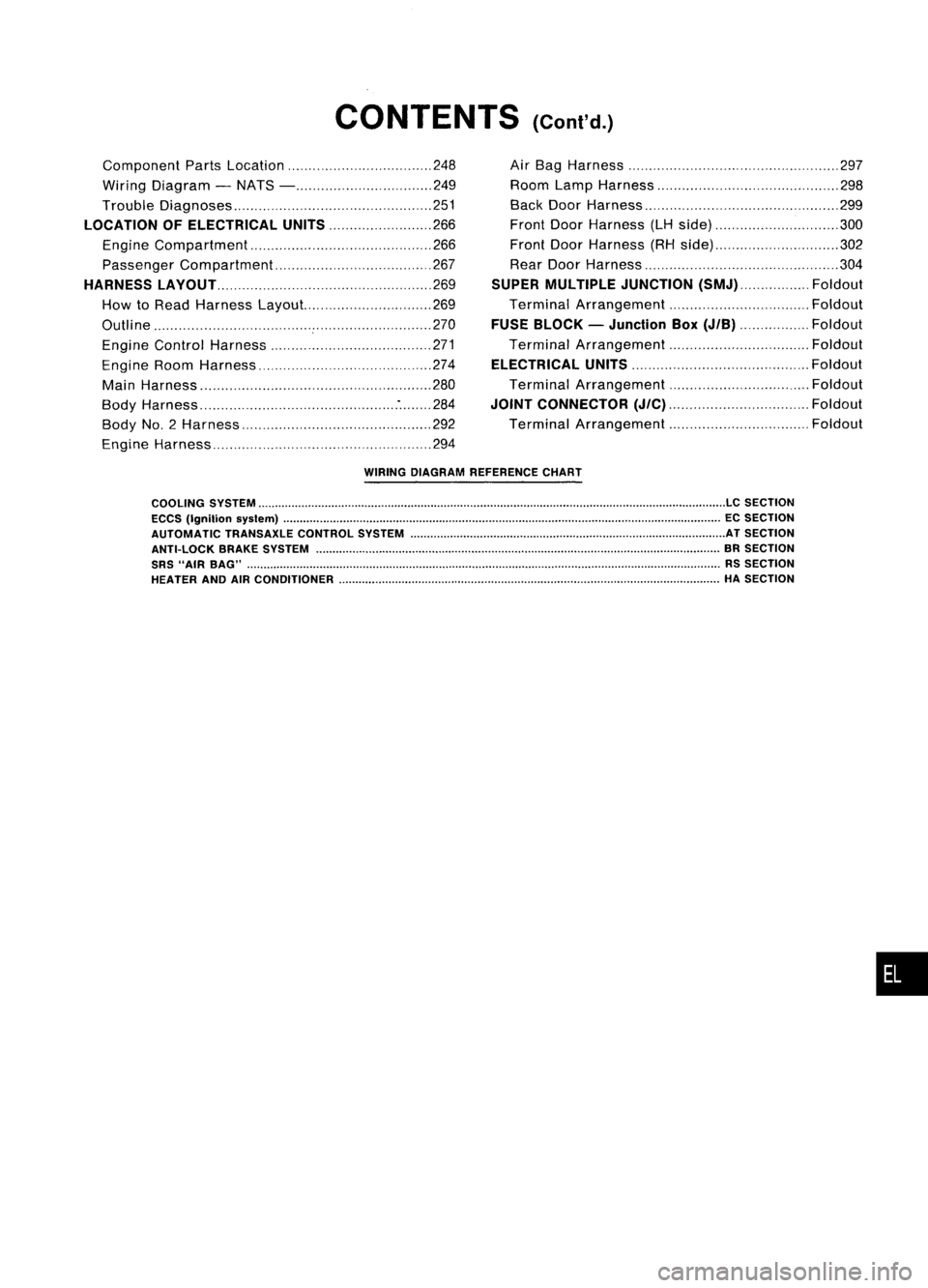
CONTENTS(Cont'd.)
Component PartsLocation 248
Wiring Diagram -NATS - 249
Trouble Diagnoses 251
LOCATION OFELECTRICAL UNITS
266
Engine Compartment 266
Passenger Compartment 267
HARNESS LAyOUT
269
How toRead Harness Layout... 269
Outline 270
Engine Control Harness 271
Engine RoomHarness 274
Main Harness '" 280
Body Harness :284
Body No.2 Harness 292
Engine Harness 294Air
Bag Harness 297
Room LampHarness 298
Back DoorHarness 299
Front DoorHarness (LHside) 300
Front DoorHarness (RHside) 302
Rear Door Harness 304
SUPER MULTIPLE JUNCTION
(SMJ) Foldout
Terminal Arrangement Foldout
FUSE BLOCK -Junction Box
(JIB)
Foldout
Terminal Arrangement Foldout
ELECTRICAL UNITS
Foldout
Terminal Arrangement Foldout
JOINT CONNECTOR
(J/C)
Foldout
Terminal Arrangement Foldout
WIRING DIAGRAM REFERENCE CHART
COOLING SYSTEM
LC
SECTION
ECCS (Ignition syslem) ECSECTION
AUTOMATIC TRANSAXLECONTROLSYSTEM ATSECTION
ANTI-LOCK BRAKESYSTEM BRSECTION
SRS "AIR BAG" RSSECTION
HEATER ANDAIRCONDITIONER HASECTION
•
Page 391 of 1701
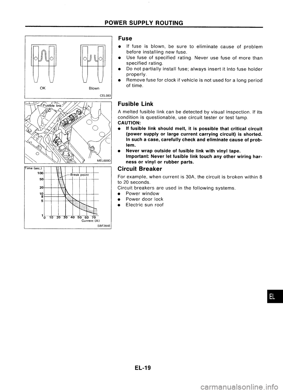
POWERSUPPLY ROUTING
OK BlownFuse
• Iffuse isblown, besure toeliminate causeofproblem
before installing newfuse.
• Use fuse ofspecified rating.Neverusefuse ofmore than
specified rating.
• Donot partially installfuse;always insertitinto fuse holder
properly.
• Remove fuseforclock ifvehicle isnot used foralong period
of time.
ime (sec.)
100
50
20
10
8
5
CEL083
Fusible Link
A melted fusible linkcan bedetected byvisual inspection.
If
its
condition isquestionable, usecircuit testerortest lamp.
CAUTION:
• Iffusible linkshould melt,itis possible thatcritical circuit
(power supplyorlarge current carrying circuit)isshorted.
In such acase, carefully checkandeliminate causeofprob-
lem.
• Never wrapoutside offusible linkwith vinyl tape.
Important: Neverletfusible linktouch anyother wiring har-
ness orvinyl orrubber parts.
Circuit Breaker
For example, whencurrent is30A, thecircuit isbroken within8
to 20 seconds.
Circuit breakers areused inthe following systems.
• Power window
• Power doorlock
• Electric sunroof
SBF284E
EL-19
•