1995 NISSAN ALMERA N15 Throttle
[x] Cancel search: ThrottlePage 1 of 1701

AUTOMATICTRANSAXLE
SECTION
AT
CONTENTS
PREPARATION ANDPRECAUTIONS
3
Special Service Tools 3
Commercial ServiceTools 6
Service Notice 7
Supplemental RestraintSystem(SRS)"AIR
BAG" (DualAirBag System) 7
Supplemental RestraintSystem(SRS)"AIR
BAG" (Single AirBag System) 7
DESCRIPTION
8
Cross-sectional View 8
Hydraulic ControlCircuit 10
Shift Mechanism 14
Control System 15
TROUBLE DIAGNOSES 17
Preliminary Check(PriortoRoad Testing) 17
Road Testing 17
Stall Tasting 24
Pressure Testing 26
Wiring Diagram -AT - 28
Electrical Components Inspection 30
ON-VEHICLE SERVICE 31
Control ValveAssembly andAccumulator 31
Throttle WireAdjustment.. 33
Control CableInstallation andAdjustment 35
Governor Valve 36
Inhibitor SwitchAdjustment 37
Differential SideOilSeal Replacement.. 37
REMOVAL ANDINSTALLATION
39
Removal 39
Installation .40MAJOR
OVERHAUL.. 42
All Models 42
Except Model34X81 .44
Model 34X81 45•
Shift Control Components 46
i
Oil Channel 47
Locations ofAdjusting Shims,Needle
Bearings, ThrustWashers andSnap Rings -
Except Model34X81 .48
Locations ofAdjusting Shims,Needle
Bearings, ThrustWashers andSnap Rings -
Model 34X81 .49
DiSASSEMBLy 50
REPAIR FORCOMPONENT PARTS 66
Manual ShaftandThrottle Lever 66
Oil Pump 70
Control ValveAssembly 74
Control ValveUpper Body 86
Control ValveLower Body 90
Reverse Clutch 93
High Clutch 97
Forward ClutchandOverrun Clutch 102
Low &Reverse Brake 108
Rear Internal Gear,Forward ClutchHuband
Overrun ClutchHub 112
Output Shaft,Output Gear,IdlerGear,
Reduction PinionGearandBearing Retainer
- Except Model34X81 116
Output Shaft,IdlerGear, Reduction Pinion
Gear andBearing Retainer -Model 34X81 121
Band Servo Piston Assembly 126
Final Drive -Except Model34X81 131
Final Drive -Model 34X81 135
Page 3 of 1701
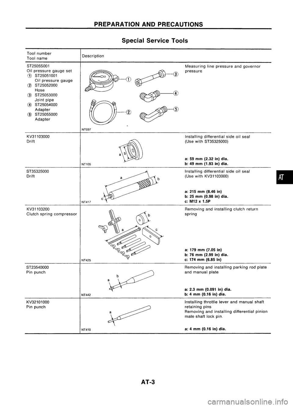
Toolnumber
Tool name
PREPARATION
ANDPRECAUTIONS
Special Service Tools
Description
8T25058001
Oil pressure gaugeset
G)
8T25051001
Oil pressure gauge
@ 8T25052000
Hose
@
8T25053000
Joint pipe
@
8T25054000
Adapter
@
8T25055000
Adapter Measuring
linepressure andgovernor
pressure
NT097
KV31103000
Drift
8T35325000 Drift
KV31103200
Clutch spring compressor
8T23540000 Pin punch
KV32101000
Pin punch
NT105
NT417
NT425
NT442
NT410
AT-3
Installing
differential sideoilseal
(Use with8T35325000)
a: 59 mm (2.32 in)dia.
b: 49 mm (1.93 in)dia.
Installing differential sideoilseal
(Use withKV31103000)
a: 215 mm (8.46 in)
b: 25 mm (0.98 in)dia.
c: M12 x1.5P
Removing andinstalling clutchreturn
spring
a: 179 mm (7.05 in)
b: 76 mm (2.99 in)dia.
c: 174 mm (6.85 in)
Removing andinstalling parkingrodplate
and manual plate
a: 2.3 mm (0.091 in)dia.
b: 4mm (0.16 in)dia.
Installing throttleleverandmanual shaft
retaining pins
Removing andinstalling differential pinion
mate shaft lockpin.
a: 4mm (0.16 in)dia.
•
Page 12 of 1701
DESCRIPTION
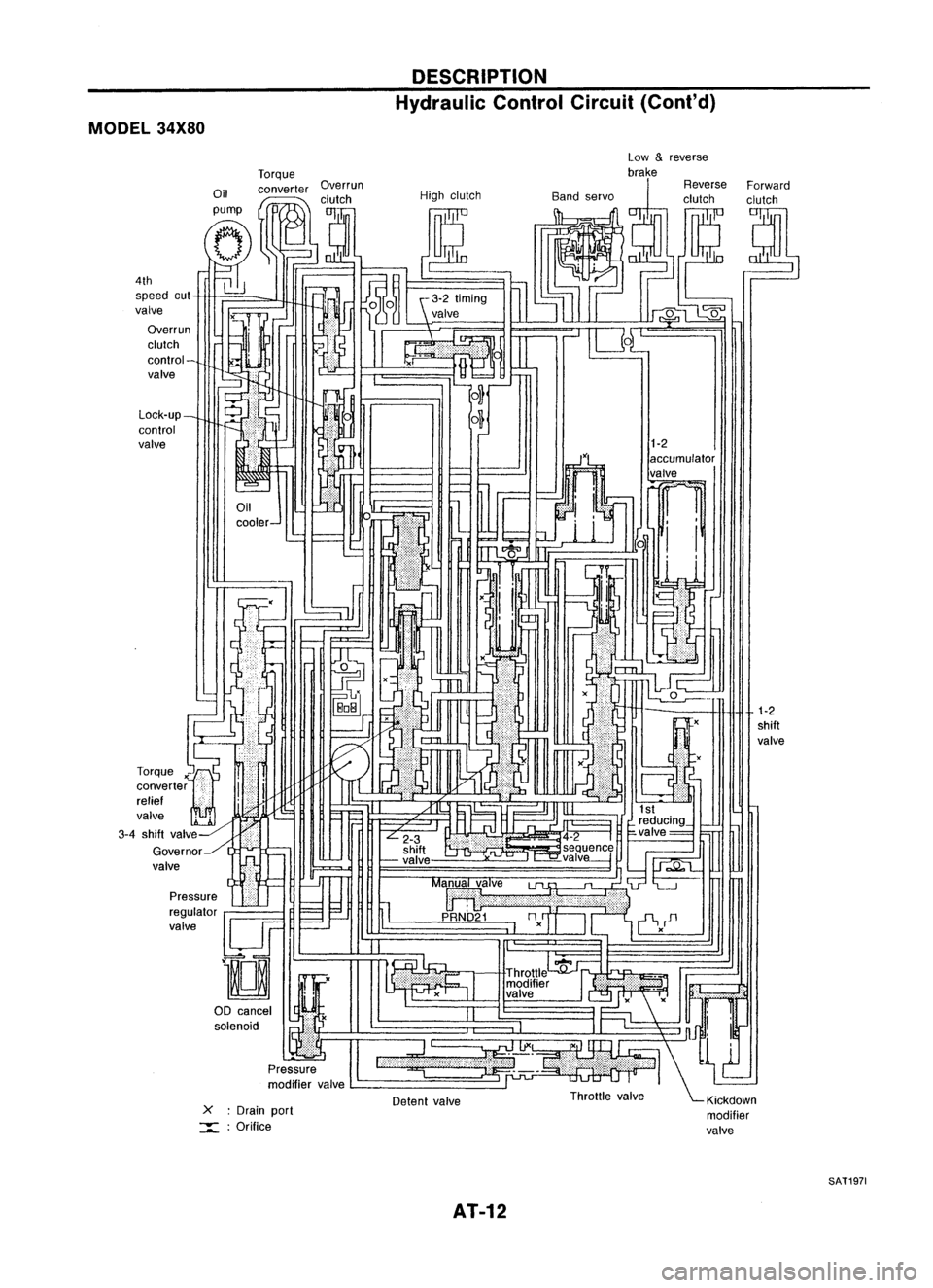
Hydraulic ControlCircuit(Cont'd)
MODEL 34X80
1-2
shift
valve
1-2
accumulator
valve
~ 1
i i
xU
::l.
x
-
Detent valve
L-
_
-
cooler- Low
&
reverse
Torque brake
Oil converter Overrun ReverseForward
I
,clutch Highclutch Bandservo clutchclutch
pump
I
tJ
(Jp::-
(T,
tf1
--;::;-;r.]O~
~J
1~
g~ (~ ~~
l]
J~ ~
~iJ -
N
~%~
UL"-'
IU4~1~~
C-1
-!
~frEJ!
1
6 ~, -~
m
~,--J
0
- ILJ
,-O...J
r
ar
r::r=< I'---,
II .(
I'
IJ
,'-
~
,,'
(
-
I -
=-
~tL ',
~H
I~
~ ~M~ ·
F=
f='l .,.11
1-
~I" ~
" ~r'
I
L...---...l
reducing_
L
2-3 .4-2
I
~valve= ~
shift ~seq!!.enc~
~ -valve ,-=-valve---j
h
1J;;;.Q"t....
=--=-.J
II
Ma~alve
lJl.
"~'L--.J
:;;; ~I 11
p
URNb'21
nn
=-.--'
I~
II
'i-V
D
I I -,
." c:
I
Throttle
':fj'~1 .
modifier
If.'
valve .
II
I
1"
";'Jnn!
l...,
:=~-' \~
Throttle valve ~Klckdown
modifier
valve
X
:Drain port
:::::: :Orifice
Pressure
regulator
valve
!lJF
D
00 cancel
I
~Y&
solenoid •
Pressure
modifier valve
Lock-up_
control
valve
4th
speed cut
valve
Overrun
clutch
control-
valve
-=~
I
r
rr=-
LL:
J~
L~
Torque
x'"~
converter
i
i
relief '
valve
2~ '-
3-4 shift valv~-HiliJI
Governor../l ..-
valve
SAT1971
AT-12
Page 18 of 1701

SAT497GTROUBLE
DIAGNOSES
Road Testing (Cont'd)
"0"
POSITION
1. Manually moveselector leverfrom"N"to"D" position, and
note shiftquality.
2. Using theshift schedule asareference, drivevehicle in"D"
position. Record,onsymptom chart,respective vehicle
speeds atwhich up-shifting anddown-shifting occur.These
speeds aretobe read atthree different throttlepositions
(light, halfandfull), respectively. Alsodetermine thetiming
at which shocks areencountered duringshifting andwhich
clutches areengaged.
SAT612GA
3.Determine whetherlock-upproperly occurswhiledriving
vehicle inproper gearposition andatproper vehicle speed.
4. Check todetermine ifshifting tooverdrive gearcannot be
made whileODcontrol switchis"OFF".
5. Drive vehicle in"D
3"
position athalf tolight throttle posi-
tion. Keep driving at60 to70 km/h (34to43 MPH). FUlly
depress accelerator pedaltomake suretransaxle down-
shifts from3rdto2nd gear.
6. Drive vehicle in"D
2"
position athalf tolight throttle posi-
tion. Keep driving at25 to35 km/h (16to22 MPH). Fully
depress accelerator pedaltomake suretransaxle down-
shifts from2ndto1st gear.
"2"
POSITION
1. Shift to"2" position andmake surevehicle startsin1st
gear.
2. Increase vehiclespeedtomake suretransaxle upshiftsfrom
1st to2nd gear.
3. Further increase vehiclespeed.Makesuretransaxle does
not upshift to3rd gear.
4. Drive vehicle in"2
2"
position athalf tolight throttle position.
Keep driving at25 to35 km/h (16to22 MPH). Fullydepress
accelerator pedaltomake suretransaxle downshifts from
2nd to1st gear.
5. Allow vehicle torun idle while in"2" position tomake sure
that transaxle downshifts to1st gear.
6. Move selector leverto"D" position andallow vehicle to
operate at30 to40 km/h (19to25 MPH). Then,shiftto"2"
position tomake suretransaxle downshifts to2nd gear.
"1"
POSITION
1. Place selector leverin"1" position andaccelerate vehicle.
Make suretransaxle doesnotshift from 1stto2nd gear
although vehiclespeedincreases.
2. Drive vehicle in"1" position. Releaseaccelerator pedalto
make surethatengine compression actsasabrake.
3. Place selector leverin"D" or"2" position andallow vehi-
cle torun at15 to25 km/h (9to 16 MPH). Thenmove selec-
tor lever to"1" position tomake suretransaxle downshifts
to 1st gear.
AT-18
Page 19 of 1701
TROUBLEDIAGNOSES
Road Testing (Cont'd)
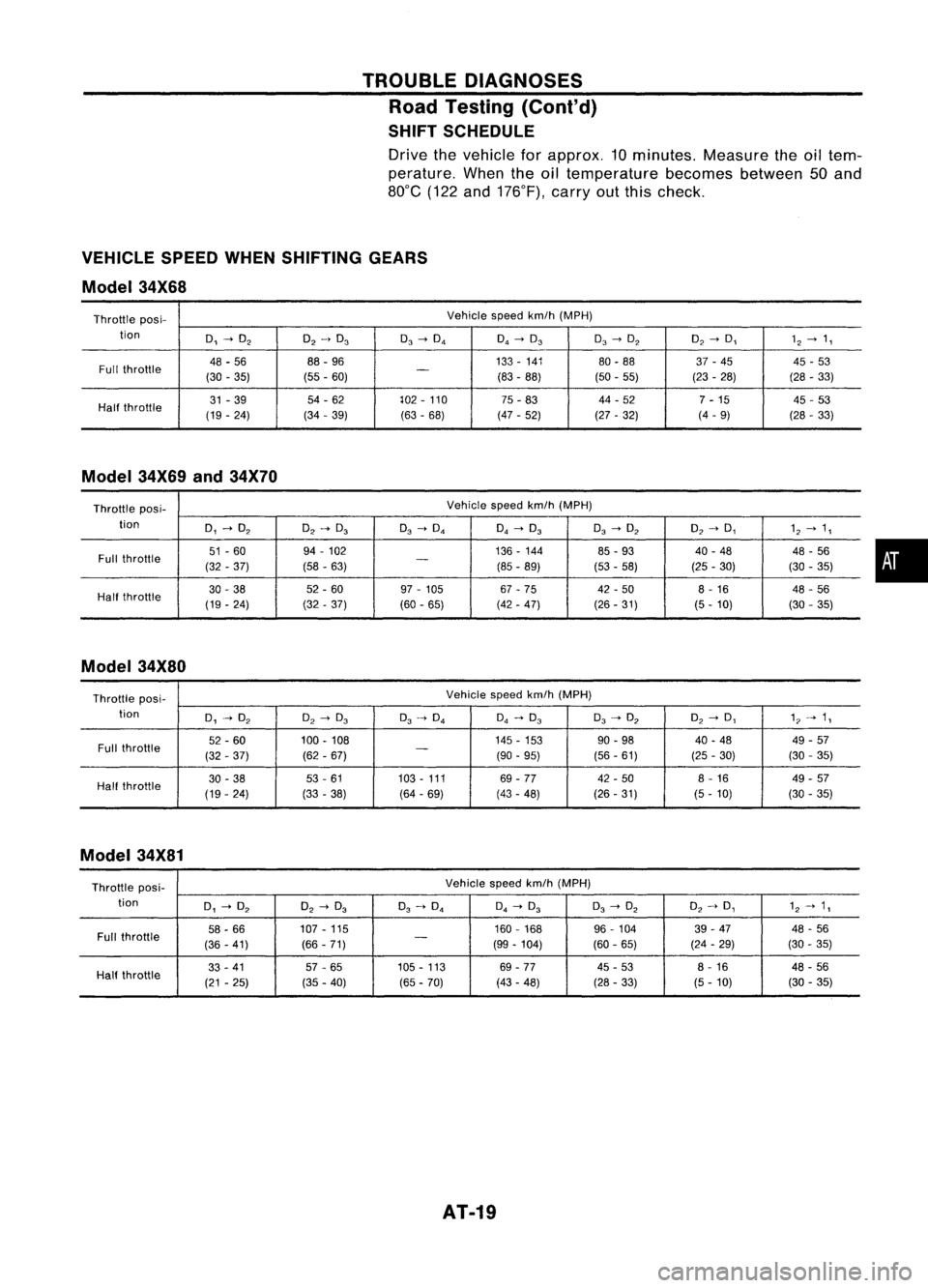
SHIFT SCHEDULE
Drive thevehicle forapprox. 10minutes. Measuretheoiltem-
perature. Whentheoiltemperature becomesbetween50and
80°C (122and176°F), carryoutthis check.
VEHICLE SPEEDWHENSHIFTING GEARS
Model 34X68
Throttle posi- Vehicle
speedkm/h(MPH)
tion
0,~O
2
O
2
->
0
3
0
3
->
0
4
0
4
~
0
3
0
3
->
O
2
O
2
->
0,
1
2
~
1,
Full throttle
48
-56 88
-96 133
-141
80-88 37-45 45-53
(30 -35) (55-60)
-
(83-88)
(50-55) (23-28) (28
-33)
Half throttle
31
-39 54
-62 102-110
75-83 44
-52
7-15 45
-53
(19 -24) (34
-39)
(63-68) (47
-52)
(27-32) (4
-9)
(28-33)
Model 34X69and34X70
Throttle pas
i-
Vehicle
speedkm/h(MPH)
tion
0,~O
2
O
2~
0
3
0
3
->
0
4
0
4~
0
3
0
3
->
O
2
O
2~
0,
1
2~
1,
Full throttle
51
-60 94
-102 136-144
85-93 40
-48
48-56
(32 -37) (58-63)
-
(85-89)
(53-58) (25
-30) (30-35)
Half throttle
30
-38 52
-60 97-105 67-75 42-50 8-16
48-56
(19 -24) (32-37) (60-65) (42-47) (26-31) (5-10) (30-35)
Model 34X80
Throttle posi- Vehicle
speedkm/h(MPH)
tion
0,~O
2
O
2
->
0
3
0
3~
0
4
0
4
->
0
3
0
3
~
O
2
O
2
->
0,
1"
->
1,
Full throttle
52
-60 100-108 145
-153
90-98 40
-48 49-57
(32 -37) (62-67)
-
(90-95) (56-61) (25-30) (30
-35)
Half throttle
30
-38 53-61 103
-111
69-77 42
-50 8-16 49-57
(19 -24) (33-38) (64-69) (43-48) (26-31) (5-10) (30-35)
Model 34X81
Throttle posi- Vehicle
speedkm/h(MPH)
tion
0,~O
2
O
2
->
0
3
0
3
~
0
4
0
4
->
0
3
0
3
->
O
2
O
2
~
0,
1
2~
1,
Full throttle
58
-66 107
-115 160
-168
96-104 39
-47 48-56
(36 -41) (66
-71)
-
(99-104) (60-65) (24
-29) (30
-35)
33 -41 57-65 105
-113 69-77 45-53 8-16 48-56
Half throttle
(21-25) (35-40)
(65-70) (43
-48) (28-33) (5-10) (30
-35)
AT-19
•
Page 24 of 1701
TROUBLEDIAGNOSES
Stall Tasting
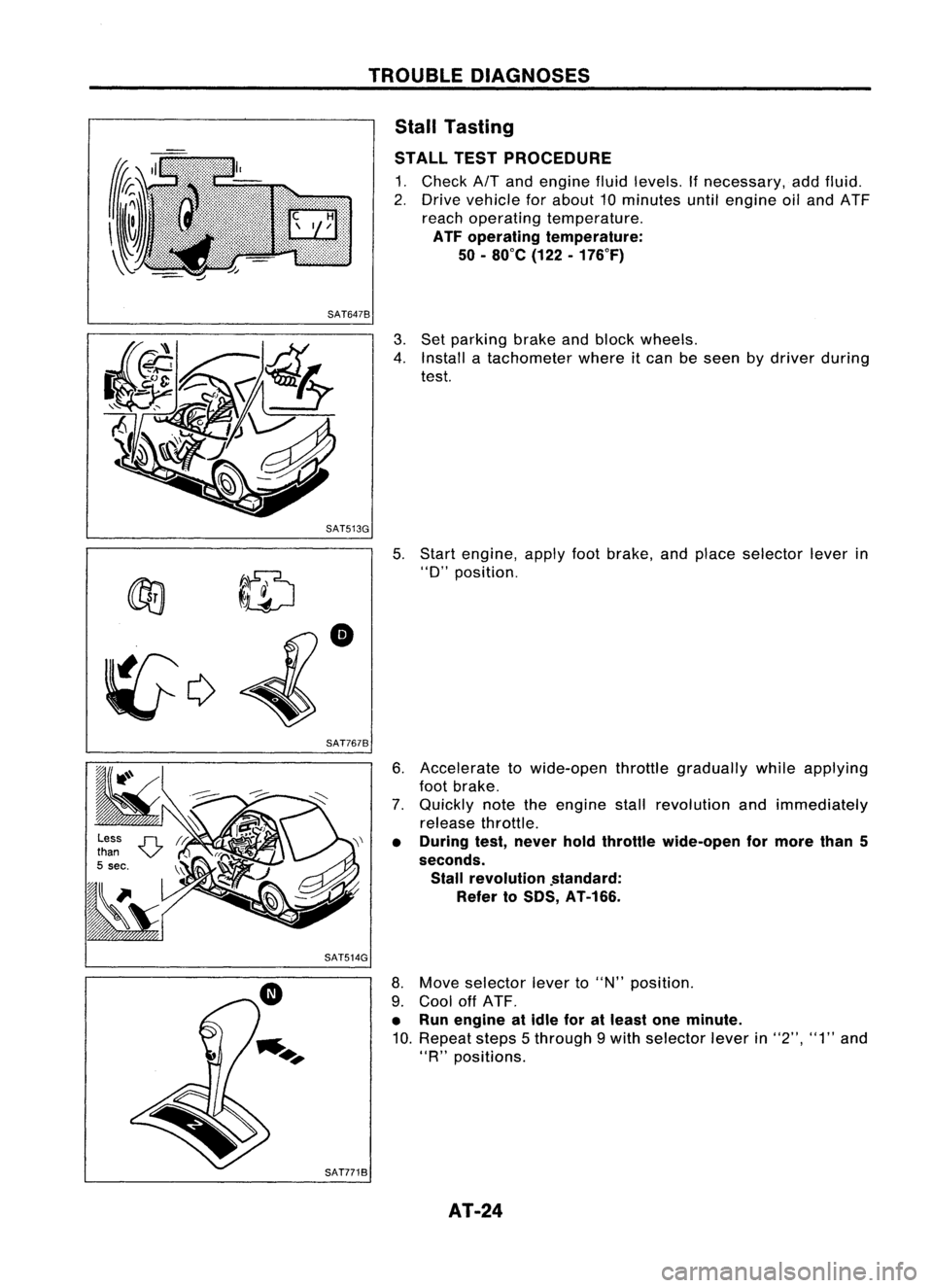
STALL TESTPROCEDURE
1. Check
AIT
and engine fluidlevels. Ifnecessary, addfluid.
2. Drive vehicle forabout 10minutes untilengine oiland ATF
reach operating temperature.
ATF operating temperature:
50 -80
0
e (122-176°F)
SAT6478
3.Set parking brakeandblock wheels.
4. Install atachometer whereitcan beseen bydriver during
test.
SAT513G 5.
~ ~ID
•
~c;>
SAT7678
Start
engine, applyfootbrake, andplace selector leverin
"0"
position.
6. Accelerate towide-open throttlegradually whileapplying
foot brake.
7. Quickly notetheengine stallrevolution andimmediately
release throttle.
• During test,never holdthrottle wide-open formore than5
seconds. Stall revolution .standard:
Refer toSDS, AT-166.
SAT514G
8.Move selector leverto"N" position.
9. Cool offATF.
• Run engine atidle foratleast oneminute.
10. Repeat steps5through 9with selector leverin"2", "1"and
"R
n
positions.
SAT7718 AT-24
Page 26 of 1701
TROUBLEDIAGNOSES
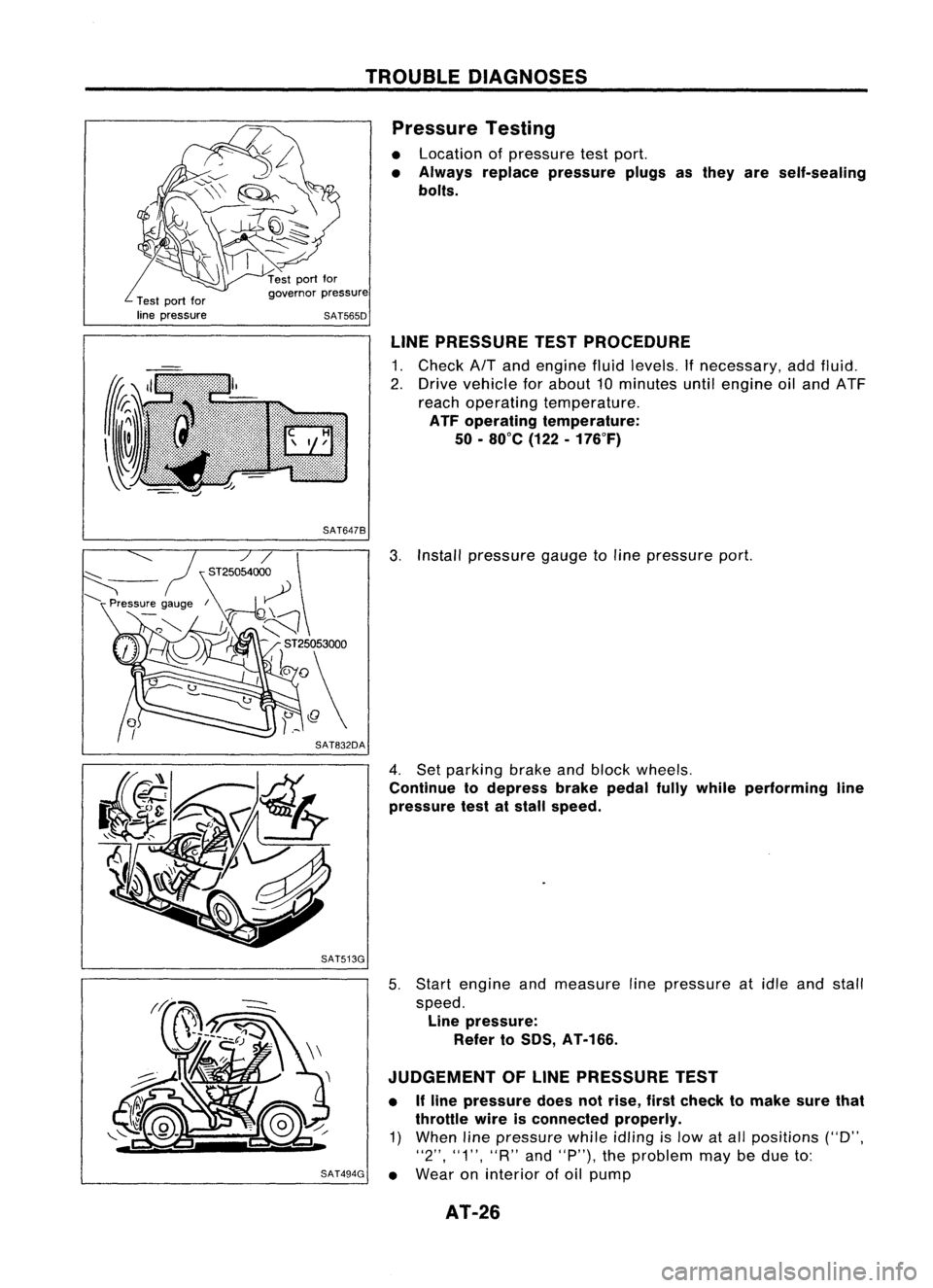
Pressure Testing
• Location ofpressure testport.
• Always replace pressure plugsasthey areself-sealing
bolts.
Test portfor
line pressure governor
pressure
SAT565D
LINEPRESSURE TESTPROCEDURE
1. Check AfTand engine fluidlevels. Ifnecessary, addfluid.
2. Drive vehicle forabout 10minutes untilengine oiland ATF
reach operating temperature.
ATF operating temperature:
50 -80°C (122-176°F)
SAT647B
3.Install pressure gaugetoline pressure port.
4. Set parking brakeandblock wheels.
Continue todepress brakepedalfullywhile performing line
pressure testatstall speed.
SAT513G
5.Start engine andmeasure linepressure atidle and stall
speed. Line pressure:
Refer toSOS, AT-166.
JUDGEMENT OFLINE PRESSURE TEST
• Ifline pressure doesnotrise, firstcheck tomake surethat
throttle wireisconnected properly.
1) When linepressure whileidling
is
low atall positions ("D",
"2", "1", "R"and"P"), theproblem maybedue to:
SAT494G •
Wear oninterior ofoil pump
AT-26
Page 33 of 1701
ON-VEHICLESERVICE
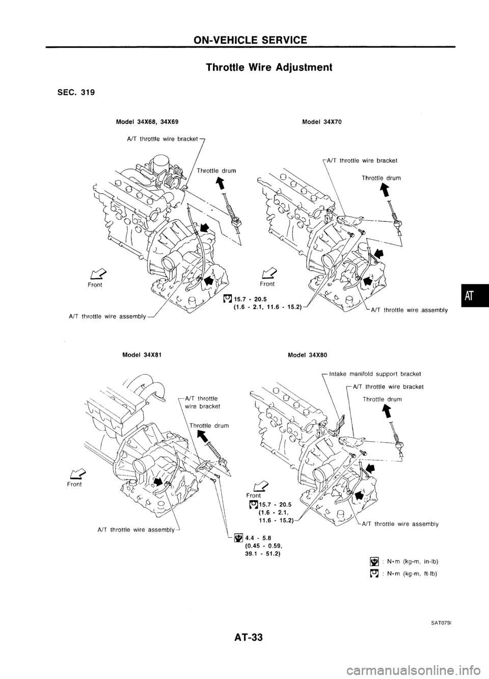
Throttle WireAdjustment
SEC. 319
Model34X68, 34X69
AIT
throttle wirebracket
Front
AIT
throttle wireassembly
Model 34X81 Model
34X70
Model 34X80
•
Front
AIT
throttle wireassembly
(0.45-0.59,
39.1 -51.2)
AT-33 Intake
manifold supportbracket
NT throttle wirebracket
Throttle drum
iii :
N.m (kg-m, in-Ib)
~ :N.m (kg-m, ft-Ib)
SAT0791