Page 34 of 1701

p,
(Full throttle position)
~ThrOttle drum
Direction U
, ,-- p,
t
I ~.
(Idling
--r ~_ .)
position)
I
Direction T
Engine side\"
bracket (at
P,)
~ Adjusting tube
Lock plate ON-VEHICL")
(atP,)
p,
(Full throttle position)
~ThrOttle drum
Direction U
, ,-- p,
t
I ~.
(Idling
--r ~_ .)
position)
I
Direction T
Engine side"
bracket (at
P,)
~ Adjusting tube
Lock plate ON-VEHICLE
SERVICE
Throttle WireAdjustment (Cont'd)
1. Turn ignition switchtoOFF.
2. While pressing lockplate, moveadjusting tubeindirection
"T" (Transaxle side).
3. Return lockplate.
(Adjusting tubeislocked atthis time.)
4. Move throttle drumfrom
"P2"
to
"P
1"
quickly. Adjusting
tube moves indirection "U"(Engine side)while depressing
the lock plate. Ensure thatthrottle wirestroke "L"iswithin
the specified range,between fullthrottle andidle.
Throttle wirestroke "L":
40 -42
mm
(1.57 -1.65
in)
• Adjust throttle wirestroke afteraccelerator wireisinstalled
and adjusted.
• When connecting throttlewiretothrottle drum,donot use
tools. Manually hookit.
• Put mark onthrottle wiretofacilitate measuring wirestroke.
5. Clamp throttle wireatproper positions showninthe illus-
tration afteradjusting throttlewire.
6. After properly adjusting andclamping throttlewire,ensure
the parting lineisas straight aspossible.
SAT551D
4/4
Vehiclespeed
If
throttle wirestroke isimproperly adjustedthefollowing prob-
lems mayarise.
• "P
1"
isthe throttle drumfully-open position.When"P
1"
is
too farindirection
"T",
theshift schedule willbe
@
inthe
figure. Andthekickdown rangewillgreatly increase.
• When
"P1"
istoo farindirection "U",theshift schedule will
be
CD
inthe figure. Andthekickdown willnotoccur.
SAT669H
I
I
Normal :
,- .J
,/
/
,,~/~
/
---------1--
,/
'//
r-/
I
I
o
0>
c:
C
Q)
0-
o
~
2
£
I-
AT-34
Page 39 of 1701
REMOVALANDINSTALLATION
Removal
• Remove batteryandbracket.
• Remove airduct.
• Disconnect
AIT
solenoid harnessconnector, inhibitorswitch
harness connector andspeedometer pinionharness con-
nector.
• Disconnect throttlewireatengine side.
• Drain ATF.
• Remove undercover andside cover.
• Disconnect controlcablefromtransaxle.
• Disconnect oilcooler hoses.
• Remove driveshafts -Refer toFA section ("Removal", •
"FRONT AXLE-Drive Shaft").
• Remove exhaustfronttube.
• Remove startermotorfromtransaxle.
• Remove frontandrear gussets andengine rearplate.
• Remove boltssecuring torqueconverter todrive plate.
Rotate crankshaft foraccess tosecuring bolts.
• Support enginebyplacing ajack under oilpan.
Do not place jackunder oilpan drain plug.
• Support transaxle withajack.
• Remove LHand rear mountings fromtransaxle.
• Remove boltsfixing
AIT
toengine.
• Lower transaxle whilesupporting
it
with ajack.
AT-39
Page 41 of 1701
Boltlength
'T'
mm (in)
55 (2.17)
50 (1.97)
65 (2.56)
25 (0.98)
40 (1.57)
Tightening
torque
N'm (kg-m, ft-Ib)
70 -79 (7.1 -8.1,51 -59)
70 -79 (7.1 -8.1, 51-59)
70 -79 (7.1 -8.1,51 -59)
30 -40 (3.1 -4.1, 22-30)
30 -40 (3.1 -4.1, 22-30)
CD
@
@
@
@
Bolt
No.
• Reinstall anypart removed.
• Adjust throttle wireandcontrol cable.Referto"ON-VEHI-
CLE SERVICE", AT-33,35.
•. Check inhibitor switch.Referto"Electrical Components
Inspection", AT-3D.
• Refill transaxle withATFandcheck fluidlevel, AT-17.
• Move selector leverthrough allpositions tobe sure that
transaxle operatescorrectly. Withparking brakeapplied,
idle engine. Moreselector leverthrough "N"to"D", to"2",
to "1" and "R". Aslight shock should befelt through the
hand gripping theselector eachtimethetransaxle is
shifted. •
• Perform roadtest-Refer to"ROAD TESTING", AT-17.
i
REMOVAL
ANDINSTAllATION
Installation (Cont'd)
SR engine models
SAT638A
SAT558DA
AIT
toengine
@
Engine to
AIT
AT-41
Page 54 of 1701
DISASSEMBLV
21. Remove throttlewirefrom throttle lever.
22. Remove throttlewiremounting bolt.
23. Draw outthrottle wirefrom transmission case.
- All models -
24. Remove converter housingaccording tothe following pro-
cedures.
a. Remove converter housingmounting bolts@and
CID.
b. Remove converter housing.
c. Remove O-ringfromdifferential oilport.
AT-54
Page 66 of 1701
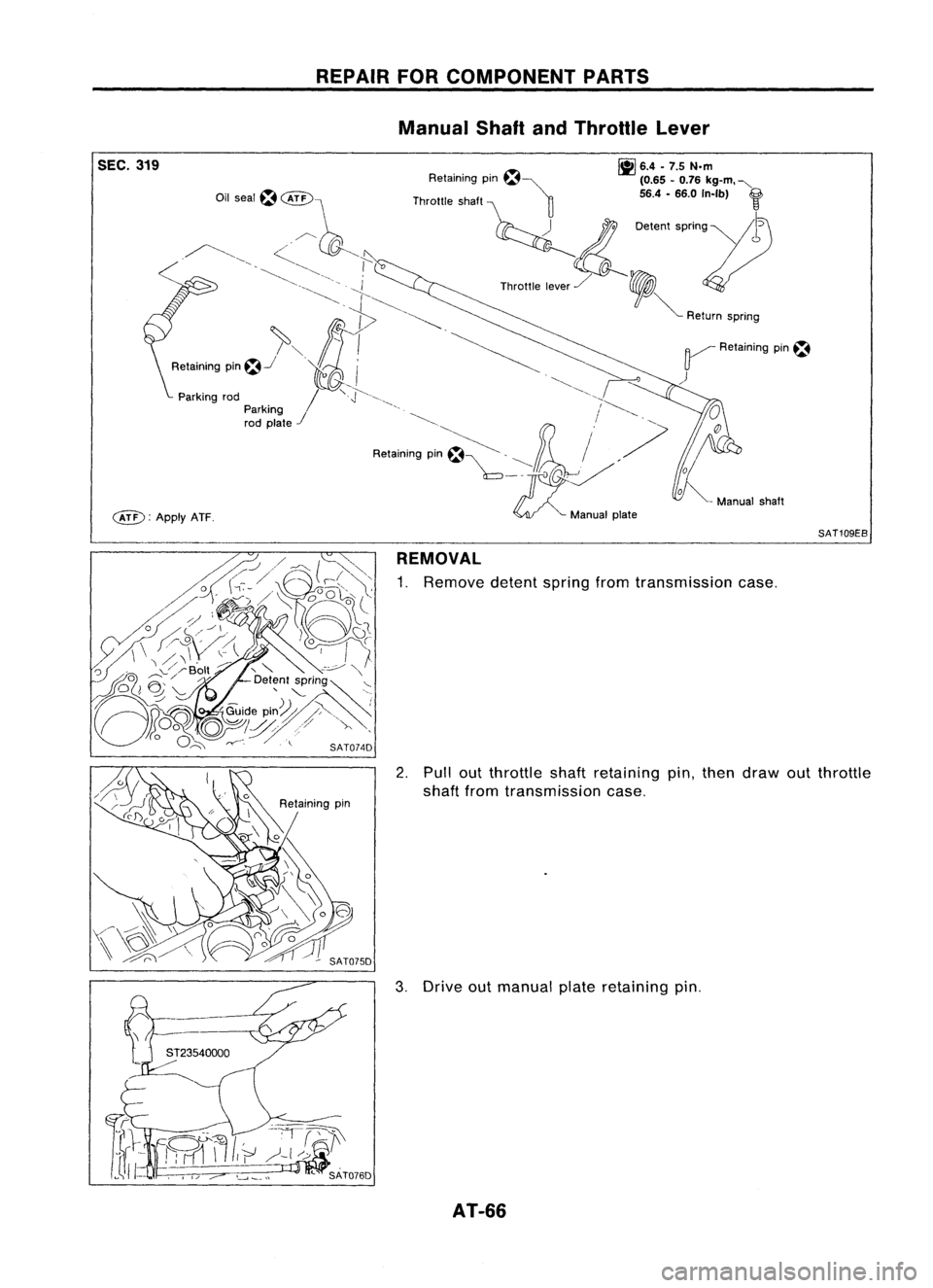
SEC.319
c&D:
ApplyATF. REPAIR
FORCOMPONENT PARTS
Manual ShaftandThrottle Lever
~ 6.4•7.5 N.m
Retaining pm~~ (0.65-0.76 kg-m. "-
Throttle shaft ~ 56.4-66.0 In-Ib)
f
~ 0.""
''''0'''11)
Th""'. ,,~,/ ,
V
~ Return spnng
~ Retaining pin~
)
SAT109EB
REMOVAL
1. Remove detentspringfromtransmission case.
2. Pullout throttleshaftretaining pin,then draw outthrottle
shaft fromtransmission case.
3. Drive outmanual plateretaining pin.
AT-66
Page 67 of 1701
REPAIRFORCOMPONENT PARTS
Manual ShaftandThrottle Lever(ConI'd)
4. Drive andthen pulloutparking rodplate retaining pin.
5. Remove parkingrodplate frommanual shaft.
6. Draw outparking rodfrom transmission case.
7. Pull outmanual shaftretaining pin. •
8. Remove manualshaftandmanual platefromtransmission
i
case.
9. Remove manualshaftoilseal.
SATOBOD
INSPECTION
• Check component partsforwear ordamage. Replaceif
necessary.
AT-67
Page 68 of 1701
REPAIRFORCOMPONENT PARTS
Manual ShaftandThrottle Lever(Cont'd)
INSlALLA liON
1. Install manual shaftoilseal.
• Apply ATFtoouter surface ofoil seal.
2. Install throttle leverandreturn spring onthrottle shaft.
3. Install throttle leverassembly ontransmission case.
4. Align groove ofthrottle shaftandhole oftransmission case.
5. Install throttle shaftretaining pin.
6. Move throttle leverinthe direction ofthe arrow.
7. Install manual shaftandmanual plate.
8. Align groove ofmanual shaftandhole oftransmission case.
9. Install manual shaftretaining pin.
AT-68
Page 69 of 1701
•
12.
Install manual plateretaining pinand parking rodplate
retaining pin.
13. Install detent spring.
SAT087D
REPAIR
FORCOMPONENT PARTS
Manual ShaftandThrottle Lever(Cont'd)
10. Install parking rodtoparking rodplate.
11. Install parking rodassembly tomanual shaft.
View A
Retaining Pin~
Manual plate
and parking
(rod plate
" ~5 .6
mm
- (0.20 •0.24 In)
tt
~ /1
ST2354~
~~
Parking
rodplate
AT-69


55 (2.17)
50 (1.97)
65 (2.56)
25 (0.98)
40 (1.57)
Tightening
torque
N'm (kg-m, ft-Ib)
70 -79 (7.1 -8.1,51 -59)
70 -79 (7.1 -8.1, 51-59)
70 -79 (7.1 -8.1,51 -59")


4. Drive andthen pulloutparking rodplate retaining pin.
5. Remove parkingrodplate frommanual shaft.
6. Draw outparking rodfrom trans")

INSlALLA liON
1. Install manual shaftoilseal.
• Apply ATFtoouter surface ofoil seal.
2. Install throttle leverandreturn spring")

10. Install park")