1995 NISSAN ALMERA N15 Throttle
[x] Cancel search: ThrottlePage 756 of 1701
SEF217M
•
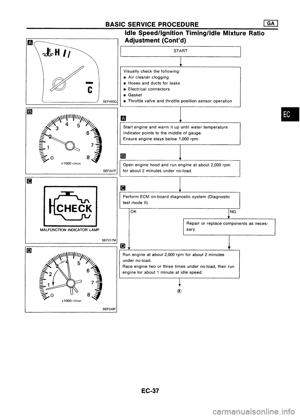
START
Visually checkthefollowing:
• Air cleaner clogging
• Hoses andducts forleaks
• Electrical connectors
• Gasket
• Throttle valveandthrottle position sensoroperation
m
Start engine andwarm itup until water temperature
indicator pointstothe middle ofgauge.
Ensure enginestaysbelow 1,000rpm.
iii
Open engine hoodandrunengine atabout 2,000rpm
for about 2minutes underno-load.
[iJ
Perform ECMon-board diagnostic system(Diagnostic
test mode II).
OK lNG
Repair orreplace components asneces-
sary.
I!]
1
Run engine atabout 2,000rpmforabout 2minutes
under no-load.
Race engine twoorthree times under no-load, thenrun
engine forabout 1minute atidle speed.
~
BASIC
SERVICE PROCEDURE
eM]
Idle Speed/Ignition Timing/IdleMixtureRatio
Adjustment (Cont'd)
SEF247F
SEF455Q
MALFUNCTION INDICATORLAMP
SEF248F
EC-37
Page 757 of 1701
l
Ii
1)
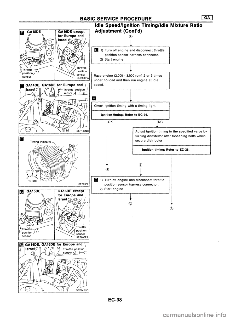
Turn offengine anddisconnect throttle
position sensorharness connector.
2) Start engine.
Race engine (2,000-3,000 rpm)2or 3times
under no-load andthen runengine atidle
speed.
Ii
Check ignition timingwithatiming light.
Ignition timing:RefertoEC-36.
OK
lNG
Adjust ignition timingtothe specified valueby
turning distributor afterloosening boltswhich
secure distributor.
Ignition timing:RefertoEC-36.
(])
@
l
[!1
1)Turn offengine anddisconnect throttle
position sensorharness connector.
2) Start engine.
~
@
BASIC
SERVICE PROCEDURE
@]
Idle Speed/Ignition Timing/ldleMixtureRatio
Adjustment (Cont'd)
@
SEF695L EC-38
Page 758 of 1701
BASICSERVICE PROCEDURE @KJ
Idle Speed/Ignition Timing/IdleMixtureRatio
Adjustment (Cont'd)
1
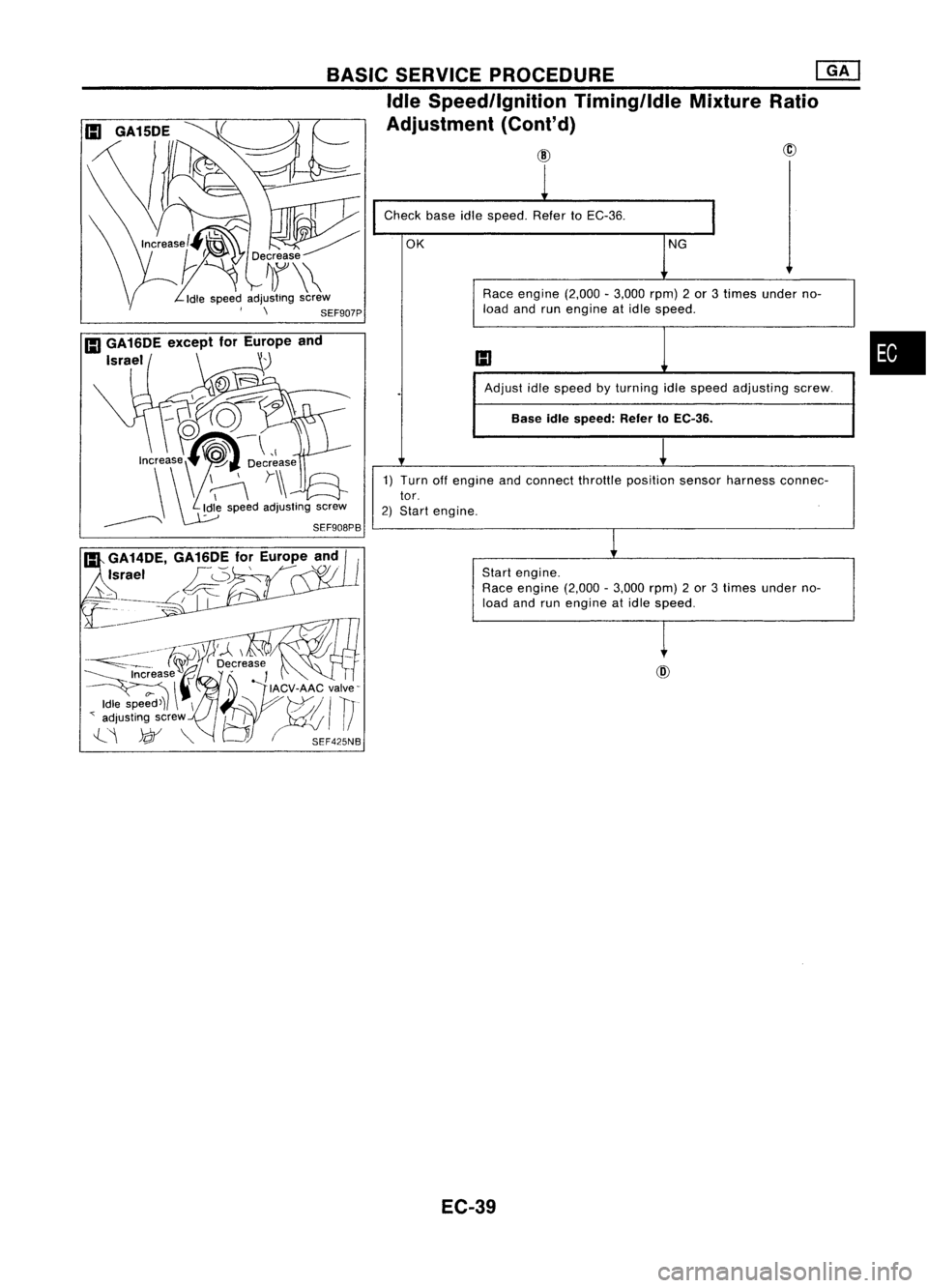
Check baseidlespeed. RefertoEC-36.
I
OK
NG
Race engine (2,000-3,000 rpm)2or 3times under no-
load andrunengine atidle speed.
III
.
Adjust
idlespeed byturning idlespeed adjusting screw.
Base idlespeed: RefertoEC-36.
1) Turn offengine andconnect throttleposition sensorharness connec-
tor.
2) Start engine.
1
Start engine.
Race engine (2,000-3,000 rpm)2or 3times under no-
load andrunengine atidle speed.
t
EC-39
•
Page 765 of 1701
ON-BOARDDIAGNOSTIC SYSTEMDESCRIPTION @KJ
Malfunction Indicatorlamp(Mil)(Cont'd)
DIAGNOSTIC TESTMODE I-BULB CHECK
In this mode, theMALFUNCTION INDICATORLAMPonthe instrument panelshould stayON.Ifitremains
OFF, check thebulb. Refer toEL section ("WARNING LAMPSANDCHIME") orsee EC-223.
DIAGNOSTIC TESTMODE I-MALFUNCTION WARNING
MALFUNCTION INDICATORLAMP
ON
OFF Condition
Engine coolant temperature sensorcircuitmalfunction oroverheating isdetected, or
the ECM's CPUismalfunctioning.
No malfunction.
• These Diagnostic TroubleCodeNumbers areclarified inDiagnostic TestMode II(SELF-DIAGNOS-
TIC RESULTS).
DIAGNOSTIC TESTMODE II-SELF-DIAGNOSTIC RESULTS
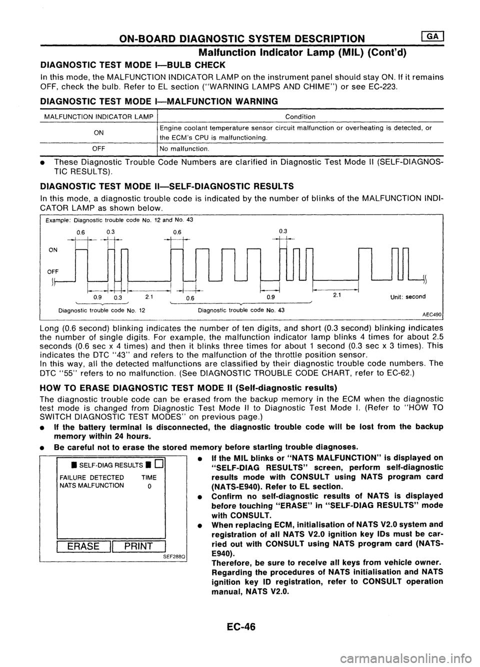
In this mode, adiagnostic troublecodeisindicated bythe number ofblinks ofthe MALFUNCTION INDI-
CATOR LAMPasshown below.
Example: Diagnostic troublecodeNo.12and No.43
ON
0.6
03
111-'1
0.6
II
0.3
OFF
j
~
~~ -I.
--.1
-4--1--
Q9 O~ 21 OB Q9
'--------v----' '--------v------~
Diagnostic troublecodeNo.12 DiagnostictroublecodeNo.43
2.1
Unit:second
AEC490
• SELF-DIAG RESULTS.
0
FAILURE DETECTED TIME
NATS MALFUNCTION
0
I
ERASE
II
PRINT
I
SEF288Q
Long
(0.6second) blinkingindicates thenumber often digits, andshort (0.3second) blinkingindicates
the number ofsingle digits. Forexample, themalfunction indicatorlampblinks 4times forabout 2.5
seconds (0.6secx4 times) andthen itblinks threetimes forabout 1second (0.3secx3 times). This
indicates theDTC "43" andrefers tothe malfunction ofthe throttle position sensor.
In this way, allthe detected malfunctions areclassified bytheir diagnostic troublecodenumbers. The
DTC "55" refers tono malfunction. (SeeDIAGNOSTIC TROUBLECODECHART, refertoEC-62.)
HOW TOERASE DIAGNOSTIC TESTMODE II(Self-diagnostic results)
The diagnostic troublecodecanbeerased fromthebackup memory inthe ECM when thediagnostic
test mode ischanged fromDiagnostic TestMode IIto Diagnostic TestMode
I.
(Refer to"HOW TO
SWITCH DIAGNOSTIC TESTMODES" onprevious page.)
• Ifthe battery terminal isdisconnected, thediagnostic troublecodewillbelost from thebackup
memory within24hours.
• Becareful nottoerase thestored memory before
startin~
troublediagnoses.
• If
the MIL blinks or"NATS MALFUNCTION" isdisplayed on
"SELF-OIAG RESULTS"screen,perform self-diagnostic
results modewithCONSULT usingNATS program card
(NATS-E940). RefertoEL section.
• Confirm noself-diagnostic resultsofNATS isdisplayed
before touching "ERASE" in"SELF-DIAG RESULTS"mode
with CONSULT.
• When replacing ECM,initialisation ofNATS V2.0system and
registration ofall NATS V2.0ignition key10smust becar-
ried outwith CONSULT usingNATS program card(NATS-
E940).
Therefore, besure toreceive allkeys from vehicle owner.
Regarding theprocedures ofNATS initialisation andNATS
ignition key10registration, refertoCONSULT operation
manual, NATS V2.0.
EC-46
Page 768 of 1701
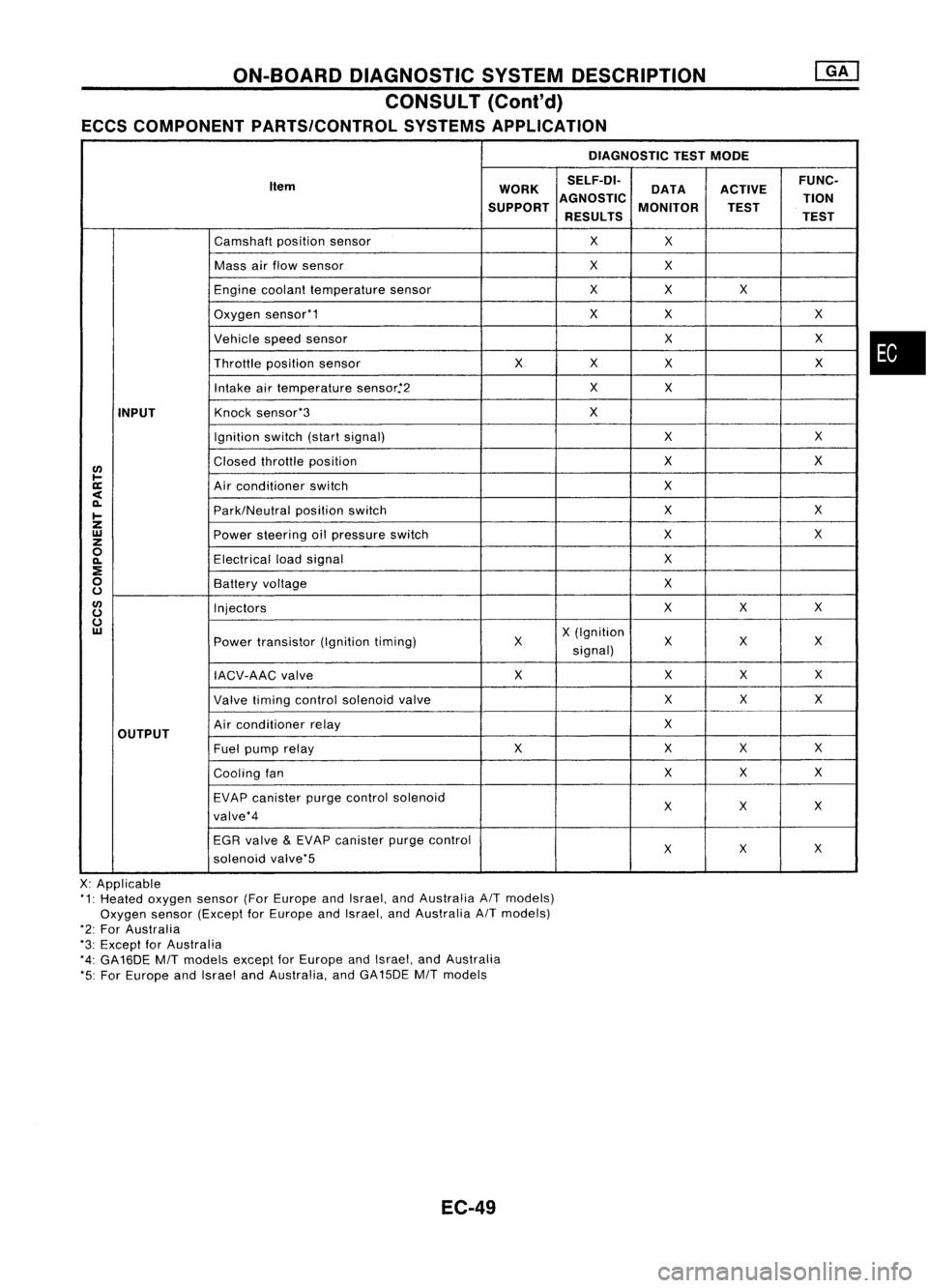
ON-BOARDDIAGNOSTIC SYSTEMDESCRIPTION
CONSULT (Cont'd)
ECCS COMPONENT PARTS/CONTROL SYSTEMSAPPLICATION
DIAGNOSTICTESTMODE
Item WORKSELF-DI-
ACTIVEFUNC-
DATA
SUPPORT AGNOSTIC
MONITOR TION
TEST
RESULTS TEST
Camshaft positionsensor
X
X
Mass airflow sensor
X
X
Engine coolant temperature sensor
X
X X
Oxygen sensor'1
X
X X
Vehicle speedsensor
XX
Throttle positionsensor
XX
X X
Intake airtemperature sensor.'2
X
X
INPUT
Knock
sensor'3
X
Ignition switch(startsignal)
XX
I/)
Closed
throttle position
X
X
l-
ll:
Airconditioner switch
X
<
~
Park/Neutralpositionswitch
X
X
I-
Z
UJ
Powersteering oilpressure switch
XX
z
0
Electricalloadsignal
X
~
:E
0
Batteryvoltage
X
u
I/)
Injectors
XX
X
u
u
UJ
X(Ignition
Power transistor (Ignitiontiming) X X
XX
signal)
IACV-AAC valve X
XX
X
Valve timing control solenoid valve XX
X
OUTPUT
Air
conditioner relay
X
Fuel pump relay XX
XX
Cooling fan XX
X
EVAP canister purgecontrol solenoid
XX X
valve'4
EGR valve
&
EVAP canister purgecontrol
XX
X
solenoid valve'5
X: Applicable
'1: Heated oxygen sensor(ForEurope andIsrael, andAustralia AITmodels)
Oxygen sensor(Except forEurope andIsrael, andAustralia AITmodels)
'2: For Australia
'3: Except forAustralia
'4: GA16DE
MIT
models exceptforEurope andIsrael, andAustralia
'5: For Europe andIsrael andAustralia, andGA15DE
MIT
models
EC-49
•
Page 769 of 1701
ON-BOARDDIAGNOSTIC SYSTEMDESCRIPTION
CONSULT (Cont'd)
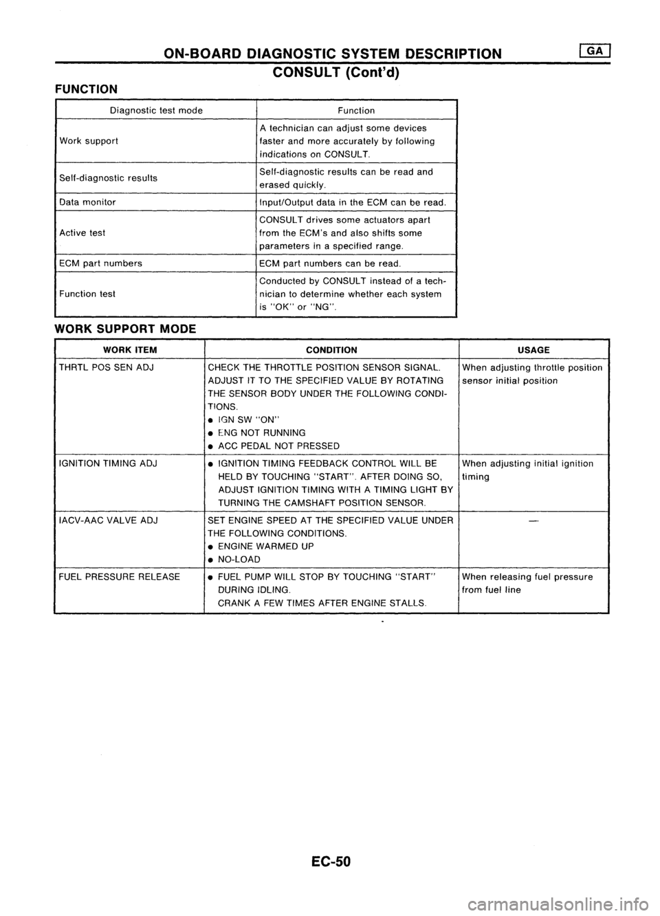
FUNCTION
Diagnostictestmode
Function
A technician canadjust somedevices
Work support
fasterandmore accurately byfollowing
indications onCONSULT.
Self-diagnostic results Self-diagnostic
resultscanberead and
erased quickly.
Data monitor
Input/Outputdatainthe ECM canberead.
CONSUL Tdrives someactuators apart
Active test
fromtheECM's andalso shifts some
parameters inaspecified range.
ECM partnumbers ECMpartnumbers canberead.
Conducted byCONSULT insteadofatech-
Function test
niciantodetermine whethereachsystem
is "OK" or"NG".
WORK SUPPORT MODE
WORK ITEM
CONDITION USAGE
THRTL POSSENADJ
CHECKTHETHROTTLE POSITIONSENSORSIGNAL. Whenadjusting throttleposition
ADJUST iTTO THE SPECIFIED VALUEBYROTATING
sensorinitialposition
THE SENSOR BODYUNDER THEFOLLOWiNG CONDI-
TIONS .
• IGN SW"ON"
• ENG NOTRUNNING
• ACC PEDAL NOTPRESSED
IGNITION TIMINGADJ
•IGNITION TIMINGFEEDBACK CONTROLWILLBE Whenadjusting initialignition
HELD BYTOUCHING "START".AFTERDOINGSO,
timing
ADJUST IGNITION TIMINGWITHATIMING LIGHTBY
TURNING THECAMSHAFT POSITIONSENSOR.
IACV-AAC VALVEADJ SETENGINE SPEEDATTHE SPECIFIED VALUEUNDER
-
THE FOllOWING CONDITIONS.
• ENGINE WARMED UP
• NO-LOAD
FUEL PRESSURE RELEASE •FUEL PUMP WillSTOP BYTOUCHING "START" Whenreleasing fuelpressure
DURING IDLING. fromfuelline
CRANK AFEW TIMES AFTER ENGINE STALLS.
EC-50
Page 770 of 1701
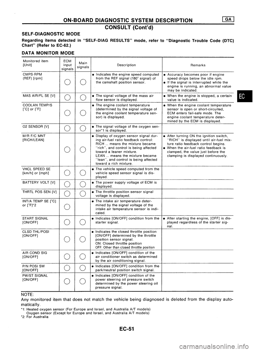
ON-BOARDDIAGNOSTIC SYSTEMDESCRIPTION
CONSULT (ConI'd)
SELF-DIAGNOSTIC MODE
Regarding itemsdetected in"SELF-DIAG RESULTS"mode,referto"Diagnostic TroubleCode(DTC)
Chart" (RefertoEC-62.)
DATA MONITOR MODE
Monitored item ECM
Main
[Unit] input
signals Description
Remarks
signals
CMPS.RPM •Indicates theengine speedcomputed •Accuracy becomespoorifengine
(REF) [rpm]
00
from
theREF signal (180'signal) of
speeddropsbelow theidle rpm.
the camshaft positionsensor.
•Ifthe signal isinterrupted whilethe
engine isrunning, anabnormal value
may beindicated .
MAS AIR/FL SE[V]
0 0
•
The signal voltage ofthe mass air
•When theengine isstopped, acertain
flow sensor isdisplayed .
valueisindicated.
COOLAN TEMP/S
•The engine coolant temperature •When theengine coolant temperature
['C] or['F]
00
(determined
bythe signal voltage of
sensorisopen orshort-circuited,
the engine coolant temperature sen-ECMenters fail-safe mode.The
sor) isdisplayed.
enginecoolant temperature deter-
mined bythe ECM isdisplayed .
02 SENSOR [V]
00
•
The signal voltage ofthe oxygen sen-
sor*1 isdisplayed .
M/R F/CMNT •
Display ofoxygen sensorsignaldur-
•After turning ONthe ignition switch,
[RICH/LEAN] ingair-fuel ratiofeedback control: "RICH"isdisplayed untilair-fuel mix-
RICH ...means themixture became
tureratio feedback controlbegins.
0 0
"rich",
andcontrol isbeing affected •When theair-fuel ratiofeedback is
toward aleaner mixture.
clamped,thevalue justbefore the
LEAN ...means themixture became clampingisdisplayed continuously.
"lean", andcontrol isbeing affected
toward arich mixture .
VHCL SPEED SE
00
•
The vehicle speedcomputed fromthe
[km/h] or[mph] vehicle
speedsensor signalisdis-
played .
BATTERY VOLT[V]
0 0
•
The power supply voltage ofECM is
displayed .
THRTL POSSEN[V]
0 0
•
The throttle position sensorsignal
voltage isdisplayed.
INT/A TEMP SE['C] •The intake airtemperature deter-
or ['F]*2
0
mined
bythe signal voltage ofthe
intake airtemperature sensorisindi-
cated .
START SIGNAL
00
•
Indicates [ON/OFF] conditionfromthe•After starting theengine, [OFF]isdis-
[ON/OFF] startersignal. playedregardless ofthe starter sig-
nal.
CLSD THLIPOSI •Indicates theclosed throttle position
[ON/OFF]
00
[ON/OFF]
determined bythe throttle
position sensorsignal.
ON: Closed throttle position
OFF: Other thanclosed throttle position
AIR COND SIG
00
•
Indicates [ON/OFF] conditionofthe
[ON/OFF] air
conditioner switchasdetermined
by the airconditioning signal.
PIN POSI SW
00
•
Indicates [ON/OFF] conditionfromthe
[ON/OFF] park/neutralpositionswitchsignal.
PW/ST SIGNAL •
Indicates [ON/OFF] conditionofthe
[ON/OFF]
00
power
steering oilpressure switch
determined bythe power steering oil
pressure signal.
NOTE:
Any monitored itemthatdoes notmatch thevehicle beingdiagnosed isdeleted fromthedisplay auto-
matically.
*1: Heated oxygen sensor(ForEurope andIsrael, andAustralia A/Tmodels)
Oxygen sensor(Except forEurope andIsrael, andAustralia A/Tmodels)
*2: For Australia
EC-51
•
Page 773 of 1701
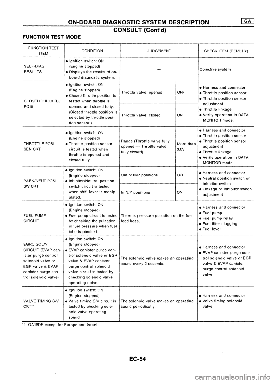
ON-BOARDDIAGNOSTIC SYSTEMDESCRIPTION
CONSULT (Cont'd)
FUNCTION TESTMODE
FUNCTION TEST
CONDITION
ITEM JUDGEMENT
CHECKITEM(REMEDY)
• Ignition switch:ON
SELF-DIAG (Enginestopped)
RESULTS
-
Objective
system
• Displays theresults ofon-
board diagnostic system.
• Ignition switch:ON
•Harness andconnector
(Engine stopped)
Throttlevalve:opened OFF
•Throllle position sensor
• Closed throllle position is
•Throllie position sensor
CLOSED THROTTLE
testedwhenthrottle is
POSI openedandclosed fully. adjustment
(Closed throllieposition is •
Throttle linkage
selected bythrottle posi- Throttle
valve:closed
ON•
Verify operation inDATA
tion sensor.) MONITOR
mode.
• Ignition switch:ON •
Harness andconnector
(Engine stopped) •
Throttle position sensor
THROTTLE POSI•Throllle position sensor Range
(Throllle valvefully
Morethan •
Throllle position sensor
SEN CKT
circuitistested when opened
-Throllle valve
3.DV adjustment
throllie isopened and fully
closed) •Throllie linkage
closed fully. •
Verify operation inDATA
MONITOR mode.
• Ignition switch:ON
•Harness andconnector
(Engine stopoed) Out
ofNIP positions OFF
PARK/NEUT POSI
•Inhibitor/NelJlral position •
Neutral position switchor
SW CKT switchcircuit istested inhibitor
switch
when shiftlever ismanip-
InNIP positions ON•
Linkage orinhibitor switch
ulated . adjustment
• Ignition switch:ON
•Harness andconnector
(Engine stopped)
•Fuel pump
FUEL PUMP •Fuel pump circuit istested
Thereispressure pulsation onthe fuel
•Fuel pump relay
CIRCUIT bychecking thepulsation feedhose.
in fuel pressure whenfuel •
Fuel filter clogging
tube ispinched . •
Fuel level
• Ignition switch:ON
EGRC SOllV (Engine
stopped)
•Harness andconnector
CIRCUIT (EVAPcan-•EVAP canister purgecon-
•EVAP canister purgecon-
ister purge control trolsolenoid valveorEGR
Thesolenoid valvemakes anoperating trolsolenoid valveorEGR
solenoid valveor
valve
&
EVAP canister
soundevery3seconds. valve
&
EVAP canister
EGR valve
&
EVAP purgecontrol solenoid
purgecontrol solenoid
canister purgecon- valvecircuit istested by
valve
trol solenoid valve) checkingsolenoidvalve
operating noise.
• Ignition switch:ON
(Engine stopped) •
Harness andconnector
VALVE TIMING SIV•Valve timing SIVcircuit isThe
solenoid valvemakes anoperating •
Valve timing solenoid
CKT*1 testedbychecking sole-soundperiodically. valve
noid valve operating
sound
'1: GA16DE exceptforEurope andIsrael
EC-54