1995 NISSAN ALMERA N15 Throttle
[x] Cancel search: ThrottlePage 849 of 1701
TROUBLEDIAGNOSIS FORNON-DETECTABLE ITEMS
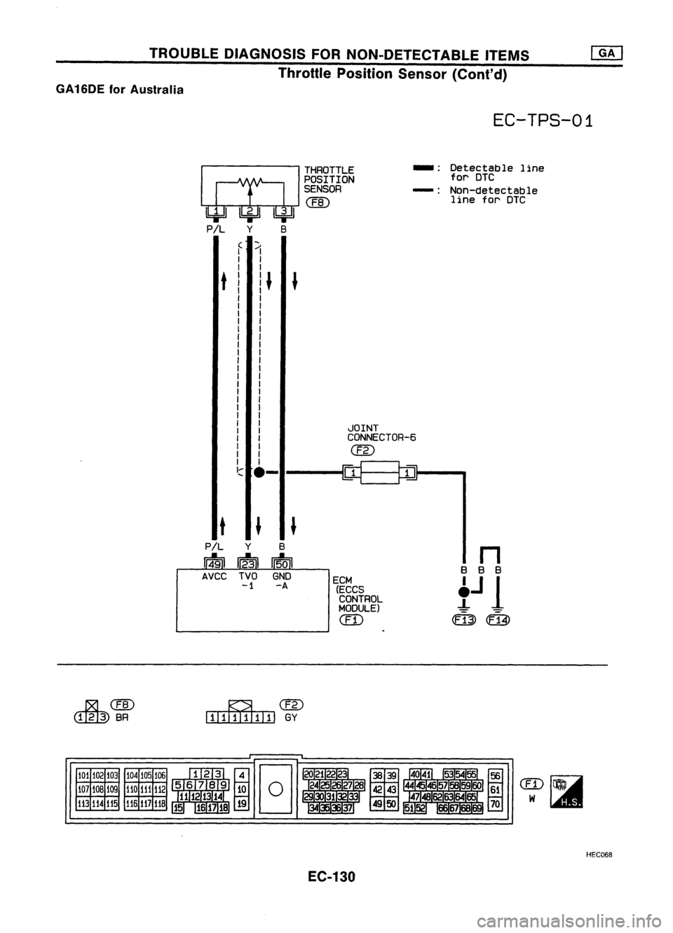
Throttle Position Sensor(Cont'd)
GA16DE forAustralia
~CEID
~BR
EC-TPS-01
THROTTLE
_.
Detectable line
POSITION for
DTC
SENSOR
-:
Non-detectable
CEID
line
forDTC
f "1
I
I
I
I
t
I
q
J
I
I I
I I
I
I
I
I
I
I
I
I
I
I
I
I
I
I
I
I
I
JOINT
I
I
CONNECTOR-6
I
em
I
J
rq
~
I~
.-
t
J
J
P/L
y
B
n
1:91
1:31
15.0
I
BBB
AVCC TVOGND
ECM
!J
1
-1
-A
(ECCS
CONTROL
MODULE)
em
(fi3)
(Fi4)
~cw
EIITIIIIIIIIJ
GY
101 102
103
107 lOB 109
113
114 115 104
105
106
110 111
112
116
117
11B
EC-130 HEC068
Page 850 of 1701
•
INSPECTION
START
m
1
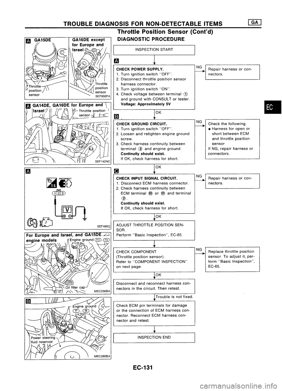
CHECK POWER SUPPLY.
NG
Repair harness orcon-
------.
1. Turn ignition switch"OFF". nectors.
2. Disconnect throttleposition sensor
harness connector.
3. Turn ignition switch"ON".
4. Check voltage between terminal
CD
and ground withCONSULTor tester.
Voltage: Approximately SV
m
1
0K
CHECK GROUND CIRCUIT.
NG
Check thefollowing.
1. Turn ignition switch"OFF".
------.
•Harness foropen or
2. Loosen andretighten engineground short
between ECM
screw. and
throttle position
3. Check harness continuity between sensor
terminal
@
and engine ground. If
NG, repair harness or
Continuity shouldexist.
connectors.
If OK, check harness forshort.
[!J
1
0K
CHECK INPUTSIGNAL CIRCUIT.
NG
Repair harness orcon-
1. Disconnect ECMharness connector.
------.
nectors.
2. Check harness continuity between
ECM terminal
@)
or
@
and terminal
@.
Continuity shouldexist.
If OK, check harness forshort.
~OK
ADJUST THROTTLE POSITIONSEN-
SOR. Perform "BasicInspection", EC-65.
~
CHECK COMPONENT NG
Replace throttleposition
(Throttle positionsensor).
------.
sensor. Toadjust it,per-
Refer to"COMPONENT INSPECTION" form
"Basic Inspection",
on next page. EC-65.
~OK
Disconnect andreconnect harnesscon-
nectors inthe circuit. Thenretest.
~ Trouble isnot fixed.
Check ECMpinterminals fordamage
or the connection ofECM harness con-
nector. Reconnect ECMharness con-
nector andretest.
i
INSPECTION END
SEF480Q
TROUBLE
DIAGNOSIS FORNON-DETECTABLE ITEMS
Throttle Position Sensor(Cont'd)
DIAGNOSTIC PROCEDURE
,~\ C/
Power steering)\
~
m
GA15DE
EC-131
Page 851 of 1701
TROUBLEDIAGNOSIS FORNON-DETECTABLE ITEMS
Throttle Position Sensor(Cont'd)
~io
~ SEF461Q
II
~i8
ECM
E
CONNECTOR
II
20 23
@:
ForAustralia
@:
Except forAustralia
SEF229R
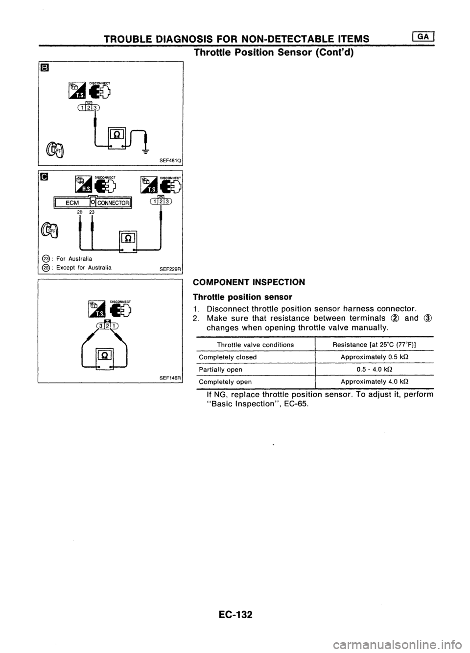
COMPONENT INSPECTION
Throttle position sensor
1. Disconnect throttleposition sensorharness connector.
2. Make surethatresistance betweenterminals
@
and
@
changes whenopening throttlevalvemanually.
SEF146R
Throttle
valveconditions
Completely closed
Partially open
Completely open Resistance
(at25'C (77'F)J
Approximately 0.5
kn
0.5 -4.0
kn
Approximately 4.0
kn
If NG, replace throttleposition sensor.Toadjust it,perform
"Basic Inspection", EC-65.
EC-132
Page 859 of 1701
TROUBLEDIAGNOSIS FORNON-DETECTABLE ITEMS
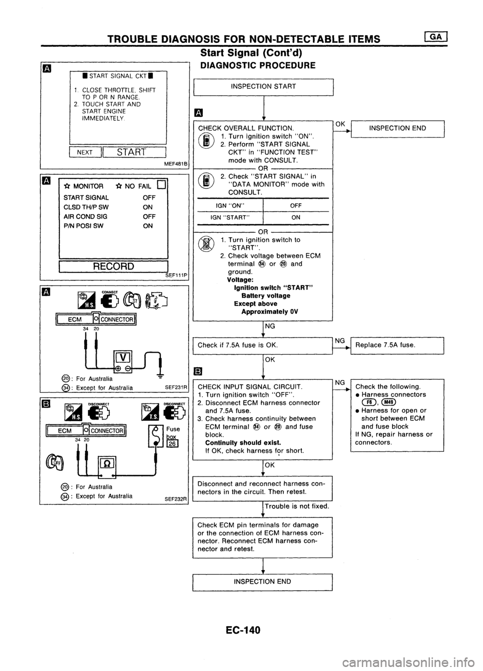
Start Signal (Cont'd)
DIAGNOSTIC PROCEDURE
CHECK OVERALL FUNCTION.
00
1.
Turn ignition switch"ON".
I
II
2.
Perform "STARTSIGNAL
NEXT
START
CKT"
in"FUNCTION TEST"
MEF481B mode
withCONSULT.
OR
m
00
2.
Check "START SIGNAL" in
* MONITOR *
NO FAIL
0
"DATA
MONITOR" modewith
START SIGNAL CONSULT.
OFF
I
CLSDTH/PSW
ONIGN
"ON" OFF
AIR COND SIG OFF
IGN"START" ON
PIN POSI SW ON
II
•
START SIGNAL CKT.
CLOSE THROTTLE. SHIFT
TO POR NRANGE.
2. TOUCH STARTAND
START ENGINE
IMMEDIATELY.
~ __ RE_C_O_R_D_---,l
SEF111P
~I)~ID
ECM
B
CONNECTOR
II
34 20
INSPECTION
START
OR
1. Turn ignition switchto
"START".
2. Check voltage between ECM
terminal @or
@l
and
ground.
Voltage:
Ignition switch"START"
Battery voltage
Except above
Approximately OV
NG OK
INSPECTION END
II
@:
ForAustralia
34 :Except forAustralia
~Io
ECM
ET
CONNECTOR
II
34 20
@:
ForAustralia
@:
Except forAustralia SEF231R
SEF232R Check
if7.5A fuseisOK.
OK
CHECK INPUTSIGNAL CIRCUIT.
1. Turn ignition switch"OFF".
2. Disconnect ECMharness connector
and 7.5A fuse.
3. Check harness continuity between
ECM terminal @or
@l
and fuse
block.
Continuity shouldexist.
If OK, check harness f<;>rshort.
OK
Disconnect andreconnect harnesscon-
nectors inthe circuit. Thenretest.
Trouble isnot fixed.
Check ECMpinterminals fordamage
or the connection ofECM harness con-
nector. Reconnect ECMharness con-
nector andretest.
INSPECTION END
EC-140
NG
NG
Replace
7.5Afuse.
Check thefollowing.
• Harness connectors
(ID,@
• Harness foropen or
short between ECM
and fuse block
If NG, repair harness or
connectors.
Page 869 of 1701
TROUBLEDIAGNOSIS FORNON-DETECTABLE ITEMS
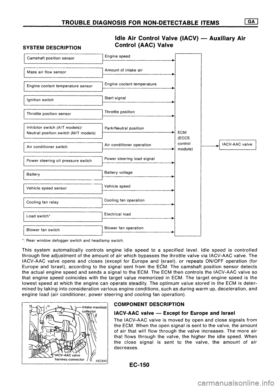
SYSTEM DESCRIPTION Idle
AirControl Valve(IACV) -Auxiliary Air
Control (AAC)Valve
Camshaft positionsensor Engine
speed
I
Mass
airflow sensor Amount
ofintake air
I
Engine coolant temperature sensor Engine
coolant temperature
~
I
Ignition switch Start
signal
I
Throttle positionsensor Throttle
position
~
I
Inhibitor switch(A/Tmodels)/
Park/Neutralposition
Neutral position switch(M/Tmodels) ECM
(ECCS
Air conditioner operation control
!
IACV-AAC valve
I
Air conditioner switch
module)
Power steering oilpressure switch Power
steering loadsignal
I
Battery
~
Battery voltage
Vehicle speedsensor Vehicle
speed
Cooling fanrelay Cooling
fanoperation
Load switch' Electrical
load
Blower fanswitch Blower
fanoperation
': Rear window defogger switchandheadlamp switch.
This system automatically controlsengineidlespeed toaspecified level.Idlespeed iscontrolled
through fineadjustment ofthe amount ofair which bypasses thethrottle valveviaIACV-AAC valve.The
IACV-AAC valveopens andcloses (except forEurope andIsrael), orrepeats ON/OFF operation (for
Europe andIsrael), according tothe signal sentfrom theECM. Thecamshaft positionsensordetects
the actual engine speedandsends asignal tothe ECM. TheECM thencontrols theIACV-AAC valveso
that engine speedcoincides withthetarget valuememorized inECM. Thetarget engine speedisthe
lowest speedatwhich theengine canoperate steadily. Theoptimum valuestored inthe ECM isdeter-
mined bytaking intoconsideration variousengineconditions, suchasduring warmup,deceleration, and
engine load(airconditioner, powersteering andcooling fanoperation).
COMPONENT DESCRIPTION
IACV-AAC valve-Except forEurope andIsrael
The IACV-AAC valveismoved byopen andclose signals from
the ECM. When theopen signal issent tothe valve, theamount
of air that willflow through thevalve increases. Themore air
that flows through thevalve, thehigher theidle speed. When
the close signal issent tothe valve. theamount ofair
decreases.
EC-150
Page 873 of 1701
Repairharness orcon-
nectors. INSPECTION
END
Check thefollowing.
• Harness connectors
QD,@orQD,
@
• 10A fuse
• Harness foropen or
short between IACV-AAC
valve andfuse
If NG, repair harness or
connectors.
NG OK
NG
OK
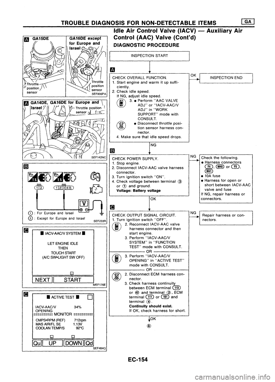
INSPECTION
START
CHECK OVERALL FUNCTION.
1. Start engine andwarm itup suffi-
ciently.
2. Check idlespeed.
If NG, adjust idlespeed.
~ 3.• Perform "AACVALVE
~ ADJ"or"IACV-AACIV
ADJ" in"WORK
SUPPORT" modewith
CONSULT.
• Disconnect throttleposi-
tion sensor harness con-
nector.
4. Make surethatidlespeed drops.
OK
@
CHECK
POWER SUPPLY.
1. Stop engine.
2. Disconnect IACV-AACvalveharness
connector.
3. Turn ignition switch"ON".
4. Check voltage between terminal
@
or
G)
and ground.
Voltage: Batteryvoltage
CHECK OUTPUT SIGNALCIRCUIT.
1. Turn ignition switch"OFF".
(ij\
2.Reconnect IACV-AACvalve
~ harnessconnector andthen
start engine.
3. Perform "IACV-AACIV
SYSTEM" in"FUNCTION
TEST" modewithCONSULT.
OR
(F.I\
3.Perform "IACV-AACIV
~ OPENING" in"ACTIVE TEST"
mode withCONSULT.
OR
M
2.Disconnect ECMharness con-
~ nectar.
3. Check harness continuity
between ECMterminal
(ill)
or
@
and terminal
@,
ECM
terminal
GID
or
@
and
terminal
@.
Continuity shouldexist.
If
OK, check harness forshort.
SEF233R
SEF142NC
o
•
ACTIVE TEST.
LET
ENGINE IDLE
THEN
TOUCH START
(AiC
SW-UGHT SWOFF)
•
IACV-AACN SYSTEM.
I ACV-AACN 34%
OPENING
==========
MONITOR
==========
CMPS-RPM (REF)712rpm
MAS AIRIFL SE 1.13V
COOLAN TEMPtS 92°C
TROUBLE
DIAGNOSIS FORNON-DETECTABLE ITEMS
ffiJ
Idle AirControl Valve(IACV) -Auxiliary Air
Control (AAC)Valve(Cont'd)
DIAGNOSTIC PROCEDURE
!:::=====mul===
I
NEXT" START
I
MEF176E
CD
:
For Europe andIsrael
@ :
Except forEurope andIsrael
~
Ii)
~i5~i5
dfu
CillffuID
illU--illU
~[]fl[OOWN][Qill SEF484Q
EC-154
Page 898 of 1701
TROUBLEDIAGNOSIS FORNON-DETECTABLE ITEMS
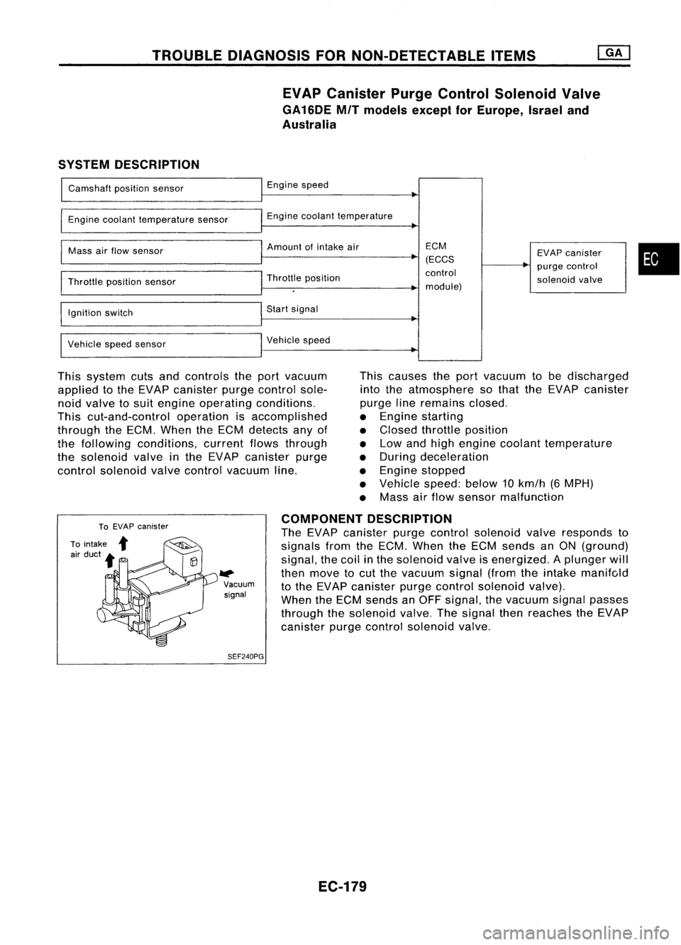
EVAP Canister PurgeControl Solenoid Valve
GA16DE MITmodels exceptforEurope, Israeland
Australia
SYSTEM DESCRIPTION
Camshaft positionsensor
Engine coolant temperature sensor
Mass airflow sensor
Throttle positionsensor
Ignition switch
Vehicle speedsensor Engine
speed
Engine coolant temperature
Amount ofintake air
Throttle position
Start signal
Vehicle speed ECM
(ECCS
control
module) EVAP
canister
purge control
solenoid valve
•
This system cutsandcontrols theport vacuum
applied tothe EVAP canister purgecontrol sole-
noid valve tosuit engine operating conditions.
This cut-and-control operationisaccomplished
through theECM. When theECM detects anyof
the following conditions, currentflowsthrough
the solenoid valveinthe EVAP canister purge
control solenoid valvecontrol vacuum line. This
causes theport vacuum tobe discharged
into theatmosphere sothat theEVAP canister
purge lineremains closed.
• Engine starting
• Closed throttle position
• Low andhigh engine coolant temperature
• During deceleration
• Engine stopped
• Vehicle speed:below10km/h (6MPH)
• Mass airflow sensor malfunction
W>
Vacuum
signal
SEF240PG COMPONENT
DESCRIPTION
The EVAP canister purgecontrol solenoid valveresponds to
signals fromtheECM. When theECM sends anON (ground)
signal, thecoil inthe solenoid valveisenergized. Aplunger will
then move tocut the vacuum signal(fromtheintake manifc,ld
to the EVAP canister purgecontrol solenoid valve).
When theECM sends anOFF signal, thevacuum signalpasses
through thesolenoid valve.Thesignal thenreaches theEVAP
canister purgecontrol solenoid valve.
EC-179
Page 902 of 1701
TROUBLEDIAGNOSIS FORNON-DETECTABLE ITEMS
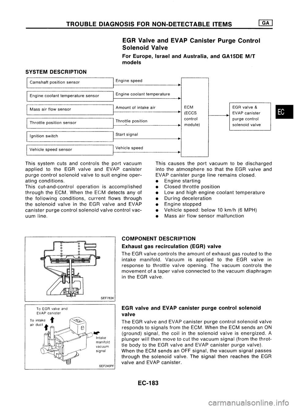
EGR Valve andEVAP Canister PurgeControl
Solenoid Valve
For Europe, IsraelandAustralia, andGA15DE MIT
models
SYSTEM DESCRIPTION
Camshaft positionsensor
Engine coolant temperature sensor
Mass airflow sensor
Throttle position sensor
Ignition switch
Vehicle speedsensor Engine
speed
Engine coolant temperature
Amount ofintake air
Throttle position
Start signal
Vehicle speed ECM
(ECCS
control module) EGR
valve
&
EVAP canister
purge control
solenoid valve
•
This system cutsandcontrols theport vacuum
applied tothe EGR valve andEVAP canister
purge control solenoid valvetosuit engine oper-
ating conditions.
This cut-and-control operationisaccomplished
through theECM. When theECM detects anyof
the following conditions, currentflowsthrough
the solenoid valveinthe EGR valve andEVAP
canister purgecontrol solenoid valvecontrol vac-
uum line. This
causes theport vacuum tobe discharged
into theatmosphere sothat theEGR valve and
EVAP canister purgelineremains closed.
• Engine starting
• Closed throttle position
• Low andhigh engine coolant temperature
• During deceleration
• Engine stopped
• Vehicle speed:below10km/h (6MPH)
• Mass airflow sensor malfunction
SEF783K
l#
Intake
manifold
vacuum signal
SEF240PF COMPONENT
DESCRIPTION
Exhaust gasrecirculation (EGR)valve
The EGR valve controls theamount ofexhaust gasrouted tothe
intake manifold. Vacuumisapplied tothe EGR valve in
response tothrottle valveopening. Thevacuum controls the
movement ofataper valve connected tothe vacuum diaphragm
in the EGR valve.
EGR valve andEVAP canister purgecontrol solenoid
valve
The EGR valve andEVAP canister purgecontrol solenoid valve
responds tosignals fromtheECM. When theECM sends anON
(ground) signal,thecoil inthe solenoid valveisenergized. A
plunger willthen move tocut the vacuum signal(fromthethrot-
tle body tothe EGR valve andEVAP canister purgevalve).
When theECM sends anOFF signal, thevacuum signalpasses
through thesolenoid valve.Thesignal thenreaches theEGR
valve andEVAP canister.
EC-183