1995 NISSAN ALMERA N15 Throttle
[x] Cancel search: ThrottlePage 979 of 1701
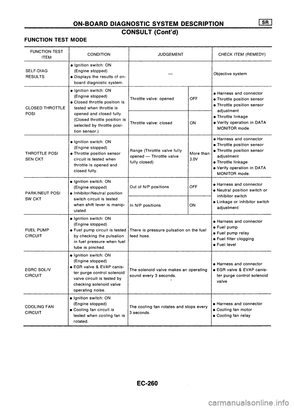
ON-BOARDDIAGNOSTIC SYSTEMDESCRIPTION
CONSULT (Conl'd)
FUNCTION TESTMODE
FUNCTION TEST
CONDITION JUDGEMENTCHECKITEM(REMEDY)
ITEM
•Ignition switch:ON
SELF-DIAG (Enginestopped)
Objectivesystem
-
RESULTS •Displays theresults ofon-
board diagnostic system.
• Ignition switch:ON
•Harness andconnector
(Engine stopped)
Throttlevalve:opened OFF
•Throttle position sensor
• Closed throttle position is
•Throttle position sensor
CLOSED THROTTLE testedwhenthrottle is
POSI opened
andclosed fully. adjustment
• Throttle linkage
(Closed throttleposition is
Throttle valve:closed
ON•
Verify operation inDATA
selected bythrottle posi-
MONITORmode.
tion sensor.)
• Ignition switch:ON •
Harness andconnector
• Throttle position sensor
(Engine stopped)
Range(Throttle valvefully •Throttle position sensor
THROTTLE POSI•Throttle position sensor
opened-Throttle valve More
than
adjustment
SEN CKT circuitistested when 3.QV
throttle isopened and fully
closed) •Throttle linkage
• Verify operation inDATA
closed fully.
MONITORmode.
• Ignition switch:ON
•Harness andconnector
(Engine stopped) Out
ofN/P positions OFF
PARK/NEUT POSI•Inhibitor/Neutral position •
Neutral position switchor
SW CKT switch
circuit istested inhibitor
switch
when shiftlever ismanip-
InN/P positions ON•
Linkage orinhibitor switch
ulated . adjustment
• Ignition. switch:ON
•Harness andconnector
(Engine stopped)
•Fuel pump
FUEL PUMP •Fuel pump circuit istested
Thereispressure pulsation onthe fuel
•Fuel pump relay
CIRCUIT bychecking thepulsation feedhose.
in fuel pressure whenfuel •
Fuel filter clogging
tube ispinched . •
Fuel level
• Ignition switch:ON
(Engine stopped)
•Harness andconnector
EGRC SOLIV •
EGR valve
&
EVAP canis-
Thesolenoid valvemakes anoperating •
EGR valve
&
EVAP canis-
CIRCUIT ter
purge control solenoid
soundevery3seconds. terpurge control solenoid
valve circuit istested by
.
valve
checking solenoidvalve
operating noise.
• Ignition switch:ON
COOLING FAN (Engine
stopped)
Thecooling fanrotates andstops every •
Harness andconnector
• Cooling fancircuit is •Cooling fanmotor
CIRCUIT testedwhencoaling fanis3
seconds.
•Cooling fanrelay
rotated.
EC-260
Page 986 of 1701
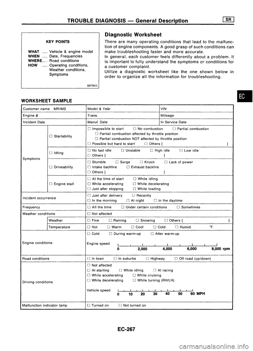
TROUBLEDIAGNOSIS -General Description
KEY POINTS
WHAT .....
Vehicle &engine model
WHEN
Date,Frequencies
WHERE Roadconditions
HOW Operatingconditions,
Weather conditions,
Symptoms
SEF907L
WORKSHEET SAMPLE Diagnostic
Worksheet
There aremany operating conditions thatlead tothe malfunc-
tion ofengine components. Agood grasp ofsuch conditions can
make troubleshooting fasterandmore accurate.
In
general, eachcustomer feelsdifferently aboutaproblem. It
is important tofully understand thesymptoms orconditions for
a customer complaint.
Utilize adiagnostic worksheet liketheone shown belowin
order toorganize allthe information fortroubleshooting.
•
Customer name
MR/MS Model
&
Year VIN
Engine
#
Trans. Mileage
Incident Date Manuf.Date InService Date
o
Impossible tostart
o
No combustion
o
Partial combustion
o
Startability
o
Partial combustion affectedbythrottle position
o
Partial combustion NOTaffected bythrottle position
o
Possible buthard tostart
o
Others [
]
o
No fast idle
o
Unstable
o
High idle
o
Low idle
[J
Idling
o
Others [
]
Symptoms
[J
Stumble
o
Surge
o
Knock
o
Lack ofpower
o
Driveability
o
Intake backfire
o
Exhaust backfire
o
Others [
]
o
At the time ofstart
o
While idling
o
Engine stall
o
While accelerating
o
While decelerating
o
Just after stopping
o
While loading
Incident occurrence
o
Just after delivery
o
Recently
o
Inthe morning
o
At night
o
Inthe daytime
Frequency
o
All the time
o
Under certain conditions
o
Sometimes
Weather conditions
o
Not affected
Weather
o
Fine DRaining
o
Snowing
o
Others [
]
Temperature
o
Hot
o
Warm
o
Cool
o
Cold
o
Humid
of
o
Cold
o
During warm-up
o
After warm-up
Engine conditions
Enginespeed
I
I
I
I
I
I
I
I
I
0 2,000 4,000
6,000 8,000rpm
Road conditions
o
Intown
o
Insuburbs
o
Highway
o
Off road (up/down)
o
Not affected
o
At starting
o
While idling
o
At racing
o
While accelerating
o
While cruising
Driving conditions
o
While decelerating
o
While turning (RH/LH)
Vehicle speed
I
I
I
I
I
I
II
I
I
I
II
0 10 20 3040
5060
MPH
Malfunction indicatorlamp
o
Turned on
o
Not turned on
EC-267
Page 987 of 1701
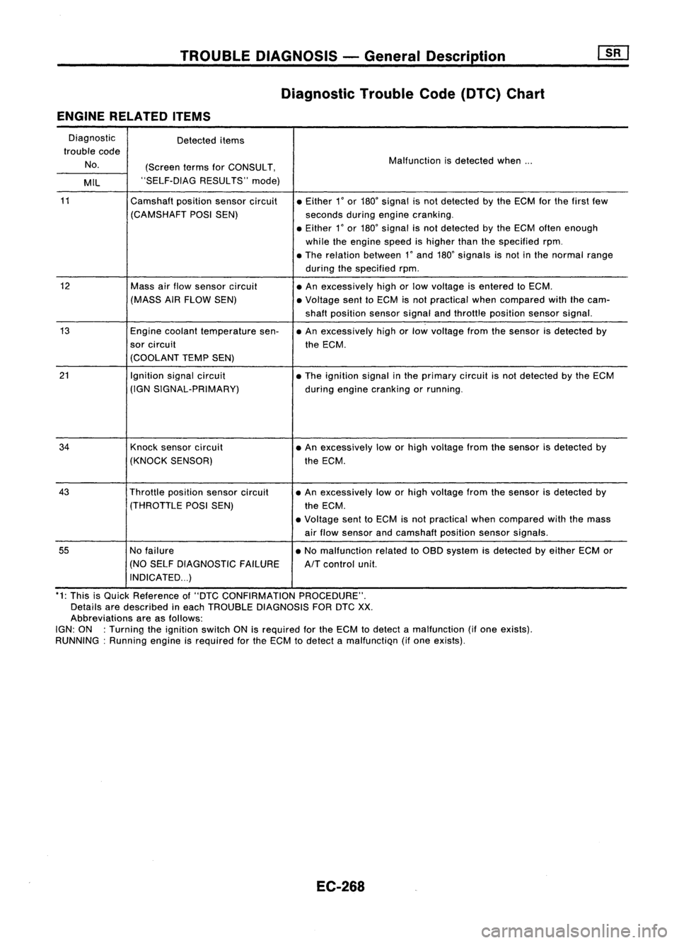
TROUBLEDIAGNOSIS -General Description
Diagnostic TroubleCode(DTC) Chart
ENGINE RELATED ITEMS
Diagnostic Detecteditems
trouble code
No. (ScreentermsforCONSULT, Malfunction
isdetected when...
MIL "SELF-DIAG
RESULTS"mode)
11
Camshaftpositionsensorcircuit •Either
1
0
or
180
0
signal isnot detected bythe ECM forthe first few
(CAMSHAFT POSISEN) secondsduringengine cranking .
• Either
1
0
or
180
0
signal isnot detected bythe ECM often enough
while theengine speedishigher thanthespecified rpm.
• The relation between
1"
and
180"
signals isnot inthe normal range
during thespecified rpm.
12
Massairflow sensor circuit
•An excessively highorlow voltage isentered toECM.
(MASS AIRFLOW SEN) •Voltage senttoECM isnot practical whencompared withthecam-
shaft position sensorsignalandthrottle position sensorsignal.
13
Enginecoolant temperature sen-•An excessively highorlow voltage fromthesensor isdetected by
sor circuit theECM.
(COOLANT TEMPSEN)
21
Ignitionsignalcircuit
•The ignition signalinthe primary circuitisnot detected bythe ECM
(IGN SIGNAL-PRIMARY)
duringengine cranking orrunning.
34
Knocksensor circuit •An excessively loworhigh voltage fromthesensor isdetected by
(KNOCK SENSOR) theECM .
43
Throttlepositionsensorcircuit •
An excessively loworhigh voltage fromthesensor isdetected by
(THROTTLE POSISEN)
theECM.
• Voltage senttoECM isnot practical whencompared withthemass
air flow sensor andcamshaft positionsensorsignals.
55
Nofailure •No malfunction relatedtoOBD system isdetected byeither ECMor
(NO SELF DIAGNOSTIC FAILURE
AIT
control unit.
INDICATED ...)
*1: This isQuick Reference of"DTC CONFIRMATION PROCEDURE".
Details aredescribed ineach TROUBLE DIAGNOSIS FORDTC
XX.
Abbreviations areasfollows:
IGN: ON :Turning theignition switchONisrequired forthe ECM todetect amalfunction (ifone exists).
RUNNING: Runningengineisrequired forthe ECM todetect amalfunctiQn (ifone eXists).
EC-268
Page 988 of 1701
![NISSAN ALMERA N15 1995 Service Manual TROUBLEDIAGNOSIS -General Description
ill]
Diagnostic TroubleCode(DTC) Chart(Cont'd)
x:
Applicable
-: Not applicable
"DTC *1
*2
Check Items CONFIRMATION
"OVERALLFUNC-
Fail ReferencePag NISSAN ALMERA N15 1995 Service Manual TROUBLEDIAGNOSIS -General Description
ill]
Diagnostic TroubleCode(DTC) Chart(Cont'd)
x:
Applicable
-: Not applicable
"DTC *1
*2
Check Items CONFIRMATION
"OVERALLFUNC-
Fail ReferencePag](/manual-img/5/57349/w960_57349-987.png)
TROUBLEDIAGNOSIS -General Description
ill]
Diagnostic TroubleCode(DTC) Chart(Cont'd)
x:
Applicable
-: Not applicable
"DTC *1
*2
Check Items CONFIRMATION
"OVERALLFUNC-
Fail ReferencePage
(Possible Cause) PROCEDURE"
TIONCHECK"
Safe
Quick Ref. QuickRef. System
• Harness orconnectors
(The sensor circuitisopen orshorted.)
• Camshaft positionsensor
RUNNING
--
EC-289
• Starter motor
• Starting systemcircuit(ELsection)
• Dead (Weak) battery
• Harness orconnectors
-
(The sensor circuitisopen orshorted.) RUNNING
RUNNING
X
EC-293
• Mass airflow sensor
• Harness orconnectors
(The sensor circuitisopen orshorted.) IGN:
ON
-
X
EC-297
• Engine coolant temperature sensor
• Harness orconnectors
(The ignition primary circuitisopen orshorted.)
• Power transistor unit RUNNING
--
EC-301
• Camshaft positionsensor
• Camshaft positionsensorcircuit
• Harness orconnectors
(The sensor circuitisopen orshorted.) RUNNING
--
EC-306
• Knock sensor
• Harness orconnectors
(The sensor circuitisopen orshorted.)
-
IGN:
ON
X
EC-309
• Throttle position sensor
• No failure
--
-
-
*2: •The "OVERALL FUNCTIONCHECK"isasimplified andeffective waytoinspect acomponent orcircuit.
In some cases, the"OVERALL FUNCTIONCHECK"isused rather thana"DIAGNOSTIC TROUBLECODECONFIRMA-
TION PROCEDURE".
When noDTC CONFIRMATION PROCEDUREisavailable, the"NG" result ofthe OVERALL FUNCTION CHECKcanbe
considered tomean thesame asaDTC detection .
• During an"NG" OVERALL FUNCTION CHECK,theDTC might notbeconfirmed.
EC-269
•
Page 989 of 1701
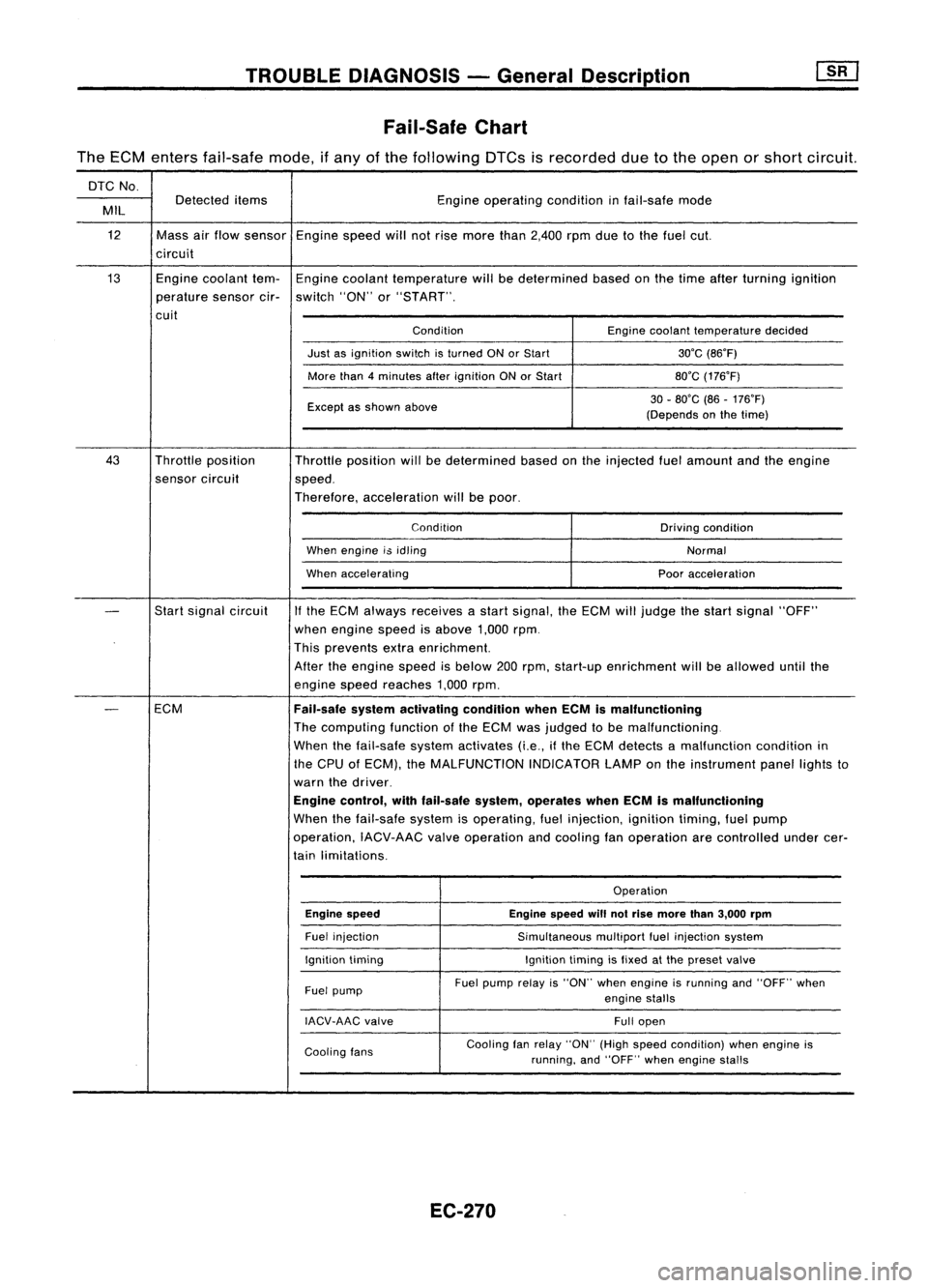
TROUBLEDIAGNOSIS -General Description
Fail-Safe Chart
The ECM enters fail-safe mode,ifany ofthe following DTCsisrecorded duetothe open orshort circuit.
DTC No.
Detected items Engineoperating conditioninfail-safe mode
MIL
12 Massairflow sensor Enginespeedwillnotrise more than2,400 rpmduetothe fuel cut.
circuit
13 Enginecoolant tem-Engine coolant temperature willbedetermined basedonthe time after turning ignition
perature sensorcir-switch "ON"or"START".
cuit ConditionEnginecoolant temperature decided
Just asignition switchisturned ONorStart 30'C(86'F)
More than4minutes afterignition ONorStart 80'C(176'F)
Except asshown above 30
-80'C (86-176'F)
(Depends onthe time)
43 Throttle position
Throttleposition willbedetermined basedonthe injected fuelamount andtheengine
sensor circuit
speed.
Therefore, acceleration willbepoor.
Condition Drivingcondition
When engine i$idling
Normal
When accelerating Pooracceleration
-
Start
signal circuit
If
the ECM always receives astart signal, theECM willjudge thestart signal "OFF"
when engine speedisabove 1,000rpm.
This prevents extraenrichment.
After theengine speedisbelow 200rpm, start-up enrichment willbeallowed untilthe
engine speedreaches 1,000rpm.
-
ECM
Fail-safesystemactivating conditionwhenECMismalfunctioning
The computing functionofthe ECM wasjudged tobe malfunctioning.
When thefail-safe systemactivates (i.e.,ifthe ECM detects amalfunction conditionin
the CPU ofECM), theMALFUNCTION INDICATORLAMPonthe instrument panellightsto
warn thedriver.
Engine control, withfail-safe system,operates whenECMismalfunctioning
When thefail-safe systemisoperating, fuelinjection, ignitiontiming,fuelpump
operation, IACV-AACvalveoperation andcooling fanoperation arecontrolled undercer-
tain limitations.
Operation
Engine speed Enginespeedwillnotrise more than3,000 rpm
Fuel injection
Simultaneousmultiportfuelinjection system
Ignition timing Ignitiontimingisfixed atthe preset valve
Fuel pump Fuel
pump relayis"ON" whenengine isrunning and"OFF" when
engine stalls
IACV-AAC valve
Fullopen
Cooling fans Cooling
fanrelay "ON" (Highspeed condition) whenengine is
running, and"OFF" whenengine stalls
EC-270
Page 990 of 1701
TROUBLEDIAGNOSIS -General Descrip_ti_on
1S_R_'
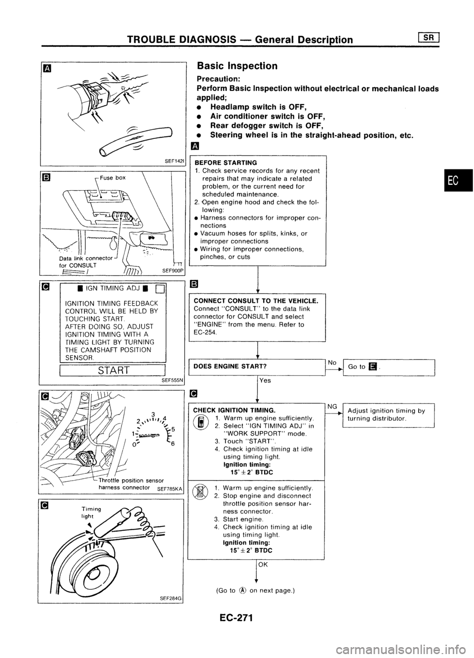
Basic Inspection
Precaution:
Perform BasicInspection withoutelectrical ormechanical loads
applied;
• Headlamp switchisOFF,
• Air conditioner switchisOFF,
• Rear defogger switchisOFF,
• Steering wheelisinthe straight-ahead position,etc.
m
BEFORE STARTING
1. Check service records forany recent •
repairs thatmay indicate arelated
problem, orthe current needfor
scheduled maintenance.
2. Open engine hoodandcheck thefol-
lowing:
• Harness connectors forimproper con-
nections
• Vacuum hosesforsplits, kinks,or
improper connections
• Wiring forimproper connections,
pinches, orcuts
Goto
(I.
No
CONNECT
CONSULTTOTHE VEHICLE.
Connect "CONSULT" tothe data link
connector forCONSULT andselect
"ENGINE" fromthemenu. Referto
EC-254.
DOES ENGINE START?
\\
~
~ SEF1421
START
•
IGN TIMING ADJ.
0
IGNITION TIMINGFEEDBACK
CONTROL WILLBEHELD BY
TOUCHING START
AFTER DOING SO,ADJUST
IGNITION TIMINGWITHA
TIMING LIGHTBYTURNING
THE CAMSHAFT POSITION
SENSOR.
SEF555N
Yes
CHECK IGNITION TIMING.
(ij\
1.Warm upengine sufficiently.
~ 2.Select "IGNTIMING ADJ"in
"WORK SUPPORT" mode.
3. Touch "START".
4. Check ignition timingatidle
using timing light.
Ignition timing:
15°::f:2° BTDC
~ 1Warm upengine sufficiently.
~ 2:
Stop engine anddisconnect
throttle position sensorhar-
ness connector.
3. Start engine.
4. Check ignition timingatidle
using timing light.
Ignition timing:
15°::f:2° BTDC
OK
(Go to
@
onnext page.) Adjust
ignition timingby
turning distributor.
EC-271
Page 991 of 1701
![NISSAN ALMERA N15 1995 Service Manual
I!]
CHECK IDLEADJ. SCREW INITIALSET
NG
Adjust engine speedby
---..
RPM.
turningidleadjusting
00
1.
Select "IGNTIMING ADJ"in screw.
"WORK SUPPORT" mode.
2. When touching "STAR NISSAN ALMERA N15 1995 Service Manual
I!]
CHECK IDLEADJ. SCREW INITIALSET
NG
Adjust engine speedby
---..
RPM.
turningidleadjusting
00
1.
Select "IGNTIMING ADJ"in screw.
"WORK SUPPORT" mode.
2. When touching "STAR](/manual-img/5/57349/w960_57349-990.png)
I!]
CHECK IDLEADJ. SCREW INITIALSET
NG
Adjust engine speedby
---..
RPM.
turningidleadjusting
00
1.
Select "IGNTIMING ADJ"in screw.
"WORK SUPPORT" mode.
2. When touching "START",
does engine speedfallto
750:!: 50rpm
(AfT
in
"N"
posi-
tion)?
OR
00
Does
engine runat750:!: 50rpm
(AfT
In
"N"
position)?
OK
Reconnect throttleposition sensorhar-
ness connector.
Ii
CHECK THROTTLE POSITIONSENSOR
NG
Adjust outputvoltage to
IDLE POSITION.
---..
0.50Vbyrotating throttle
00
1.
Perform ''THRTLPOSSEN
positionsensorbody.
ADJ" in"WORK SUPPORT"
1
mode.
2. Check thatoutput voltage of
RESETIDLEPOSITION
throttle position sensoris
MEMORY.
approx. 0.35to0.65V (Throttle
1.Warm upengine suffi-
valve fullycloses.) and"CLSD ciently.
2. Turn ignition switch
THLIPOSI" stays"ON".
"OFF"andwait at
OR least5seconds.
00
Measure
outputvoltage ofthrot- 3.
Disconnect throttle
position sensorhar-
tie position sensorusing
nessconnector.
voltmeter, andcheck thatitis
4.
Start engine andwait
approx. 0.35toO.65V. (Throttle at
least 5seconds in
"N" position.
valve fullyclosed.)
5.Reconnect throttle
OK • position
sensorhar-
ness connector while
running engine.
~
1
,
THRTL
POSSEN O,52V
SEF165P
•••
ADJMONITOR •••
TROUBLE
DIAGNOSIS -General Description
Basic Inspection (Cont'd)
@
========
MONITOR
========
CMPS.RPM (REF)Orpm
CLSDTHUP ON
Ii
•
THRTL POSSENADJ
.0
I!]
•IGN TIMING ADJ.
0
IGNITION TIMINGFEEDBACK
CONTROL WILLBEHELD BY
TOUCHING START
AFTER DOING SO,ADJUST
IGNITION TIMINGWITHA
TIMING LIGHTBYTURNING
THE CAMSHAFT POSITION
SENSOR
I
START
I
SEF546N
CID
(Go tonext page)
EC-272
Page 994 of 1701
TROUBLEDIAGNOSIS -General Description
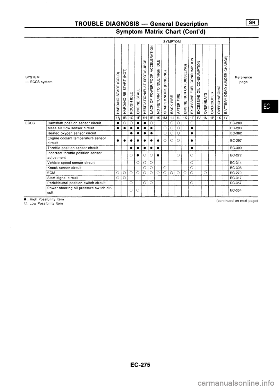
Symptom MatrixChart(Cont'd)
SYMPTOM
z
0
1=
0::
Z
W
w w
CJ
..J
W
0
Z
CJ
W
..J
1=
0
0::
0::
()
9
5
Q.
1=
::::>
()
z
:2
I
i='
en
I
5
::;
Q.
()
is'
0
;:::
CJ
::::>
:2
0::
~
0::
:r:
z
w
en
::::>
SYSTEM
..J
0
0
en
z
w
Reference
0
Q.
W
e;
w
en
0
- ECCS system
~
....
en
0
..J
Z
9-
0
z
Z
0::
Q.
9
a:
()
0
2-
page
....
....
ii:
..J
U
....
Z
CJ
0::
..J
W
0
W
..J
0
en
..J
u-
s:
.... ::.:::
0
::::>
0
z
W
..J
U
u-
e;
....
w
Z
0
z
0
w
z
(/)
en
w
en
0::
..J
....
Q.
W
::::>
w
w
....
..J
0::
0
0 0
9
en
0
0::
Z
0::0::
0::
>>
0
>-
~
u-
::::>::.:::
u:
enen
0
I
Z Z
W
0
....
u:
w
W
0::
2i 2i
I
Z
W
::.:::
0::
z
en
(/)
I
()
()
w
CJ
e;
....
::.:::
0:: 0::
::.:::
w w
W
0::
0::
0::
1=
0::
0::
::::>
en
()
()
....
e;
uu
w
w
w
0
Z
w
0
Q.
u-
Z
x x
> >>
I I
0::
W
I
..J
Z
(/)
1Il
w
w w
000
1Il
11\ 18
1C 1F
1H 1R
1S1M 1J1L1K
1T
1V1N 1P1X
1Y
ECCS Camshaft
positionsensorcircuit
•
0
0
••
0
000 0
EC-289
Mass airflow sensor circuit
•••
•••
0
00
•
EC-293
Heated oxygen sensorcircuit
••
••
0
00
•
EC-362
Engine coolant temperature sensor
••• ••
•
•
0
0
0
•
EC-297
circuit
Throttle positionsensorcircuit
••
••
• •
EC-309
Incorrect fhrottleposition sensor
0
•
0
0
•
0
0
EC-272
adjustment
Vehicle speedsensor circuit
000
0
EC-314
Knock sensor circuit
00
0 0
EC-306
ECM
0
0
0
0
00000
0
00 0
EC-270
Start signal circuit
00
EC-317
Park/Neutral positionswitchcircuit
000
0
EC-357
Power steering oilpressure switchcir-
0
0
EC-354
cuit
•
• ;High Possibility Item
0;
Low Possibility Item
EC-275
(continued
onnext page)