1995 NISSAN ALMERA N15 bulb
[x] Cancel search: bulbPage 325 of 1701

TROUBLEDIAGNOSES
Self-diagnosis (ForEurope) (Cont'd)
MALFUNCTION CODE/SYMPTOM CHART
Code No.
Malfunctioningpart Diagnostic
procedure
(No. ofwarning lampflashes)
45
Actuator
frontleftoutlet solenoid valve
3
46
Actuator
frontleftinlet solenoid valve
3
41
Actuator
frontrightoutlet solenoid valve
3
42
Actuator
frontrightinletsolenoid valve
3
51
Actuator
rearright outlet solenoid valve
3
52
Actuatorrearright inletsolenoid valve
3
55
Actuator
rearleftoutlet solenoid valve
3
56
Actuator
rearleftinlet solenoid valve
3
25
Frontleftsensor (open-circuit)
4
26
Front
leftsensor (short-circuit)
4
21
Frontrightsensor (open-circuit)
4
22
Front
rightsensor (short-circuit)
4
35
Rearleftsensor (open-circuit)
4
36
Rear
leftsensor (short-circuit)
4
31
Rearrightsensor (open-circuit)
4
32
Rearrightsensor (short-circuit)
4
18
Sensorrotor
4
61
Actuatormotorormotor relay
5
63
Solenoidvalverelay
6
57
Powersupply (Lowvoltage)
7
71
Controlunit
8
Control unitpower supply circuit
Warning lampstays onwhen igni-Warning
lampbulbcircuit
tion switch isturned on Control
unitorcontrol unitconnector
2
Solenoid valverelaystuck
Power supply forsolenoid valverelaycoil
Warning lampstays on,during
Controlunit
-
self-diagnosis
Warning lampdoesnotcome onFuse, warning lampbulborwarning lampcircuit
1
when ignition switchisturned onControl unit
Warning lampdoes notcome on
Control unit
during self-diagnosis
-
Pedal vibration andnoise
-
9
Long stopping distance
-
10
Unexpected pedalaction
-
11
ABS does notwork
-
12
ABS works frequently
-
13
BR-55
•
Page 335 of 1701

TROUBLEDIAGNOSES
OK
Max
line
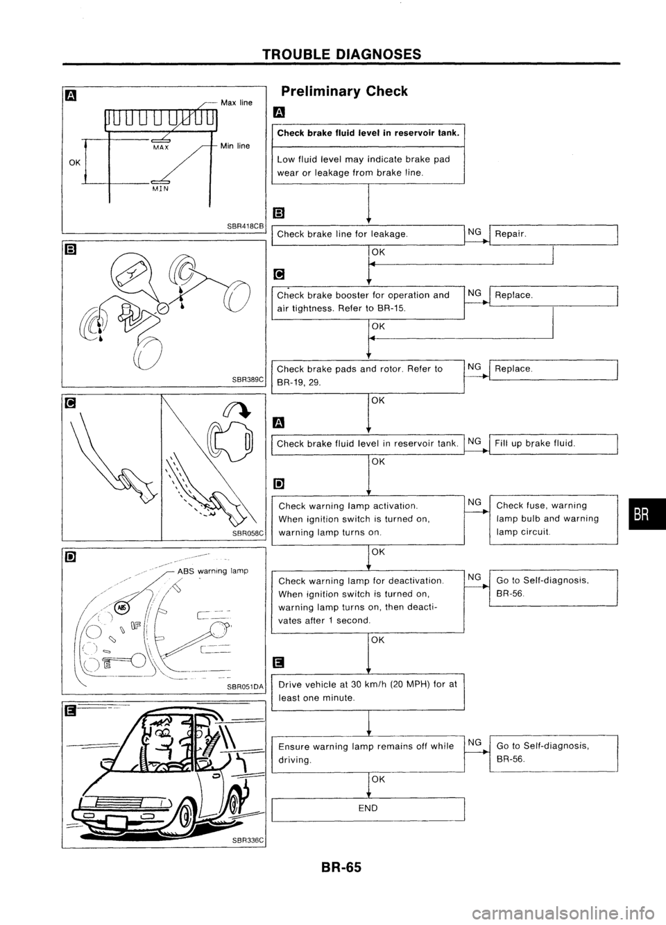
Min line Preliminary
Check
m
Check brakefluidlevel inreservoir tank.
Low fluid level mayindicate brakepad
wear orleakage frombrake line.
SBR418CB
Checkbrakelineforleakage. NG
Repair.
Check brakefluidlevel inreservoir tank.NGFillupbrake fluid.
OK
•
Check
fuse,warning
lamp bulbandwarning
lamp circuit.
Replace.
NG
NG
Replace.
NG
OK
OK OK
t
Check brakebooster foroperation and
air tightness. RefertoBR-15.
Check brakepadsandrotor. Referto
BR-19,29.
Check warning lampactivation.
When ignition switchisturned on,
SBR058C
warninglampturns on.
SBR389C
-~--
iii' -,/"
ASS,:"arnlng lamp
/~
,/~
/ //>Jf,
I
/' " /-..,J
C
~" ,J \)
003
i
,A',.!.,
(')
~---
(-ji=o -[--
~"
-,--
'-,--_ ..
OK
Check warning lampfordeactivation.
When ignition switchisturned on,
warning lampturns on,then deacti.
vates after1second.
OK NG
GotoSelf-diagnosis,
BR-56.
SBR051DA
Drivevehicle at30 km/h (20MPH) forat
least oneminute.
Ensure warning lampremains offwhile
driving.
OK
END
NG
GotoSelf-diagnosis,
BR-56.
BR-65
Page 338 of 1701

TROUBLEDIAGNOSES
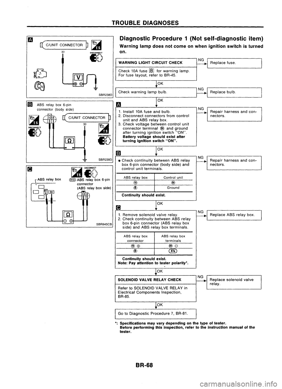
Diagnostic Procedure1(Not self-diagnostic item)
Warning lampdoes notcome onwhen ignition switchisturned
on.
c(
C/UNIT CONNECTOR
30
p~
15
SBR238D WARNING
LIGHTCIRCUIT CHECK
Check 10Afuse ~forwarning lamp.
For fuse layout, refertoSR-4S.
OK
Check warning lampbulb.
NG
NG
Replace
fuse.
Replace bulb.
Ii) ASSrelay box6-pin
connector (bodyside)
~ 108
c(
C/UNIT CONNECTOR
P
I...a1
30~
15
l.41
Iv
OK
1. Install 10Afuse andbulb.
2. Disconnect connectors fromcontrol
unit and ASS relay box.
3. Check voltage between controlunit
connector terminal
@
and ground
after turning ignition switch"ON".
Battery voltage shouldexistafter
turning ignition switch
"ON".
OK
NG
Repair harness andcon-
nectors.
OK
Continuity
shouldexist.
•
Check continuity betweenASSrelay
box 6-pin connector (bodyside)and
control unitterminals.
\ ASS relay box
f~~~_
SBR239D
~i5
@ID
ASS relay box6-pin
connector (ASS relayboxside)
108
ASS
relay box
@)
unit
@
Ground
NG
Repair harness andcon-
nectors.
1. Remove solenoid valverelay.
2. Check continuity betweenASSrelay
SBR945CB
box6-pin connector (ASSrelaybox
side) andASS relay boxterminals.
ASS relay box ASS
relay box
connector terminals
@)\B
@e
Continuity shouldexist.
Note: Payattention totester polarity",
OK
SOLENOID VALVERELAYCHECK
Refer toSOLENOID VALVERELAY in
Electrical Components Inspection,
BR-8S.
OK
Go toDiagnostic Procedure7,BR-81.
NG
NG
Replace
ABSrelay box.
Replace solenoid valve
relay.
": Specifications mayvary depending onthe type oftester.
Before performing thisinspection, refertothe instrucllon manualofthe
tester.
BR-68
Page 373 of 1701

ELECTRICALSYSTEM
SECTION
EL
When youread wiring diagrams:
• Read GIsection, "HOWTOREAD WIRING DIAGRAMS".
When youperform troublediagnos.es, readGIsection, "HOWTOFOllOW FLOWCHART
IN TROUBLE DIAGNOSES" and"HOW TOPERFORM EFFICIENT DIAGNOSIS FORAN
ELECTRICAL INCIDENT".
CONTENTS
PRECAUTIONS 4
Supplemental RestraintSystem(SRS)"AIR
BAG" (DualAirBag System) 4
Supplemental RestraintSystem(SRS)"AIR
BAG" (Single AirBag System) 4
HARNESS CONNECTOR 5
Description 5
STANDARDIZED RELAy 6
Description 6
POWER SUPPLY ROUTING 8
Schematic 8
Wiring Diagram -POWER - 10
Fuse 19
Fusible Link 19
Circuit Breaker 19
GROUND DISTRIBUTION 20
BATTERy 25
How toHandle Battery 25
Battery TestandCharging Chart.. 28
Service DataandSpecifications (SOS) 32
STARTING SySTEM
33
Wiring Diagram -START - 33
Trouble Diagnoses 35
Construction 36
Removal andInstallation .45
Magnetic SwitchCheck .46
Pinion/Clutch Check 46
Brush Check 46
Yoke Check 47
Armature Check 48
Assembly .49
Service DataandSpecifications (SDS) 50
CHARGING SYSTEM 52
Wiring Diagram -CHARGE - 52
Trouble Diagnoses 54Construction
55
Removal andInstallation 57
Disassembly 57
Rotor Check 57
Brush Check 58
Stator Check 58
Diode Check 59
Assembly 60
Service DataandSpecifications (SDS) 61
COMBINATION SWITCH 62
Combination Switch/Check 62
Replacement 64
HEADLAMP -Without Daytime lightSystem -65
Wiring Diagram -H/LAMP - 65
Trouble Diagnoses 67
HEADLAMP -Daytime lightSystem - 68
Operation (Daytimelightsystem) 68
System Description 69
Schematic 70
Wiring Diagram -DTRL - 71
Trouble Diagnoses (DaytimeLight) 74
HEADLAMP 75
Bulb Replacement... 75•
Aiming Adjustment. 75
HEADLAMP -Headlamp Aiming
Control- 77
Wiring Diagram -AIM - 77
Description 81
EXTERIOR LAMP 82
Clearance, LicenseandTail Lamps/Schematic 82
Clearance, LicenseandTail Lamps/Wiring
Diagram -TAILIL - 83
Stop Lamp/Wiring Diagram-STOP/L - 92
Back-up Lamp/Wiring Diagram-BACK/L -94
Front FogLamp/Wiring Diagram-F/FOG -96
Front FogLamp BulbReplacement 101
Page 374 of 1701

CONTENTS(Conl'd.)
Front FogLamp Aiming Adjustment.. 101
Rear FogLamp/Wiring Diagram-R/FOG -102
Turn Signal andHazard Warning Lamps/
Schematic 106
Turn Signal andHazard Warning
Lamps/Wiring Diagram-TURN - 107
Turn Signal andHazard Warning
Lamps/Trouble Diagnoses 113
Combination FlasherUnitCheck 113
Bulb Specifications 114
INTERIOR LAMP 115
Illumination/Schematic 115
Illumination/Wiring Diagram-ILL - 116
Interior, Spot,Trunk Room andLuggage
Room Lamps/Wiring Diagram-INT/L - 122
Bulb Specifications 126
METER ANDGAUGES 127
Combination Meter 127
Speedometer, Tachometer,Temp.andFuel
Gauges/Wiring Diagram-METER - 129
Inspection/Fuel GaugeandWater
Temperature Gauge 133
Inspection/Tachometer 134
Inspection/Speedometer andVehicle Speed
Sensor 135
Fuel Tank Gauge UnitCheck 137
Thermal Transmitter Check 137
Vehicle SpeedSensor SignalCheck 137
WARNING LAMPSANDBUZZER 138
Warning Lamps/Schematic 138
Warning Lamps/Wiring Diagram-WARN -139
Oil Pressure SwitchCheck 151
Fuel Warning LampSensor Check 151
Diode Check 151
Warning BuzzerUnit... 151
Warning Buzzer/System Description 152
Warning Buzzer/Wiring Diagram
- BUZZER - 154
Components Inspection-Warning Buzzer 157
WIPER ANDWASHER 160
Front Wiper andWasher/System Description160
Front Wiper andWasher/Wiring Diagram
- WIPER - 162
Front Wiper Amplifier Check 166
Front Wiper Installation andAdjustment.. 166
Front Wiper Linkage 167
Front Washer NozzleAdjustment... 168
Front Washer TubeLayout 168
Rear Wiper andWasher/System Description169Rear
Wiper andWasher/Wiring Diagram
- WIP/R - 171
Rear Wiper Amplifier Check 175
Rear Wiper Installation andAdjustment.. 175
Rear Washer NozzleAdjustment 175
Rear Washer TubeLayout.. 176
Check Valve(forrear washer) 176
Headlamp WiperandWasher/Wiring Diagram
- HLC - 177
Headlamp WiperMotorCheck 179
Headlamp WiperInstallation 179
Headlamp WasherTubeLayout.. 179
Check Valve(Forheadlamp washer) 179
POWER WINDOW 180
System Description 180
Schematic 183
Wiring Diagram -WINDOW - 185
Trouble Diagnoses 197
POWER DOORLOCK 198
System Description 198
Schematic 200
Wiring Diagram -D/LOCK - 202
Trouble Diagnoses -Type 1(For Europe and
Austral ia) 212
Trouble Diagnoses -Type 2(Except for
Europe andAustralia) 216
POWER DOORMIRROR 220
Wiring Diagram -MIRROR - 220
ELECTRIC SUNROOF 224
Wiring Diagram -SROOF - 224
HORN, CIGARETTE LIGHTERANDCLOCK 226
Wiring Diagram -HORN - 226
REAR WINDOW DEFOGGER ANDDOOR
MIRROR DEFOGGER 230
System Description (Formodels withdaytime
light system) 230
Wirin.g Diagram -DEF - 231
Filament Check 235
Fi lament Repai
r
236
AUDIO ANDANTENNA 237
Audio/System Description 237
Wiring Diagram -AUDIO - 238
Radio FuseCheck 243
Location ofAntenna 243
Antenna RodReplacement.. 243
HEATED SEAT 245
Wiring Diagram -H/SEAT - 245
NATS (Nissan Anti-Theft System) 247
System Description 247
System Composition 247
Page 426 of 1701

CHARGINGSYSTEM
Trouble Diagnoses
Before conducting analternator test,make surethatthebattery isfully charged. A3D-volt voltmeter and
suitable testprobes arenecessary forthe test. Thealternator canbechecked easilybyreferring tothe
Inspection Table.
Before starting, inspectthefusible link.
WITH IeREGULATOR
Burned-out
bulb.
Replace and
proceed to
"@".
Light "ON"
Light "OFF"
Connect
connector (S,
L) and
ground F
terminal
Engine
speed: 1,500 rpm
(Measure B
terminal
voltage)
Make sure
connector (S,L)is
connected
correctly.
(HITACHI
make)
'See
4)for grounding Fterminal.
(MITSUBISHI
make)
Check or
replace drive
belt.
Light "ON"
Light "OFF"
Disconnect
connector (S,
L) and
ground L
lead wire.
Engine
speed:
1,500 rpm
Lighting
switch "ON"
With
alternator sideLterminal
grounded. internalshortoccurs
when
+
diode isshort-circuited.
Light "ON
Dim
light
Light flickers
Bright light
Light
"ON"
Light
"OFF"
Ignition
switch "ON"
@
1) Use fully charged battery.
2) light: Charge warning light
ACG :Alternator partsexcept I'Cregulator
IC-RG :IC regulator
OK :IC-alternator isingood condition.
3) When reaching "Damaged ACG",remove
alternator fromvehicle anddisassembly, inspect
and correct orreplace faultyparts.
4) *Method ofgrounding Fterminal (HITACHI make
only)
Gasoline enginemodel
Contact tipofwire withbrush andattach
wire toalternator body.
~~~
;;z..'~~.~
~~~/j
S$.~~'
s<(r~, -
Brush liftwire
;;.. ~ Q<:::z"d,l'T7.
~ .. ~ ~-)o,IJ!"-f/
- -~~ C);
0~~/
'~-/i ~-,~
-~j~n
- <::::; -~ \•
'" 1A/-'
SEL030Z
5) Terminals
"S","l","B"
and
"E"
aremarked onrear cover ofalternator.
EL-54
Page 439 of 1701

HEADLAMP-.Without Daytime LightSystem -
Trouble Diagnoses
Symptom Possiblecause Repair
order
LH
head lamps donot operate.
1.
Bulb
1.
Check bulb.
2. LH
head lamp ground
2.
Check
LH
headlamp ground.(Terminal
@)
3.
15A fuse
3.
Check
15Afuse (No.
@ill,
located infusible linkand
fuse box).
4.
Lighting switch
4.
Check
lighting switch.
RH headlamps donot operate.
1.
Bulb 1.
Check bulb.
2.
RH head lamp ground
2.
Check
RHhead lamp ground. (Terminal
@)
3
15A
fuse
3.
Check
15Afuse (No.~,located infusible linkand
fuse box).
4.
Lighting
switch
4.
Check lighting switch.
LH
high beam doesnotoperate, 1.Bulb
1. Check
bulb.
.
but
LH
low beam operates.
2.
Open in
LH
high beam circuit
r,
Check RIBwire between lightingswitch
and
LH
L.
head lamp foranopen circuit.
3.
Lighting switch
3.
Check
lighting switch.
LH
low beam doesnotoperate,
1.
Bulb
1.
Check bulb.
but
LH
high beam operates.
2.
Open
in
LH
low beam circuit
2.
Check
R/Ywire between lightingswitchand
LH
headlamp foranopen circuit.
3.
Lighting
switch
3.
Check
lighting switch.
RH high beam doesnotoperate, 1.Bulb. 1.Check
bulb.
but RHlow beam operates.
2.
Open
inRH high beam circuit
2.
Check
RIG
wire between lightingswitch
andRH
headlamp foranopen circuit.
3.
Lighting
switch.
3.
Check
lighting switch.
_.
RH low
beam doesnotoperate,
1.
Bulb 1.
Check bulb.
but RHhigh beam operates.
2.
Open
inRH low beam circuit
2.
Check
P/Lwire between lightingswitchandRH
head lamp foranopen circuit.
3.
Lighting
switch
3.
Check
lighting switch.
High beam indicator
doesnot
1.Bulb 1.Check
bulbincombination meter.
work.
2.
High
beam indicator ground
2.
Check
combination meterground. [Terminal
@
(with tachometer) or
@
(without tachometer)]
3.
Open inhigh beam circuit
3.
Check
RIBwire between lightingswitchandcom-
bination meterforanopen circuit.
EL-67
•
Page 447 of 1701

Bulbcover
SEL995K HEADLAMP
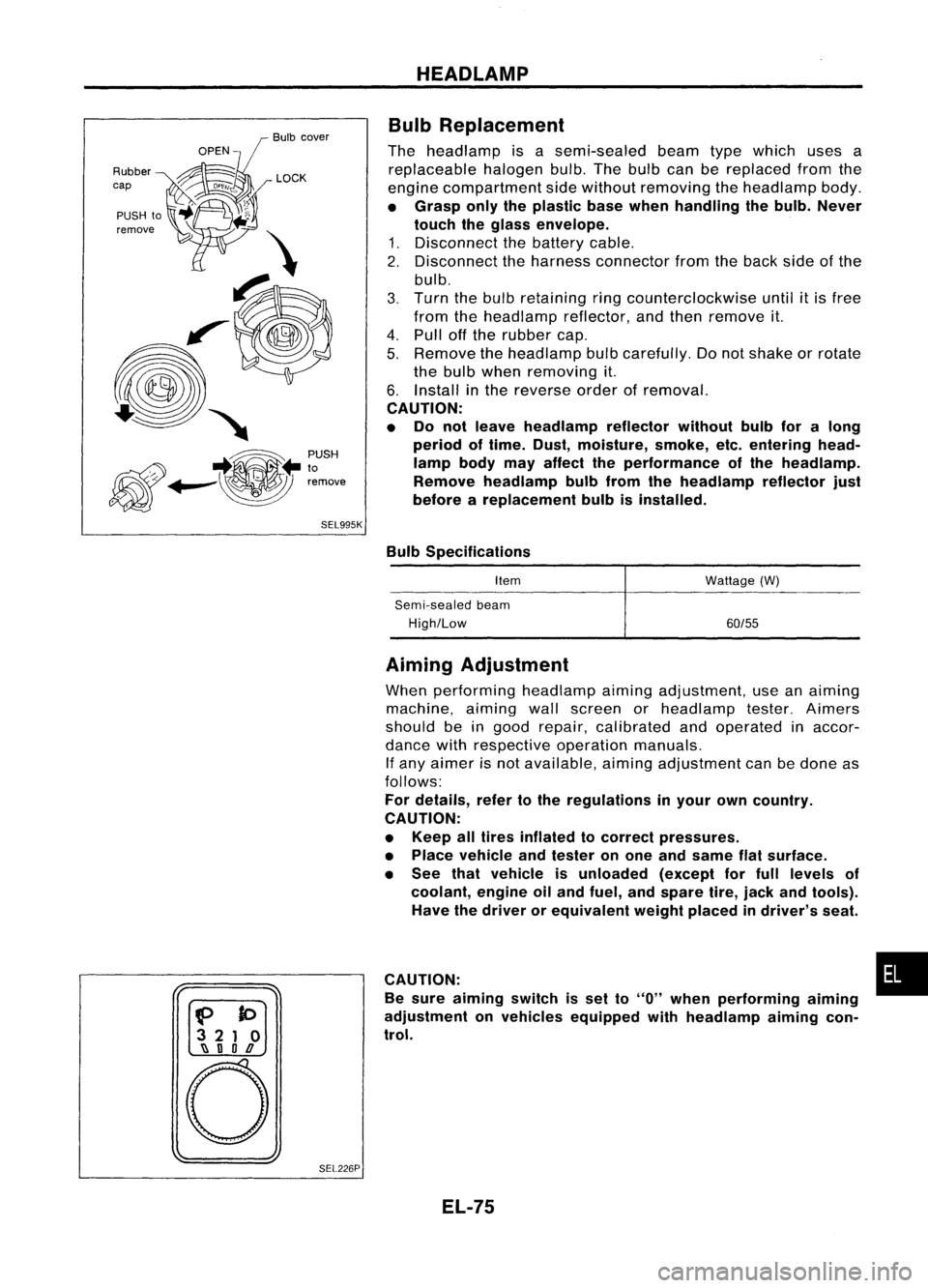
Bulb Replacement
The headlamp isasemi-sealed beamtypewhich usesa
replaceable halogenbulb.Thebulb canbereplaced fromthe
engine compartment sidewithout removing theheadlamp body.
• Grasp onlytheplastic basewhen handling thebulb. Never
touch theglass envelope.
1. Disconnect thebattery cable.
2. Disconnect theharness connector fromtheback sideofthe
bulb.
3. Turn thebulb retaining ringcounterclockwise until
it
is free
from theheadlamp reflector,andthen remove it.
4. Pull offthe rubber cap.
5. Remove theheadlamp bulbcarefully. Donot shake orrotate
the bulb when removing it.
6. Install inthe reverse orderofremoval.
CAUTION:
• Do not leave headlamp reflector withoutbulbforalong
period oftime. Dust,moisture, smoke,etc.entering head-
lamp bodymayaffect theperformance ofthe head lamp.
Remove headlamp bulbfrom thehead lamp reflector just
before areplacement bulbisinstalled.
Bulb Specifications
Item
Semi-sealed beam
High/Low Wattage
(W)
60/55
f>
to
3 21 0
~ nOD
o
SEL226PAiming
Adjustment
When performing headlamp aiming adjustment, useanaiming
machine, aimingwallscreen orheadlamp tester.Aimers
should beingood repair, calibrated andoperated inaccor-
dance withrespective operationmanuals.
If any aimer isnot available, aimingadjustment canbedone as
follows:
For details, refertothe regulations inyour owncountry.
CAUTION:
• Keep alltires inflated tocorrect pressures.
• Place vehicle andtester onone and same flatsurface.
• See thatvehicle isunloaded (exceptforfull levels of
coolant, engineoiland fuel, andspare tire,jack andtools).
Have thedriver orequivalent weightplaced indriver's seat.
CAUTION: •
Be sure aiming switchisset to
"0"
when performing aiming
adjustment onvehicles equipped withheadlamp aiming con-
trol.
EL-75