1995 NISSAN ALMERA N15 heating
[x] Cancel search: heatingPage 17 of 1701

Fluidleakage TROUBLE
DIAGNOSES
Preliminary Check(PriortoRoad Testing)
AIT FLUID CHECK
Fluid leakage check
1. Clean areasuspected ofleaking, -for example, mating
surface ofconverter housingandtransmission case.
2. Start engine, applyfootbrake, placeselector leverin"0"
position andwait afew minutes.
3. Stop engine.
4. Check forfresh leakage.
SAT288G
Fluidcondition check
Fluid levelcheck -Refer toMA section (CHASSIS AND
BODY MAINTENANCE).
Fluid
color
Oark orblack withburned odor
Milky pink
Varnished fluid,lighttodark brown
and tacky Suspected
problem
Wear offrictional material
Water contamination
- Road water entering through
filler tubeorbreather
Oxidation
- Over orunder filling
- Overheating
•
Road Testing
Perform roadtests using "Symptom" chart.Refertopage
AT-20.
"P"
POSITION
1. Place selector leverin"P" position andstart engine. Stop
engine andrepeat theprocedure inall positions, including
neutral position.
2. Stop vehicle onaslight upgrade andplace selector leverin
"P" position. Releaseparkingbraketomake surevehicle
remains locked.
"R"
POSITION
1. Manually moveselector leverfrom"P"to"R", andnote
shift quality.
2. Drive vehicle inreverse longenough todetect slippage or
other abnormalities.
"N"
POSITION
1. Manually moveselector leverfrom"R"and"0"to"N" and
note shift quality.
2. Release parkingbrakewithselector leverin"N" position.
Lightly depress accelerator pedaltomake surevehicle
does notmove. (When vehicle isnew orsoon afterclutches
have been replaced, vehiclemaymove slightly. Thisisnot
a problem.)
AT-17
Page 191 of 1701
__________ PRECAUTIONS ___________
BODYALIGNMENT _
Precautions ForHandling HighStregth Steel Engine
Compartment
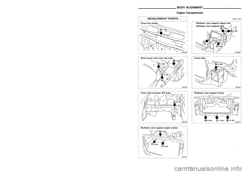
__ MEASURMENT POINTS__
Unit:mm
Front side
SBT088
Traction direction: ...
Not
recommended
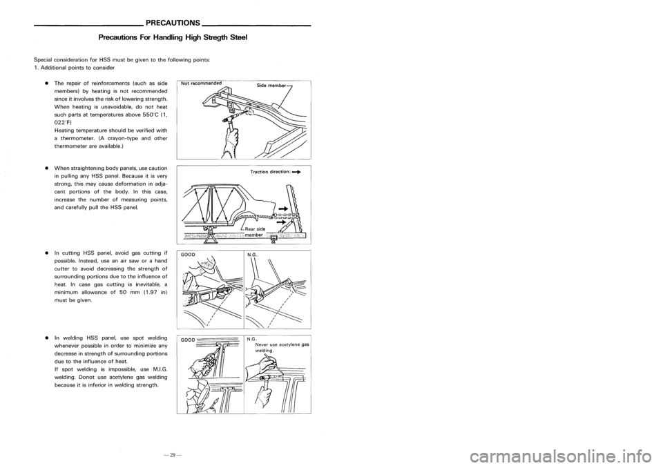
• The repair ofreinforcements (suchasside
members) byheating isnot recommended
since itinvolves theriskoflowering strength.
When heating isunavoidable, donot heat
such parts attemperatures above550°C (1,
022°F)
Heating temperature shouldbeverified with
a thermometer. (Acrayon-type andother
thermometer areavailable.)
• When straightening bodypanels, usecaution
in pulling anyHSS panel. Because itis very
strong, thismay cause deformation inadja-
cent portions ofthe body. Inthis case,
increase thenumber ofmeasuring points,
and carefully pulltheHSS panel.
Special
consideration forHSS must begiven tothe following points:
1 .Additional pointstoconsider
• Incutting HSSpanel, avoidgascutting if
possible. Instead,useanairsaw orahand
cutter toavoid decreasing thestrength of
surrounding portionsduetothe influence of
heat. Incase gascutting isinevitable, a
minimum allowance of50 mm (1.97 in)
must begiven.
SBT090
Radiator
coresupport lower
•
(b)
11
dia.
SBT094
• Inwelding HSSpanel, usespot welding
whenever possibleinorder tominimize any
decrease instrength ofsurrounding portions
due tothe influence ofheat.
If spot welding isimpossible, useM.LG.
welding. Donotuseacetylene gaswelding
because itis inferior inwelding strength.
GOOD
-================
N.G.
Never useacetylene .gas
welding.
Radiator
coresupport uppercenter
SBT091
-29-
-16-
Page 204 of 1701
__________ PRECAUTIONS ___________
BODYALIGNMENT _
Precautions ForHandling HighStregth Steel Engine
Compartment
__ MEASURMENT POINTS__
Unit:mm
Front side
SBT088
Traction direction: ...
Not
recommended
• The repair ofreinforcements (suchasside
members) byheating isnot recommended
since itinvolves theriskoflowering strength.
When heating isunavoidable, donot heat
such parts attemperatures above550°C (1,
022°F)
Heating temperature shouldbeverified with
a thermometer. (Acrayon-type andother
thermometer areavailable.)
• When straightening bodypanels, usecaution
in pulling anyHSS panel. Because itis very
strong, thismay cause deformation inadja-
cent portions ofthe body. Inthis case,
increase thenumber ofmeasuring points,
and carefully pulltheHSS panel.
Special
consideration forHSS must begiven tothe following points:
1 .Additional pointstoconsider
• Incutting HSSpanel, avoidgascutting if
possible. Instead,useanairsaw orahand
cutter toavoid decreasing thestrength of
surrounding portionsduetothe influence of
heat. Incase gascutting isinevitable, a
minimum allowance of50 mm (1.97 in)
must begiven.
SBT090
Radiator
coresupport lower
•
(b)
11
dia.
SBT094
• Inwelding HSSpanel, usespot welding
whenever possibleinorder tominimize any
decrease instrength ofsurrounding portions
due tothe influence ofheat.
If spot welding isimpossible, useM.LG.
welding. Donotuseacetylene gaswelding
because itis inferior inwelding strength.
GOOD
-================
N.G.
Never useacetylene .gas
welding.
Radiator
coresupport uppercenter
SBT091
-29-
-16-
Page 256 of 1701
SEAT
Heated Seat
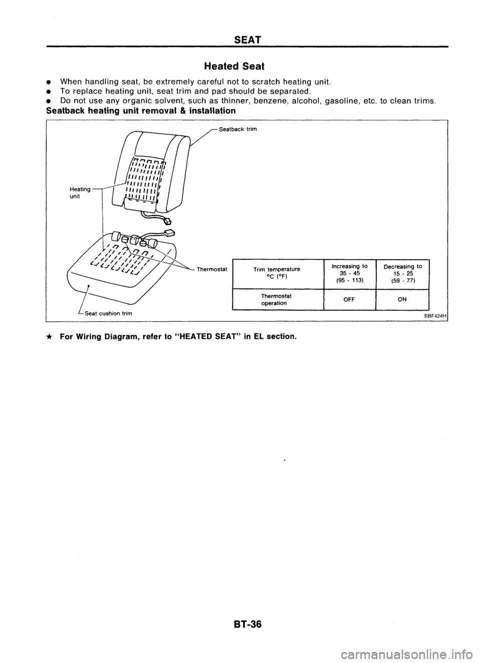
• When handling seat,beextremely carefulnottoscratch heating unit.
• Toreplace heatingunit,seattrimandpadshould beseparated.
• Donot use anyorganic solvent, suchasthinner, benzene, alcohol,gasoline, etc.toclean trims.
Seatback heatingunitremoval
&
installation
Heating
unit Seat
back trim
Trim temperature Increasing
to
Decreasing to
0C (OF) 35
-45
15-25
(95 -113)
(59-77)
Thermostat OFFON
operation
SBF424H
* For Wiring Diagram, referto"HEATED SEAT"inEL section.
8T-36
Page 615 of 1701

AUDIOANDANTENNA
Antenna feeder
(RHO models) Radio
FuseCheck
Location ofAntenna
Antennafeeder
(LHO models)
Antenna RodReplacement
1. Loosen screwssecuring antennabase.
2. Pullout pipefrom antenna base.
Heating thepipe withadrier makes
it
easier.
EL-243 GEL020
•
Page 617 of 1701
![NISSAN ALMERA N15 1995 Service Manual HEATEDSEAT
*
For location ofheating unit,refer to"SEAT" inBT section.
Wiring Diagram -HIS EAT -
EL-H/SEAT-01
IGNITION SWITCH
ON orSTART
FUSEReferto
BLOCK EL-POWER.
(JIB)
(]V
I
R R
w=n NISSAN ALMERA N15 1995 Service Manual HEATEDSEAT
*
For location ofheating unit,refer to"SEAT" inBT section.
Wiring Diagram -HIS EAT -
EL-H/SEAT-01
IGNITION SWITCH
ON orSTART
FUSEReferto
BLOCK EL-POWER.
(JIB)
(]V
I
R R
w=n](/manual-img/5/57349/w960_57349-616.png)
HEATEDSEAT
*
For location ofheating unit,refer to"SEAT" inBT section.
Wiring Diagram -HIS EAT -
EL-H/SEAT-01
IGNITION SWITCH
ON orSTART
FUSEReferto
BLOCK EL-POWER.
(JIB)
(]V
I
R R
w=n w=n
Nextpage
~
lb4=Jl ~~~
B/W B W/BWB
1----1-1::
1
-w-G>
-W/B~
'I-B/W~
II-B/Y~
HI
-
La Rf- -
La -Rf-
LOHEATED
HI
-l5
Rf- -la-Rf-
LOHEATED
SEAT SEAT
•
SWITCH
•
SWITCH
OFF OFF LH
OFFOFF RH
(B13)
~
~
B/Y
f.
B B
~ ~
<[il) ~
Refertolast page •
(Foldout page).
HEL 145
EL-245
Page 765 of 1701
ON-BOARDDIAGNOSTIC SYSTEMDESCRIPTION @KJ
Malfunction Indicatorlamp(Mil)(Cont'd)
DIAGNOSTIC TESTMODE I-BULB CHECK
In this mode, theMALFUNCTION INDICATORLAMPonthe instrument panelshould stayON.Ifitremains
OFF, check thebulb. Refer toEL section ("WARNING LAMPSANDCHIME") orsee EC-223.
DIAGNOSTIC TESTMODE I-MALFUNCTION WARNING
MALFUNCTION INDICATORLAMP
ON
OFF Condition
Engine coolant temperature sensorcircuitmalfunction oroverheating isdetected, or
the ECM's CPUismalfunctioning.
No malfunction.
• These Diagnostic TroubleCodeNumbers areclarified inDiagnostic TestMode II(SELF-DIAGNOS-
TIC RESULTS).
DIAGNOSTIC TESTMODE II-SELF-DIAGNOSTIC RESULTS
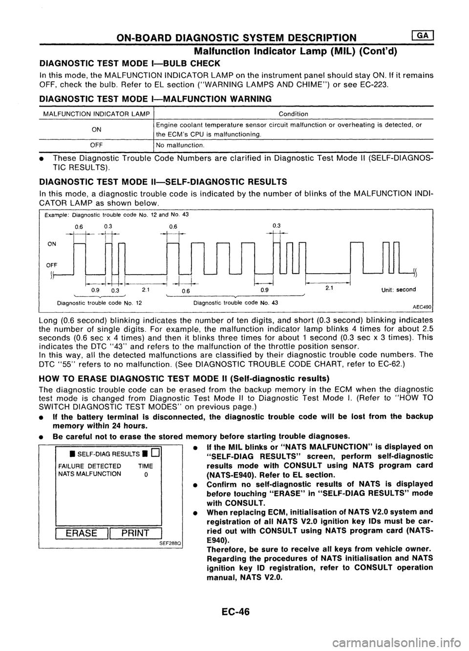
In this mode, adiagnostic troublecodeisindicated bythe number ofblinks ofthe MALFUNCTION INDI-
CATOR LAMPasshown below.
Example: Diagnostic troublecodeNo.12and No.43
ON
0.6
03
111-'1
0.6
II
0.3
OFF
j
~
~~ -I.
--.1
-4--1--
Q9 O~ 21 OB Q9
'--------v----' '--------v------~
Diagnostic troublecodeNo.12 DiagnostictroublecodeNo.43
2.1
Unit:second
AEC490
• SELF-DIAG RESULTS.
0
FAILURE DETECTED TIME
NATS MALFUNCTION
0
I
ERASE
II
PRINT
I
SEF288Q
Long
(0.6second) blinkingindicates thenumber often digits, andshort (0.3second) blinkingindicates
the number ofsingle digits. Forexample, themalfunction indicatorlampblinks 4times forabout 2.5
seconds (0.6secx4 times) andthen itblinks threetimes forabout 1second (0.3secx3 times). This
indicates theDTC "43" andrefers tothe malfunction ofthe throttle position sensor.
In this way, allthe detected malfunctions areclassified bytheir diagnostic troublecodenumbers. The
DTC "55" refers tono malfunction. (SeeDIAGNOSTIC TROUBLECODECHART, refertoEC-62.)
HOW TOERASE DIAGNOSTIC TESTMODE II(Self-diagnostic results)
The diagnostic troublecodecanbeerased fromthebackup memory inthe ECM when thediagnostic
test mode ischanged fromDiagnostic TestMode IIto Diagnostic TestMode
I.
(Refer to"HOW TO
SWITCH DIAGNOSTIC TESTMODES" onprevious page.)
• Ifthe battery terminal isdisconnected, thediagnostic troublecodewillbelost from thebackup
memory within24hours.
• Becareful nottoerase thestored memory before
startin~
troublediagnoses.
• If
the MIL blinks or"NATS MALFUNCTION" isdisplayed on
"SELF-OIAG RESULTS"screen,perform self-diagnostic
results modewithCONSULT usingNATS program card
(NATS-E940). RefertoEL section.
• Confirm noself-diagnostic resultsofNATS isdisplayed
before touching "ERASE" in"SELF-DIAG RESULTS"mode
with CONSULT.
• When replacing ECM,initialisation ofNATS V2.0system and
registration ofall NATS V2.0ignition key10smust becar-
ried outwith CONSULT usingNATS program card(NATS-
E940).
Therefore, besure toreceive allkeys from vehicle owner.
Regarding theprocedures ofNATS initialisation andNATS
ignition key10registration, refertoCONSULT operation
manual, NATS V2.0.
EC-46
Page 1360 of 1701
PRECAUTIONS
Engine Oils(ConI' d)
• Wash withsoap andwater toensure alloil isremoved (skin
cleansers andnailbrushes willhelp). Preparations contain-
ing lanolin replace thenatural skinoilswhich havebeen
removed.
• Donot use gasoline, kerosine, dieselfuel,gasoil,thinners
or solvents forcleaning skin.
• If
skin disorders develop,obtainmedical advicewithout
delay.
• Where practicable, degreasecomponents priortohandling.
• Where thereisarisk ofeye contact, eyeprotection should
be worn, forexample, chemicalgogglesorface shields; in
addition aneye wash facility should beprovided.
ENVIRONMENTAL PROTECTIONPRECAUTIONS
Burning usedengine oilinsmall space heaters orboilers can
be recommended onlyforunits ofapproved design.Theheat-
ing system mustmeettherequirements ofHM Inspectorate of
Pollution forsmall burners ofless than 0.4MW. Ifin doubt check
with theappropriate localauthority and/ormanufacturer ofthe
approved appliance.
Dispose ofused oiland used oilfilters through authorized
waste disposal contractors tolicensed wastedisposal sites,or
to the waste oilreclamation trade.Ifin doubt, contact thelocal
authority foradvice ondisposal facilities.
It is illegal topour used oilontothe ground, downsewers or
drains, orinto water courses.
The regulations concerningthepollution ofthe environment
will vary between regions.
Precautions forFuel
GASOLINE ENGINE:
For Europe
Unleaded gasolineofat least 95octane (RON)
CAUTION: Do not use leaded gasoline. Usingleaded gasoline willdamage
the catalytic converter.
Except Europe
Unleaded gasolineofat least 91octane (RON)
DIESEL ENGINE*:
Diesel fuelofat least 50cetane
If two types ofdiesel fuelareavailable, usesummer or
winter fuelproperly according tothe following temperature
conditions.
• Above -rc(20°F) Summer typediesel fuel.
• Below
-rc
(20°F) Wintertypediesel fuel.
CAUTION:
• Donot use home heating oil,gasoline, orother alternate
fuels inyour diesel engine. Theuseofthose cancause
engine damage.
• Donot use summer fuelattemperature below_7°C(20°F).
The cold temperatures willcause waxtoform inthe fuel. As
a result, itmay prevent theengine fromrunning smoothly.
• Donot add gasoline orother alternate fuelstodiesel fuel.
GI-6