Page 1375 of 1701

HOWTOPERFORM EFFICIENT DIAGNOSIS FORANELECTRICAL INCIDENT
Incident Simulation Tests(Cont'd)
Engine compartment
There areseveral reasons avehicle orengine vibration could•
cause anelectrical complaint. Someofthe things tocheck for
are:
• Connectors notfully seated.
• Wiring harness notlong enough andisbeing stressed due
to engine vibrations orrocking.
• Wires laying across brackets ormoving components.
• Loose, dirtyorcorroded groundwires.
• Wires routed tooclose tohot components.
To inspect components underthehood, startbyverifying the
integrity ofground connections. (RefertoGROUND INSPEC-
TION described later.)Firstcheck thatthesystem isproperly
grounded. Thencheck forloose connection by
gently shaking
the wiring orcomponents aspreviously explained. Usingthe
wiring diagrams inspectthewiring forcontinuity.
Behind theinstrument panel
An improperly routedorimproperly clampedharnesscan
become pinchedduringaccessory installation. Vehiclevibra-
tion canaggravate aharness whichisrouted alongabracket
or near ascrew.
Under seating areas
An unclamped orloose harness cancause wiring tobe pinched
by seat components (suchasslide guides) duringvehicle vibra-
tion. Ifthe wiring runsunder seating areas,inspect wirerout-
ing forpossible damageorpinching.
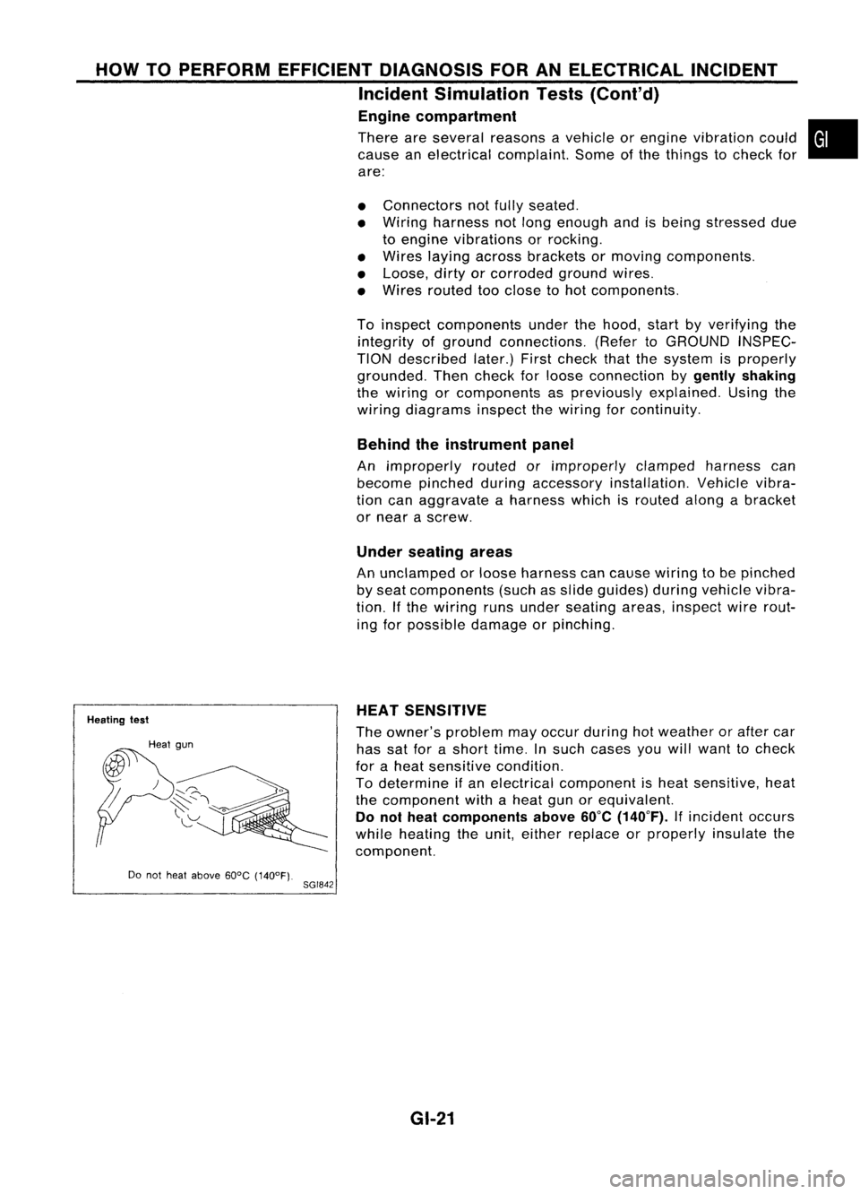
Heating test
Do not heat above 60°C(140°F).
8GI842 HEAT
SENSITIVE
The owner's problem mayoccur during hotweather orafter car
has satforashort time.Insuch cases youwillwant tocheck
for aheat sensitive condition.
To determine ifan electrical component isheat sensitive, heat
the component withaheat gunorequivalent.
Do not heat components above
60°C
(140°F).
Ifincident occurs
while heating theunit, either replace orproperly insulatethe
component.
GI-21
Page 1416 of 1701

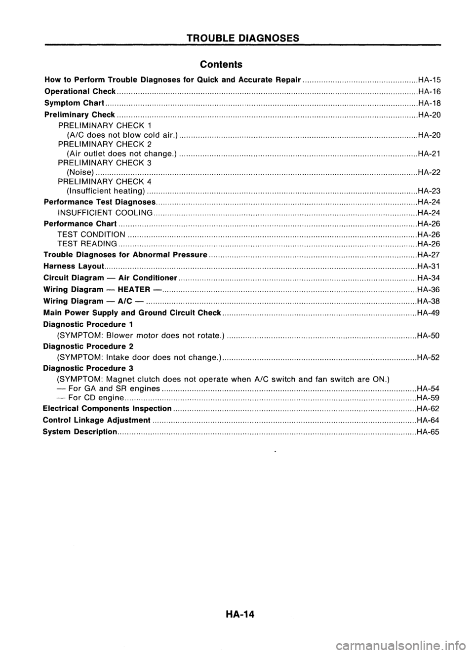
TROUBLEDIAGNOSES
Contents
How toPerform TroubleDiagnoses forQuick andAccurate Repair HA-15
Operational Check HA-16
Symptom Chart HA-18
Preliminary Check HA-20
PRELIMINARY CHECK1
(A/C
does notblow coldair.) HA-20
PRELIMINARY CHECK2
(Air outlet doesnotchange.) HA-21
PRELIMINARY CHECK3
(Noise) HA-22
PRELIMINARY CHECK4
(I nsufficient heating) HA-23
Performance TestDiagnoses HA-24
INSUFFICIENT COOLING HA-24
Performance Chart HA-26
TEST CONDITION HA-26
TEST READING HA-26
Trouble Diagnoses forAbnormal Pressure HA-27
Harness Layout. HA-31
Circuit Diagram -Air Conditioner HA-34
Wiring Diagram -HEATER - HA-36
Wiring Diagram -AIC - HA-38
Main Power Supply andGround CircuitCheck HA-49
Diagnostic Procedure1
(SYMPTOM: Blowermotordoesnotrotate.) HA-50
Diagnostic Procedure2
(SYMPTOM: Intake doordoes notchange.) HA-52
Diagnostic Procedure3
(SYMPTOM: Magnetclutchdoesnotoperate when
A/C
switch andfanswitch areON.)
- For GAand SRengines HA-54
- For CDengine HA-59
Electrical Components Inspection HA-62
Control Linkage Adjustment HA-64
System Description HA-65
HA-14
Page 1420 of 1701

TROUBLEDIAGNOSES
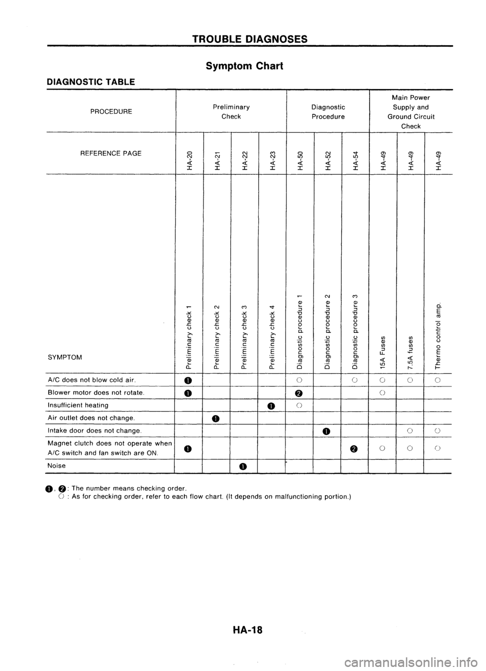
Symptom Chart
DIAGNOSTIC TABLE
MainPower
PROCEDURE Preliminary
DiagnosticSupplyand
Check ProcedureGroundCircuit
Check
REFERENCE PAGE
0
N
N
C')
0 N
"'"
O'J
O'JO'J
N NN
LO LO
LO
"'""'""'"
.d: .d:.d: .d:.d:
I
.d: .d:.d:
.d:
~
:c :c:c :c
:c :c:c :c:c:c
~
N
C')
Q) Q)Q)
ci.
~
N
C')
"'" ....
....
....
:J :J:J
E
-'" -'"-'" -'"
"0
"0"0
u uu u
Q)Q) Q)
«l
Q) Q)Q) Q)
uuu
e
.c
.c.c .c
000
u uu u
....
........
>.
~
>.
>.
0.
0.0.
C
~
....
....
uu u
UJ UJ
0
«l «l
«l
~ ~~
OJ
Q)
u
c cc
c
UJUJ
0
.-
.-
.-
000
:J
.2
E E
E E
ccc
u..
E
SYMPTOM
.-
-
.
-
OJOJOJ
~
....
~
OJ
Qj
Qj
«l«l
«l
~ Q)
.... .... ....
Ci Ci Ci
LO
LO
.c
a.. a..a..
a..
~
r--
f-
AIC
does notblow coldair.
0
0
0
0
00
Blower motordoesnotrotate.
0
fj
()
Insufficient heating
0
()
Air outlet doesnotchange.
0
Intake doordoes notchange.
0
0
0
Magnet clutchdoesnotoperate when
0
fj
0
0
0
AIC
switch andfanswitch areON.
Noise
0
0,
fj:
The number meanschecking order.
C :
As for checking order,refertoeach flowchart. (Itdepends onmalfunctioning portion.)
HA-18
Page 1425 of 1701

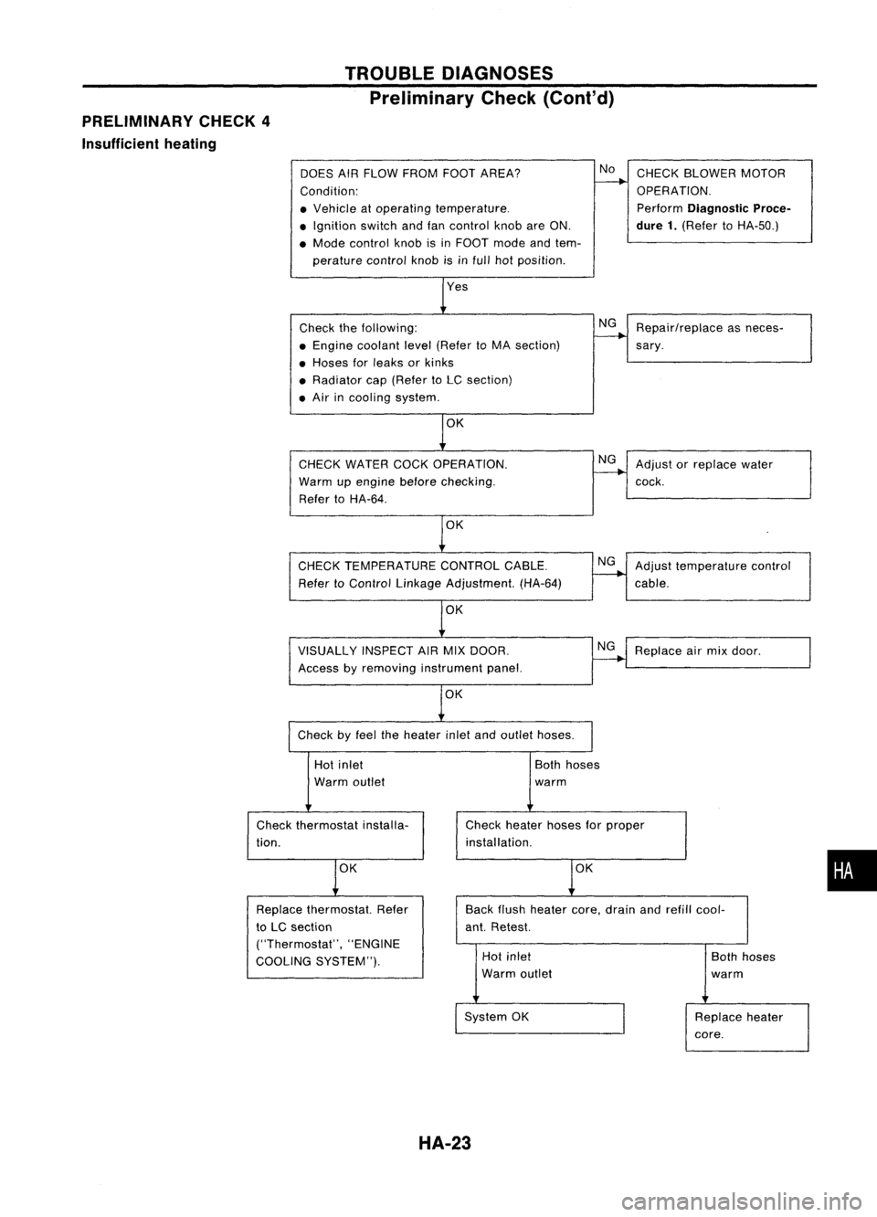
PRELIMINARY CHECK4
Insufficient heating TROUBLE
DIAGNOSES
Preliminary Check(Cont'd)
DOES AIRFLOW FROM FOOTAREA?
Condition:
• Vehicle atoperating temperature .
• Ignition switchandfancontrol knobareON.
• Mode control knobisin FOOT modeandtem-
perature controlknobisinfull hotposition.
Check thefollowing:
• Engine coolant level(Refer toMA section)
• Hoses forleaks orkinks
• Radiator cap(Refer toLC section)
• Air incooling system.
CHECK WATER COCKOPERATION.
Warm upengine before
checking.
Refer toHA-64.
OK
CHECK TEMPERATURE CONTROLCABLE.
Refer toControl Linkage Adjustment. (HA-64)
VISUALLY INSPECTAIRMIX DOOR.
Access byremoving instrument panel.
OK
Check byfeel theheater inletandoutlet hoses.
No
NG
NG
NG
NG
CHECK
BLOWER MOTOR
OPERATION.
Perform
Diagnostic Proce-
dure 1.
(Refer toHA-50.)
Repair/replace asneces-
sary .
Adjust orreplace water
cock.
Adjust temperature control
cable.
Replace airmix door.
Hot inlet
Warm outlet
Check thermostat installa-
tion.
OK
Both
hoses
warm
Check heater hosesforproper
installation.
OK
•
Back
flush heater core,drain andrefill cool-
ant. Retest.
Replace
thermostat. Refer
to LC section
("Thermostat", "ENGINE
COOLING SYSTEM"). Hot
inlet
Warm outlet
System OK
HA-23
Both
hoses
warm
Replace heater
core.