Page 1 of 1701

AUTOMATICTRANSAXLE
SECTION
AT
CONTENTS
PREPARATION ANDPRECAUTIONS
3
Special Service Tools 3
Commercial ServiceTools 6
Service Notice 7
Supplemental RestraintSystem(SRS)"AIR
BAG" (DualAirBag System) 7
Supplemental RestraintSystem(SRS)"AIR
BAG" (Single AirBag System) 7
DESCRIPTION
8
Cross-sectional View 8
Hydraulic ControlCircuit 10
Shift Mechanism 14
Control System 15
TROUBLE DIAGNOSES 17
Preliminary Check(PriortoRoad Testing) 17
Road Testing 17
Stall Tasting 24
Pressure Testing 26
Wiring Diagram -AT - 28
Electrical Components Inspection 30
ON-VEHICLE SERVICE 31
Control ValveAssembly andAccumulator 31
Throttle WireAdjustment.. 33
Control CableInstallation andAdjustment 35
Governor Valve 36
Inhibitor SwitchAdjustment 37
Differential SideOilSeal Replacement.. 37
REMOVAL ANDINSTALLATION
39
Removal 39
Installation .40MAJOR
OVERHAUL.. 42
All Models 42
Except Model34X81 .44
Model 34X81 45•
Shift Control Components 46
i
Oil Channel 47
Locations ofAdjusting Shims,Needle
Bearings, ThrustWashers andSnap Rings -
Except Model34X81 .48
Locations ofAdjusting Shims,Needle
Bearings, ThrustWashers andSnap Rings -
Model 34X81 .49
DiSASSEMBLy 50
REPAIR FORCOMPONENT PARTS 66
Manual ShaftandThrottle Lever 66
Oil Pump 70
Control ValveAssembly 74
Control ValveUpper Body 86
Control ValveLower Body 90
Reverse Clutch 93
High Clutch 97
Forward ClutchandOverrun Clutch 102
Low &Reverse Brake 108
Rear Internal Gear,Forward ClutchHuband
Overrun ClutchHub 112
Output Shaft,Output Gear,IdlerGear,
Reduction PinionGearandBearing Retainer
- Except Model34X81 116
Output Shaft,IdlerGear, Reduction Pinion
Gear andBearing Retainer -Model 34X81 121
Band Servo Piston Assembly 126
Final Drive -Except Model34X81 131
Final Drive -Model 34X81 135
Page 48 of 1701
MAJOROVERHAUL
Locations ofAdjusting Shims,Needle Bearings,
Thrust Washers andSnap Rings -Except
Model 34X81
Outer diameter andcolor ofthrust washers
Outerandinner diameter ofneedle bearings
Outer
&
inner diameter ofbearing races,adjusting shimsand
adjusting spacer
Item
number
@
@
Outer
diameter mm(inl
72.012.8351
78.5 13.091)
Color
black
Item
number Outer
diameter
Innerdiameter
mm(in)
mm(in)
47.0 (1.8501
32.0(1.2601
35011.3781 20.110.7911
60.012.3621 42.00.6541
60.0 (2.362)
45.011.7721
47.011.850) 30011.1811
42.6 0.677)
26.10.0281
48.0 (1890)
33.511.319)
54.0 121261
40.111.5791
Outer diameter Inner
diameter
Item number
mmlinl mm
(in)
@
48.00.8901 33.0
(1.299)
@
29.011.1421 25.0(0.9841
@
34.5
(358)
26.111.0281
@
79.5
13.1301 72.012.835)
~
55.012.165)
42.0(1.654)
*:
Select proper thickness. Outer
diameter ofsnap rings
Item number
Outerdiameter
mmlin)
Q.
142.0
(5.591
CV
113.0
(4.451
@
162.4
(6391
@
135.4
15.331
CID
126.0
(4.961
@
161.516.361
AT-48 SAT510H
Page 49 of 1701
Outerdiameter andcolor ofthrust washers
MAJOR
OVERHAUL
Locations ofAdjusting Shims,Needle Bearings,
Thrust Washers andSnap Rings -Model 34X81
Outer
&
inner diameter ofneedle bearings
Item number Outer
diameter mm(in)
CD
142.0
(5.59)
ClJ
113.0
(4.45)
0
162.4
(6.39)
0
135.4
(5.33)
~ 161.5
(6.36)
@
126.0
(4.96)
(j)
40.5
(1.594)
Outer
diameter ofsnap rings
Item
number Outer
diameter
Color
mm (in)
@
72.0(2.835)
Black
@ 78.5
(3.091)
* :
Select proper thickness.
Outer
&
inner diameter ofbearing raceandadjusting shims
Item number Outer
diameter
Innerdiameter
mm (in)
mm(in)
@
48.0(1.890)
33.0(1.299)
@
72.0(2.835) 61.0(2.402)
@
34.5(1358) 26.1
(1.028)
@ 68.0
(2.677)
60.0(2.362)
Item
number Outer
diameter
mm (in)
47.0 (1.850)
35.0 (1.378)
60.0 (2.362)
60.0 (2.362)
47.0 (1.850)
42.6 (1.677)
48.0 (1.890)
55.0 (2.165)
60.0 (2.362)
Inner
diameter
mm (in)
32.0 (1.260)
20.0 (0.787)
42.0 (1.654)
45.0 (1.772)
30.0 (1.181)
26.1 (1.028)
33.5 (1.319)
40.5 (1.594)
40.1 (1.579)
•
SAT106EC
AT-49
Page 1177 of 1701
SLC904
CD
@
10~~103~ \
~' ENGINE
COOLING SYSTEM
I
GA, SR,CD
I
Radiator (Aluminum type)(Cont'd)
4. Caulk tankinspecified sequence withTool.
•
Keep toolperpendicular to
the radiator.
o
X
(Grip isinsufficient.)
SLC896
• Use pliers inthe locations whereToolcannot beused.
5. Make surethattherim iscompletely crimpeddown.
Standard height
"H":
8.0 -8.4 mm (0.315 -0.331 in)
6. Confirm thatthere isno leakage.
Refer toInspection.
INSPECTION
Apply pressure withTool.
Specified pressurevalue:
157 kPa (1.57 bar,1.6kg/cm
2,
23psi)
WARNING:
To prevent therisk ofthe hose coming undonewhileunder
pressure, securelyfastenitdown withahose clamp.
Attach ahose tothe oilcooler aswell.
(A
IT models only)
SLC933 LC-39
Page 1358 of 1701

SEF289HSGI233
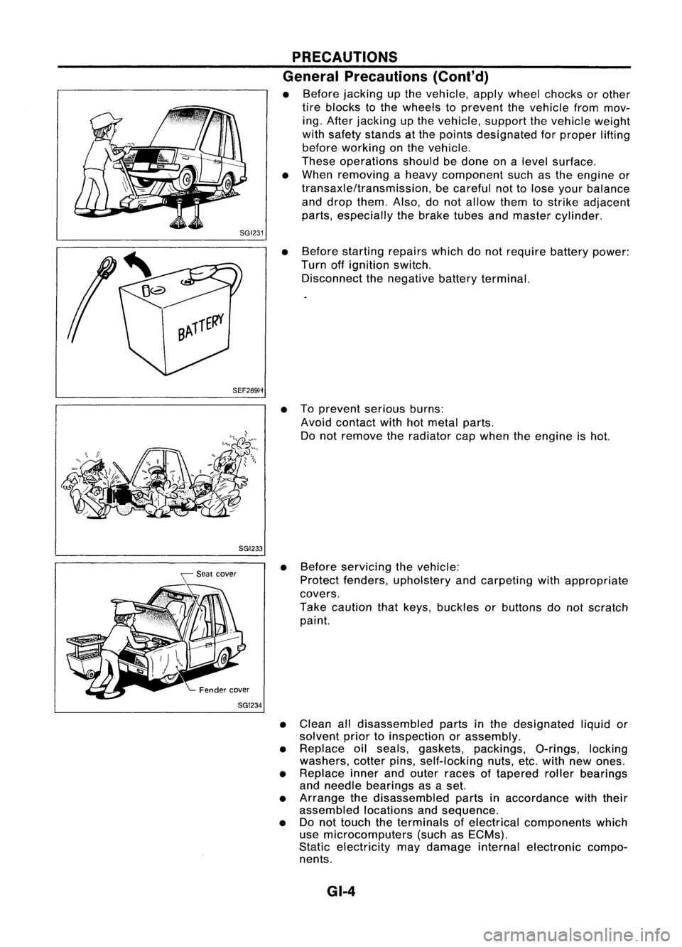
SGI234 PRECAUTIONS
General Precautions (Cont'd)
• Before jacking upthe vehicle, applywheel chocks orother
tire blocks tothe wheels toprevent thevehicle frommov-
ing. After jacking upthe vehicle, supportthevehicle weight
with safety stands atthe points designated forproper lifting
before working onthe vehicle.
These operations shouldbedone onalevel surface.
• When removing aheavy component suchasthe engine or
transaxle/transmission, becareful nottolose your balance
and drop them. Also,donot allow themtostrike adjacent
parts, especially thebrake tubesandmaster cylinder.
• Before starting repairswhichdonot require batterypower:
Turn offignition switch.
Disconnect thenegative batteryterminal.
• Toprevent seriousburns:
Avoid contact withhotmetal parts.
Do not remove theradiator capwhen theengine ishot.
• Before servicing thevehicle:
Protect fenders, upholstery andcarpeting withappropriate
covers.
Take caution thatkeys, buckles orbuttons donot scratch
paint.
• Clean alldisassembled partsinthe designated liquidor
solvent priortoinspection orassembly.
• Replace oilseals, gaskets, packings, O-rings,locking
washers, cotterpins,self-locking nuts,etc.with newones.
• Replace innerandouter races oftapered rollerbearings
and needle bearings asaset.
• Arrange thedisassembled partsinaccordance withtheir
assembled locationsandsequence.
• Donot touch theterminals ofelectrical components which
use microcomputers (suchasECMs).
Static electricity maydamage internalelectronic compo-
nents.
GI-4
Page 1538 of 1701
CHASSISANDBODY MAINTENANCE
Checking BodyCorrosion
Visually checkthebody sheet metalpanelforcorrosion, paintdamage (scratches, chipping,rubbing,
etc.) ordamage tothe anti-corrosion materials.Inparticular, checkthefollowing locations.
Hemmed portion
Hood frontend,door lower end,trunk lidrear end, etc.
Panel joint
Side sillofrear fender andcenter pillar,rearwheel housing ofrear fender, aroundstruttower inengine
compartment, etc.
Panel edge
Trunk lidopening, sunroofopening, fenderwheelarch flange,fuelfiller lidflange, around holesinpanel,
etc.
Parts contact
Waist molding, windshield molding,bump.er,etc.
Protectors
Damage orcondition ofmudguard, fenderprotector, chippingprotector, etc.
Anti-corrosion materials
Damage orseparation ofanti-corrosion materialsunderthebody.
Drain holes
Condition ofdrain holes atdoor andside sill.
When repairing corrodedareas,refertothe Corrosion RepairManual.
MA-52