1995 NISSAN ALMERA N15 Check light wiring
[x] Cancel search: Check light wiringPage 373 of 1701

ELECTRICALSYSTEM
SECTION
EL
When youread wiring diagrams:
• Read GIsection, "HOWTOREAD WIRING DIAGRAMS".
When youperform troublediagnos.es, readGIsection, "HOWTOFOllOW FLOWCHART
IN TROUBLE DIAGNOSES" and"HOW TOPERFORM EFFICIENT DIAGNOSIS FORAN
ELECTRICAL INCIDENT".
CONTENTS
PRECAUTIONS 4
Supplemental RestraintSystem(SRS)"AIR
BAG" (DualAirBag System) 4
Supplemental RestraintSystem(SRS)"AIR
BAG" (Single AirBag System) 4
HARNESS CONNECTOR 5
Description 5
STANDARDIZED RELAy 6
Description 6
POWER SUPPLY ROUTING 8
Schematic 8
Wiring Diagram -POWER - 10
Fuse 19
Fusible Link 19
Circuit Breaker 19
GROUND DISTRIBUTION 20
BATTERy 25
How toHandle Battery 25
Battery TestandCharging Chart.. 28
Service DataandSpecifications (SOS) 32
STARTING SySTEM
33
Wiring Diagram -START - 33
Trouble Diagnoses 35
Construction 36
Removal andInstallation .45
Magnetic SwitchCheck .46
Pinion/Clutch Check 46
Brush Check 46
Yoke Check 47
Armature Check 48
Assembly .49
Service DataandSpecifications (SDS) 50
CHARGING SYSTEM 52
Wiring Diagram -CHARGE - 52
Trouble Diagnoses 54Construction
55
Removal andInstallation 57
Disassembly 57
Rotor Check 57
Brush Check 58
Stator Check 58
Diode Check 59
Assembly 60
Service DataandSpecifications (SDS) 61
COMBINATION SWITCH 62
Combination Switch/Check 62
Replacement 64
HEADLAMP -Without Daytime lightSystem -65
Wiring Diagram -H/LAMP - 65
Trouble Diagnoses 67
HEADLAMP -Daytime lightSystem - 68
Operation (Daytimelightsystem) 68
System Description 69
Schematic 70
Wiring Diagram -DTRL - 71
Trouble Diagnoses (DaytimeLight) 74
HEADLAMP 75
Bulb Replacement... 75•
Aiming Adjustment. 75
HEADLAMP -Headlamp Aiming
Control- 77
Wiring Diagram -AIM - 77
Description 81
EXTERIOR LAMP 82
Clearance, LicenseandTail Lamps/Schematic 82
Clearance, LicenseandTail Lamps/Wiring
Diagram -TAILIL - 83
Stop Lamp/Wiring Diagram-STOP/L - 92
Back-up Lamp/Wiring Diagram-BACK/L -94
Front FogLamp/Wiring Diagram-F/FOG -96
Front FogLamp BulbReplacement 101
Page 374 of 1701

CONTENTS(Conl'd.)
Front FogLamp Aiming Adjustment.. 101
Rear FogLamp/Wiring Diagram-R/FOG -102
Turn Signal andHazard Warning Lamps/
Schematic 106
Turn Signal andHazard Warning
Lamps/Wiring Diagram-TURN - 107
Turn Signal andHazard Warning
Lamps/Trouble Diagnoses 113
Combination FlasherUnitCheck 113
Bulb Specifications 114
INTERIOR LAMP 115
Illumination/Schematic 115
Illumination/Wiring Diagram-ILL - 116
Interior, Spot,Trunk Room andLuggage
Room Lamps/Wiring Diagram-INT/L - 122
Bulb Specifications 126
METER ANDGAUGES 127
Combination Meter 127
Speedometer, Tachometer,Temp.andFuel
Gauges/Wiring Diagram-METER - 129
Inspection/Fuel GaugeandWater
Temperature Gauge 133
Inspection/Tachometer 134
Inspection/Speedometer andVehicle Speed
Sensor 135
Fuel Tank Gauge UnitCheck 137
Thermal Transmitter Check 137
Vehicle SpeedSensor SignalCheck 137
WARNING LAMPSANDBUZZER 138
Warning Lamps/Schematic 138
Warning Lamps/Wiring Diagram-WARN -139
Oil Pressure SwitchCheck 151
Fuel Warning LampSensor Check 151
Diode Check 151
Warning BuzzerUnit... 151
Warning Buzzer/System Description 152
Warning Buzzer/Wiring Diagram
- BUZZER - 154
Components Inspection-Warning Buzzer 157
WIPER ANDWASHER 160
Front Wiper andWasher/System Description160
Front Wiper andWasher/Wiring Diagram
- WIPER - 162
Front Wiper Amplifier Check 166
Front Wiper Installation andAdjustment.. 166
Front Wiper Linkage 167
Front Washer NozzleAdjustment... 168
Front Washer TubeLayout 168
Rear Wiper andWasher/System Description169Rear
Wiper andWasher/Wiring Diagram
- WIP/R - 171
Rear Wiper Amplifier Check 175
Rear Wiper Installation andAdjustment.. 175
Rear Washer NozzleAdjustment 175
Rear Washer TubeLayout.. 176
Check Valve(forrear washer) 176
Headlamp WiperandWasher/Wiring Diagram
- HLC - 177
Headlamp WiperMotorCheck 179
Headlamp WiperInstallation 179
Headlamp WasherTubeLayout.. 179
Check Valve(Forheadlamp washer) 179
POWER WINDOW 180
System Description 180
Schematic 183
Wiring Diagram -WINDOW - 185
Trouble Diagnoses 197
POWER DOORLOCK 198
System Description 198
Schematic 200
Wiring Diagram -D/LOCK - 202
Trouble Diagnoses -Type 1(For Europe and
Austral ia) 212
Trouble Diagnoses -Type 2(Except for
Europe andAustralia) 216
POWER DOORMIRROR 220
Wiring Diagram -MIRROR - 220
ELECTRIC SUNROOF 224
Wiring Diagram -SROOF - 224
HORN, CIGARETTE LIGHTERANDCLOCK 226
Wiring Diagram -HORN - 226
REAR WINDOW DEFOGGER ANDDOOR
MIRROR DEFOGGER 230
System Description (Formodels withdaytime
light system) 230
Wirin.g Diagram -DEF - 231
Filament Check 235
Fi lament Repai
r
236
AUDIO ANDANTENNA 237
Audio/System Description 237
Wiring Diagram -AUDIO - 238
Radio FuseCheck 243
Location ofAntenna 243
Antenna RodReplacement.. 243
HEATED SEAT 245
Wiring Diagram -H/SEAT - 245
NATS (Nissan Anti-Theft System) 247
System Description 247
System Composition 247
Page 784 of 1701

TROUBLEDIAGNOSIS -General Description
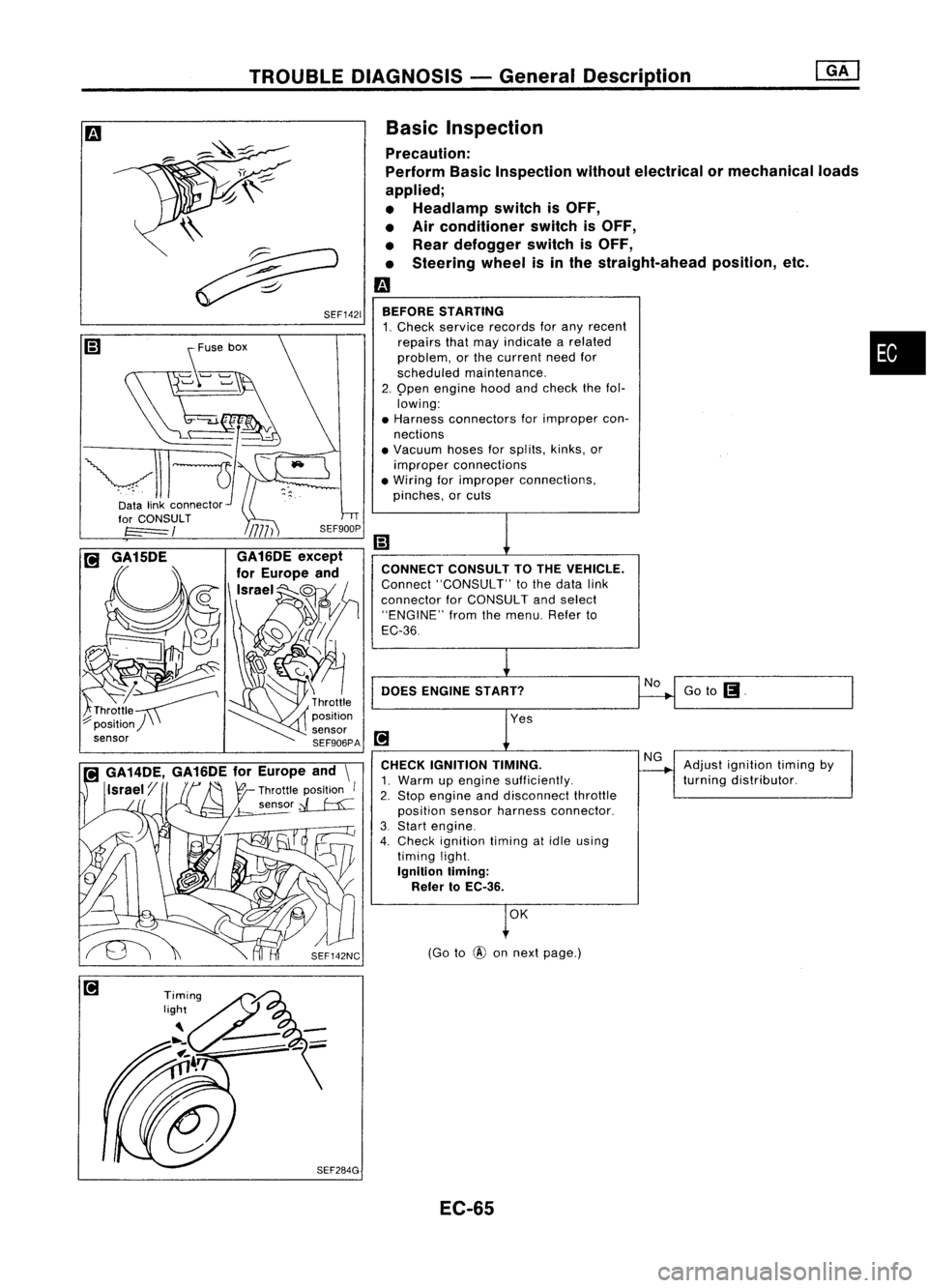
Goto
(J.
Adjust ignition timingby
turning distributor.
No
NG
(Go to
@
onnext page.)
OK
CONNECT
CONSULTTOTHE VEHICLE.
Connect "CONSULT" tothe data link
connector forCONSULT andselect
"ENGINE" fromthemenu. Referto
EC-36
DOES ENGINE START?
BEFORE
STARTING
1. Check service records forany recent
repairs thatmay indicate arelated •
problem, orthe current needfor
scheduled maintenance.
2. 9pen engine hoodandcheck thefol.
lowing:
• Harness connectors forimproper con-
nections
• Vacuum hosesforsplits, kinks,or
improper connections
• Wiring forimproper connections,
pinches, orcuts
CHECK IGNITION TIMING.
1. Warm upengine sufficiently.
2. Stop engine anddisconnect throttle
position sensorharness connector.
3. Start engine.
4. Check ignition timingatidle using
timing light.
Ignition liming:
Refer toEC-36.
Basic
Inspection
Precaution:
Perform BasicInspection withoutelectrical or
mechanical loads
applied;
• Headlamp switchisOFF,
• Air conditioner switchisOFF,
• Rear defogger switchisOFF,
• Steering wheelisin the straight-ahead position,etc.
m
\\
~
~ SEF1421
~use box
~-~
vll-JI-
Datalinkconnector~'
EC-65
Page 990 of 1701

TROUBLEDIAGNOSIS -General Descrip_ti_on
1S_R_'
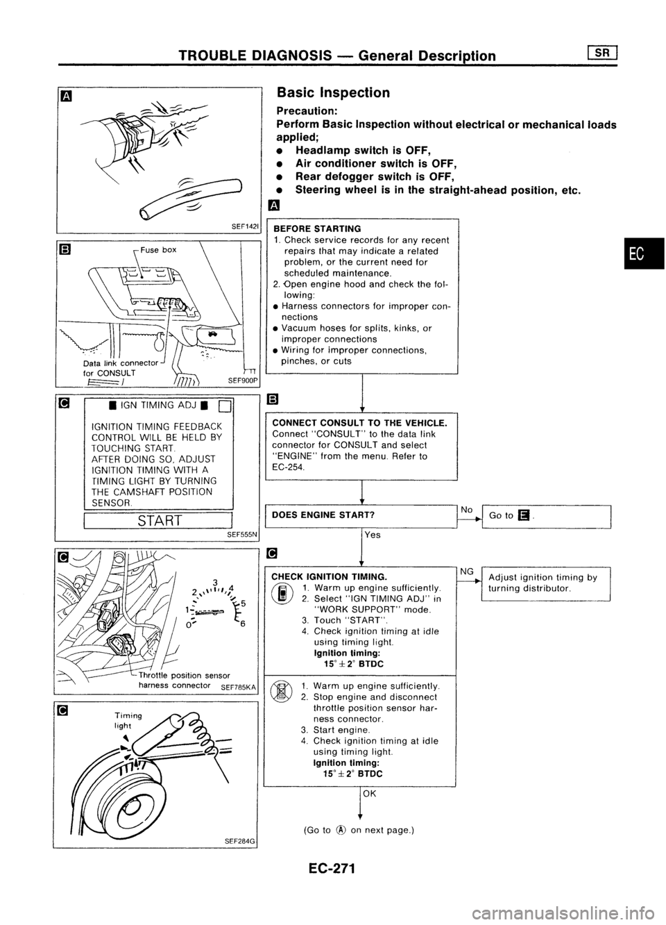
Basic Inspection
Precaution:
Perform BasicInspection withoutelectrical ormechanical loads
applied;
• Headlamp switchisOFF,
• Air conditioner switchisOFF,
• Rear defogger switchisOFF,
• Steering wheelisinthe straight-ahead position,etc.
m
BEFORE STARTING
1. Check service records forany recent •
repairs thatmay indicate arelated
problem, orthe current needfor
scheduled maintenance.
2. Open engine hoodandcheck thefol-
lowing:
• Harness connectors forimproper con-
nections
• Vacuum hosesforsplits, kinks,or
improper connections
• Wiring forimproper connections,
pinches, orcuts
Goto
(I.
No
CONNECT
CONSULTTOTHE VEHICLE.
Connect "CONSULT" tothe data link
connector forCONSULT andselect
"ENGINE" fromthemenu. Referto
EC-254.
DOES ENGINE START?
\\
~
~ SEF1421
START
•
IGN TIMING ADJ.
0
IGNITION TIMINGFEEDBACK
CONTROL WILLBEHELD BY
TOUCHING START
AFTER DOING SO,ADJUST
IGNITION TIMINGWITHA
TIMING LIGHTBYTURNING
THE CAMSHAFT POSITION
SENSOR.
SEF555N
Yes
CHECK IGNITION TIMING.
(ij\
1.Warm upengine sufficiently.
~ 2.Select "IGNTIMING ADJ"in
"WORK SUPPORT" mode.
3. Touch "START".
4. Check ignition timingatidle
using timing light.
Ignition timing:
15°::f:2° BTDC
~ 1Warm upengine sufficiently.
~ 2:
Stop engine anddisconnect
throttle position sensorhar-
ness connector.
3. Start engine.
4. Check ignition timingatidle
using timing light.
Ignition timing:
15°::f:2° BTDC
OK
(Go to
@
onnext page.) Adjust
ignition timingby
turning distributor.
EC-271
Page 1373 of 1701

HOWTOPERFORM EFFICIENT DIAGNOSIS FORANELECTRICAL INCIDENT
Incident Simulation Tests
INTRODUCTION
Sometimes thesymptom isnot present whenthevehicle isbrought infor service.
If
possible, re-create
the conditions presentatthe time ofthe incident. Doingsomay help avoid aNo Trouble FoundDiag-
nosis. Thefollowing sectionillustrates waystosimulate theconditionslenvironment underwhich the
owner experiences anelectrical incident.
The section isbroken intothesixfollowing topics:
• Vehicle vibration
• Heat sensitive
• Freezing
• Water intrusion
• Electrical load
• Cold orhot start up
Get athorough description ofthe incident fromthecustomer. Itis important forsimulating thecondi-
tions ofthe problem.
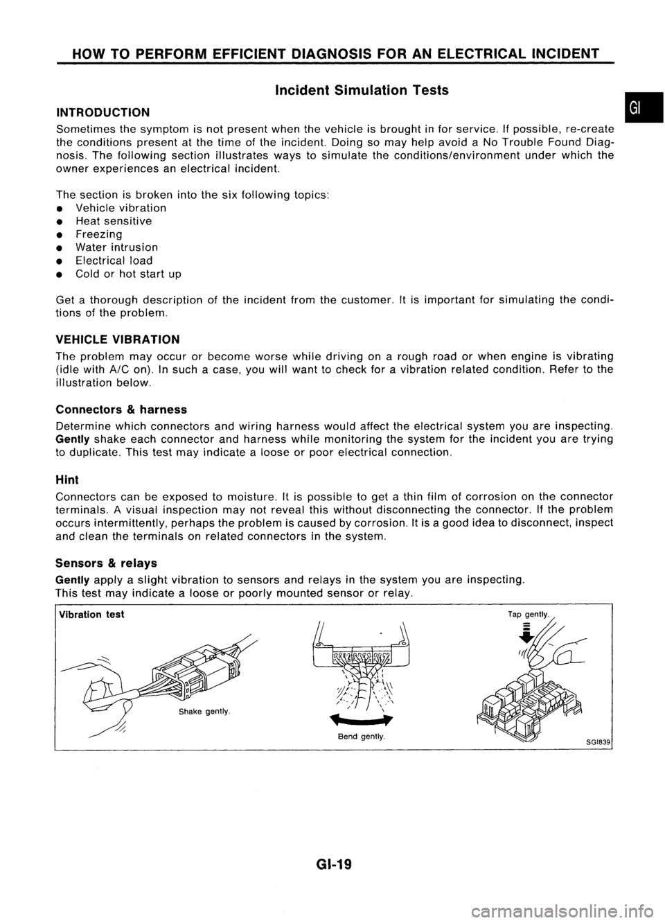
VEHICLE VIBRATION
The problem mayoccur orbecome worsewhiledriving onarough roadorwhen engine isvibrating
(idle with
AIC
on). Insuch acase, youwillwant tocheck foravibration relatedcondition. Refertothe
illustration below.
Connectors
&
harness
Determine whichconnectors andwiring harness wouldaffecttheelectrical systemyouareinspecting.
Gently
shakeeachconnector andharness whilemonitoring thesystem forthe incident youaretrying
to duplicate. Thistestmay indicate aloose orpoor electrical connection.
Hint
Connectors canbeexposed tomoisture. Itis possible toget athin film ofcorrosion onthe connector
terminals. Avisual inspection maynotreveal thiswithout disconnecting theconnector. Ifthe problem
occurs intermittently, perhapstheproblem iscaused bycorrosion. Itis agood ideatodisconnect, inspect
and clean theterminals onrelated connectors inthe system.
Sensors
&
relays
Gently
applyaslight vibration tosensors andrelays inthe system youareinspecting.
This testmay indicate aloose orpoorly mounted sensororrelay.
•
Vibration test
Bendgently.
GI-19
Tap
gently.
8GI839
Page 1380 of 1701

HOWTOPERFORM EFFICIENT DIAGNOSIS FORANELECTRICAL INCIDENT
Circuit Inspection (Cont'd)
VOLTAGE DROPTESTS
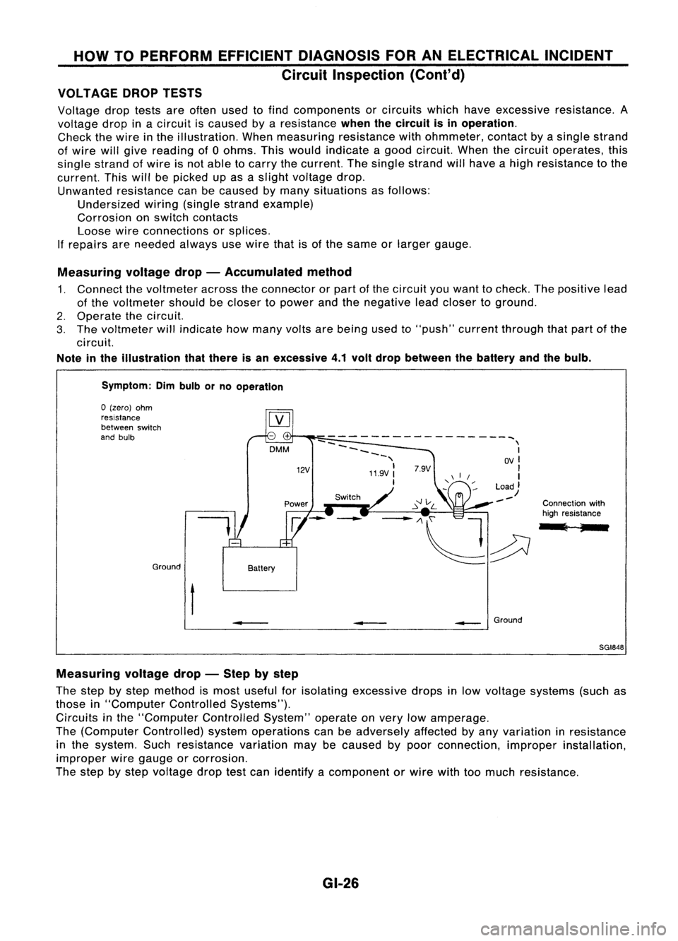
Voltage droptests areoften usedtofind components orcircuits whichhaveexcessive resistance. A
voltage dropinacircuit iscaused byaresistance
whenthecircuit isin operation.
Check thewire inthe illustration. Whenmeasuring resistancewithohmmeter, contactbyasingle strand
of wire willgive reading of0ohms. Thiswould indicate agood circuit. Whenthecircuit operates, this
single strand ofwire isnot able tocarry thecurrent. Thesingle strand willhave ahigh resistance tothe
current. Thiswillbepicked upasaslight voltage drop.
Unwanted resistance canbecaused bymany situations asfollows:
Undersized wiring(single strandexample)
Corrosion onswitch contacts
Loose wireconnections orsplices.
If
repairs areneeded alwaysusewire thatisof the same orlarger gauge.
Measuring voltagedrop-Accumulated method
1. Connect thevoltmeter acrosstheconnector orpart ofthe circuit youwant tocheck. Thepositive lead
of the voltmeter shouldbecloser topower andthenegative leadcloser toground.
2. Operate thecircuit.
3. The voltmeter willindicate howmany voltsarebeing usedto"push" current through thatpart ofthe
circuit.
Note inthe illustration thatthere isan excessive 4.1volt drop between thebattery andthebulb.
Symptom: Dimbulb orno operation
Switch Connectionwith
high resistance
l ;
--
------------------~
--
\
~~~~ I
-, OVI
11.9V:
'I
I
Load)
--
12V
DMM
Battery
Ground
o
(zero) ohm
resistance
between switch
and bulb
t
•
__
Ground
SGI848
Measuring voltagedrop-Step bystep
The step bystep method ismost useful forisolating excessive dropsinlow voltage systems (suchas
those in"Computer ControlledSystems").
Circuits inthe "Computer ControlledSystem"operateonvery lowamperage.
The (Computer Controlled) systemoperations canbeadversely affectedbyany variation inresistance
in the system. Suchresistance variationmaybecaused bypoor connection, improperinstallation,
improper wiregauge orcorrosion.
The step bystep voltage droptestcan identify acomponent orwire withtoomuch resistance.
GI-26