1995 NISSAN ALMERA N15 coolant level
[x] Cancel search: coolant levelPage 447 of 1701
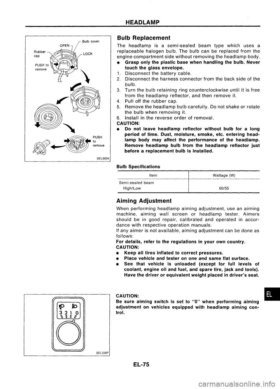
Bulbcover
SEL995K HEADLAMP
Bulb Replacement
The headlamp isasemi-sealed beamtypewhich usesa
replaceable halogenbulb.Thebulb canbereplaced fromthe
engine compartment sidewithout removing theheadlamp body.
• Grasp onlytheplastic basewhen handling thebulb. Never
touch theglass envelope.
1. Disconnect thebattery cable.
2. Disconnect theharness connector fromtheback sideofthe
bulb.
3. Turn thebulb retaining ringcounterclockwise until
it
is free
from theheadlamp reflector,andthen remove it.
4. Pull offthe rubber cap.
5. Remove theheadlamp bulbcarefully. Donot shake orrotate
the bulb when removing it.
6. Install inthe reverse orderofremoval.
CAUTION:
• Do not leave headlamp reflector withoutbulbforalong
period oftime. Dust,moisture, smoke,etc.entering head-
lamp bodymayaffect theperformance ofthe head lamp.
Remove headlamp bulbfrom thehead lamp reflector just
before areplacement bulbisinstalled.
Bulb Specifications
Item
Semi-sealed beam
High/Low Wattage
(W)
60/55
f>
to
3 21 0
~ nOD
o
SEL226PAiming
Adjustment
When performing headlamp aiming adjustment, useanaiming
machine, aimingwallscreen orheadlamp tester.Aimers
should beingood repair, calibrated andoperated inaccor-
dance withrespective operationmanuals.
If any aimer isnot available, aimingadjustment canbedone as
follows:
For details, refertothe regulations inyour owncountry.
CAUTION:
• Keep alltires inflated tocorrect pressures.
• Place vehicle andtester onone and same flatsurface.
• See thatvehicle isunloaded (exceptforfull levels of
coolant, engineoiland fuel, andspare tire,jack andtools).
Have thedriver orequivalent weightplaced indriver's seat.
CAUTION: •
Be sure aiming switchisset to
"0"
when performing aiming
adjustment onvehicles equipped withheadlamp aiming con-
trol.
EL-75
Page 473 of 1701
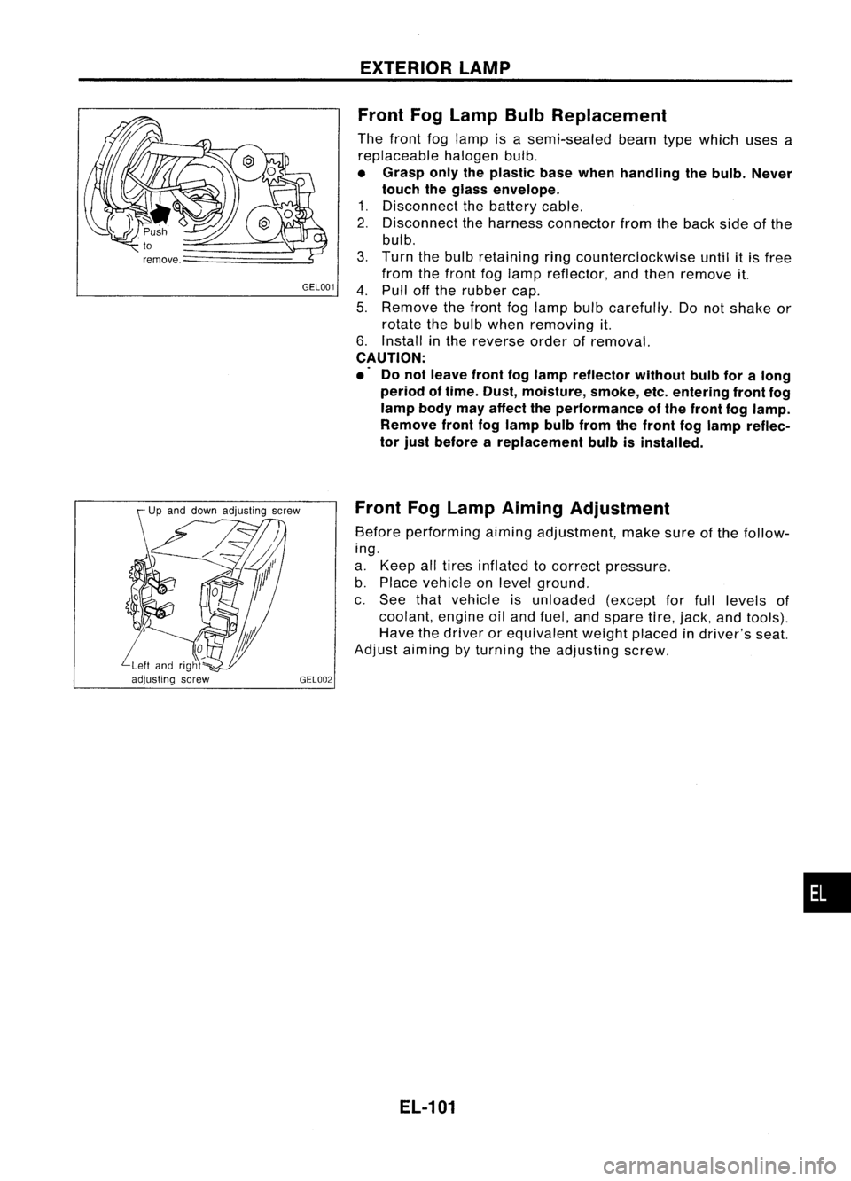
GEL001EXTERIOR
LAMP
Front FogLamp BulbReplacement
The front foglamp isasemi-sealed beamtypewhich usesa
replaceable halogenbulb.
• Grasp onlytheplastic basewhen handling thebulb. Never
touch theglass envelope.
1. Disconnect thebattery cable.
2. Disconnect theharness connector fromtheback sideofthe
bulb.
3. Turn thebulb retaining ringcounterclockwise untilitis free
from thefront foglamp reflector, andthen remove it.
4. Pull offthe rubber cap.
5. Remove thefront foglamp bulbcarefully. Donot shake or
rotate thebulb when removing it.
6. Install inthe reverse orderofremoval.
CAUTION:
.' Donot leave frontfoglamp reflector withoutbulbforalong
period oftime. Dust, moisture, smoke,etc.entering frontfog
lamp bodymayaffect theperformance ofthe front foglamp.
Remove frontfoglamp bulbfrom thefront foglamp reflec-
tor just before areplacement bulbisinstalled.
Front FogLamp Aiming Adjustment
Before performing aimingadjustment, makesureofthe follow-
ing.
a. Keep alltires inflated tocorrect pressure.
b. Place vehicle onlevel ground.
c. See thatvehicle isunloaded (exceptforfull levels of
coolant, engineoiland fuel, andspare tire,jack, andtools).
Have thedriver orequivalent weightplaced indriver's seat.
Adjust aiming byturning theadjusting screw.
EL-101
•
Page 754 of 1701

BASICSERVICE PROCEDURE
Idle Speedllgnition TiminglldleMixtureRatio
Adjustment
PREPARATION
• Make surethatthefollowing partsarein
good order.
(1) Battery
(2) Ignition system
(3) Engine oiland coolant levels
(4) Fuses
(5) ECM harness connector
(6) Vacuum hoses
(7) Airintake system
(Oil filler cap,oillevel gauge, etc.)
(8) Fuel pressure
(9)' Engine compression
(10) Throttle valve
(11) EGR valve operation -For Europe and
Israel andAustralia, andGA15DE M/Tmod-
els
Overall inspection sequence
INSPECTION
(12)
Evaporative emissionsystem
• On models equipped withairconditioner,
checks shouldbecarried outwhile theair
conditioner is"OFF".
• On models equipped withautomatic
transaxle, whenchecking idlespeed, ignition
timing andmixture ratio,checks shouldbe
carried outwhile shiftlever isin
"N"
position.
• When measuring
"CO"
percentage, insert
probe morethan40cm (15.7 in)into tailpipe .•
• Turn offheadlamps, heaterblower, rear
defogger.
• Keep frontwheels pointed straight ahead.
• Make thecheck afterthecooling fanhas
stopped.
Perform diagnostic testmode
1/
(Self-diagnostic results).
Check
&
adjust ignition timing.
Check
&
adjust idlespeed. NG
Repair orreplace.
Check oxygen sensor*1 function.
OK
Check
oxygen sensor*1 har-
ness.
Check CO%.
NG
NG
Repair orreplace harness.
OK Replace oxygensensor*1.
INSPECTION END Check
emission controlparts NGCheck oxygen sensor*1 function. OK
and repair orreplace ifneces-
sary.
*1: Heated oxygen sensor(ForEurope andIsrael, andAustralia AfTmodels)
Oxygen sensor(Except forEurope andIsrael, andAustralia AfTmodels)
EC-35
Page 792 of 1701
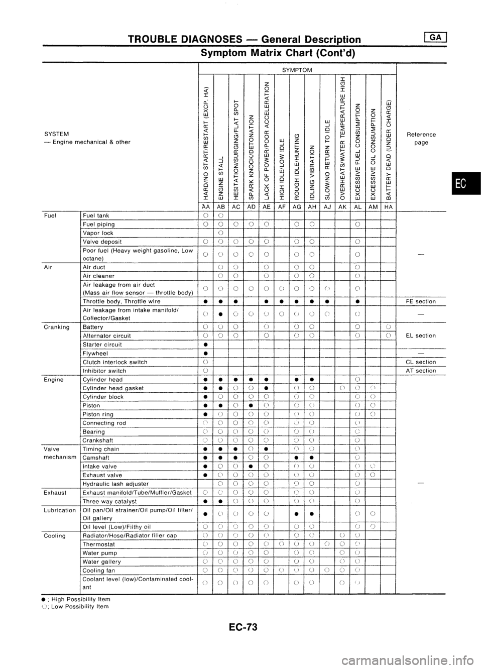
TROUBLEDIAGNOSES -General Description
Symptom MatrixChart(Cont'd)
SYMPTOM
J:
Z
CJ
~
0
I
J:
i=
LU
cL
I-
«
a:
a: ::J
UJ
0
0
LU
I-
Z
CJ
><
D..
-'
«
0
z
a:
~
LU
i=
0
z
0
a:
«
I-
0
0
LULU
D..
i=
J:
I-
«
-'
D..
:2
D..
0
0:
-'
i=
«
9
:2
::J
:2
SYSTEM
«
LL
«
0:
LU
C/J
a:
I-
0
Z
0
CJ
0
I-
Z
::J
LU
Reference
C/J
0
C/J
0
- Engine mechanical
&
other
z
0
LU
Z
I-
0
LU
I-
-'
0:
Z
Z
page
0:
(3
LU
D..
9
i=
z
Z
LU
0
0
2-
;:::
a:
0
a:
z
0
a:
I-
-'
0
0:
::J
~
LU
5:
::J
i=
::J
«
LU
-'
0
-'
J:
5:
«
-'
C/J
0
5:
0
«
I-
::J
(5
«
I-
Z
W
LU
en
LL
LU
C/J
«
00
-'
-'
a:
a:
0
I-
0
Z
D..
W
CD
I-
LU
LU
0
C/J
i=
~
LL
-'
9
:>
0
«
>
~
>-
z
0
Z
LU
(ij
C/J
a:
LU
«
~
9
J:
J:
0
Z
CJ
~
C/J
C/J
LU
I-
0:
~
CJ
Z
a:
LU LU
I-
(3
(jj
J:
a:
«
0
CJ
::J
:J
0
LU
0 0
I-
«
z
LU
D..
«
0
-'
>
><><
«
J:
LU
J:
C/J
-'
J:
a:
9
C/J
0
LU LU
CD
AA ASAC AD
AEAF
AG AH AJAK ALAM HA
Fuel Fueltank
0
U
Fuel piping
00 0
()
0 00 0
Vapor lock
U
Valve deposit
00 000 00
0
Poor fuel(Heavy weightgasoline, Low
0
C)
0 0
()
00
0
-
octane)
Air Airduct
00 0
00
0
Air cleaner
00
0
0
0
0
Air leakage fromairduct
()
(J
()
()
0
0
0 0
("
)
C'
(Mass airflow sensor -throttle body)
Throttle body,Throttle wire
••• •
••
•• •
FE
section
Air leakage fromintake manifold/
0
•
(~)
0
tJ
0
U
C;
U
-
Collector/Gasket
Cranking Battery
0
U
()
(J
00 0
':J
Alternator circuit
()
0
0
0
(J
0 0
(J
ELsection
Starter circuit
•
Flywheel
•
-
Clutch interlock switch
0
CL
section
Inhibitor switch
()
ATsection
Engine Cylinderhead
••
• •
• •
•
()
Cylinder headgasket
••
0
0
•
U
()
0
()
C'
Cylinder block
•
0
0 0
0
()
(J
0
0
Piston
••
0
•
(J
()
()
()
0
Piston ring
•
U
00
0
U
()
U
()
Connecting rod
('
0
0
00
)
U
(
)
Bearing
(i
0
()
0
()
U
0
C
Crankshaft
Cl
(~)
0 0
()
()
0
0
Valve Timingchain
•••
CJ
•
n
()
('
mechanism Camshaft
•••
0
0
•
•
0
Intake valve
•
0
0
•
0
()
':J
0
l~'
Exhaust valve
•
C)
0
()
()
U
u
()
0
HydraUlic lashadjuster
00
0
0
()
()
0
-
Exhaust Exhaust
manifoldlTube/Muffler/Gasket
C)
c:
()
()
0
U
()
U
Three waycatalyst
••
0
U
0 0
()
0
Lubrication Oil
pan/Oil strainer/Oil pump/Oilfilter/
•
Ci
0 0
0
•
•
()
0
Oil gallery
Oil level (Low)/Filthy oil
()
0
()
()()
(J
0
U
()
Cooling Radiator/Hose/Radiator
fillercap
()
0 0
()
()
C)
U
U
()
Thermostat
00
0
0
C)
0
()
00
0
Cl
Water pump
u
0
U
0
0
()
Ci
C)
U
Water gallery
U
()
0
()
0 0
U
0
U
Cooling fan
0
()
CJ
U
0
U
I)
U
()
CJ
(i
Coolant level(low)/Contaminated cool-
U
0
0 0
0
00
()
)
ant
• ;High Possibility Item
U;
Low Possibility Item
EC-73
•
Page 869 of 1701
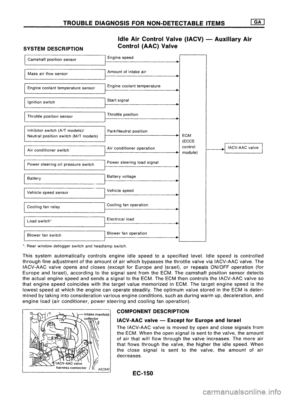
TROUBLEDIAGNOSIS FORNON-DETECTABLE ITEMS
SYSTEM DESCRIPTION Idle
AirControl Valve(IACV) -Auxiliary Air
Control (AAC)Valve
Camshaft positionsensor Engine
speed
I
Mass
airflow sensor Amount
ofintake air
I
Engine coolant temperature sensor Engine
coolant temperature
~
I
Ignition switch Start
signal
I
Throttle positionsensor Throttle
position
~
I
Inhibitor switch(A/Tmodels)/
Park/Neutralposition
Neutral position switch(M/Tmodels) ECM
(ECCS
Air conditioner operation control
!
IACV-AAC valve
I
Air conditioner switch
module)
Power steering oilpressure switch Power
steering loadsignal
I
Battery
~
Battery voltage
Vehicle speedsensor Vehicle
speed
Cooling fanrelay Cooling
fanoperation
Load switch' Electrical
load
Blower fanswitch Blower
fanoperation
': Rear window defogger switchandheadlamp switch.
This system automatically controlsengineidlespeed toaspecified level.Idlespeed iscontrolled
through fineadjustment ofthe amount ofair which bypasses thethrottle valveviaIACV-AAC valve.The
IACV-AAC valveopens andcloses (except forEurope andIsrael), orrepeats ON/OFF operation (for
Europe andIsrael), according tothe signal sentfrom theECM. Thecamshaft positionsensordetects
the actual engine speedandsends asignal tothe ECM. TheECM thencontrols theIACV-AAC valveso
that engine speedcoincides withthetarget valuememorized inECM. Thetarget engine speedisthe
lowest speedatwhich theengine canoperate steadily. Theoptimum valuestored inthe ECM isdeter-
mined bytaking intoconsideration variousengineconditions, suchasduring warmup,deceleration, and
engine load(airconditioner, powersteering andcooling fanoperation).
COMPONENT DESCRIPTION
IACV-AAC valve-Except forEurope andIsrael
The IACV-AAC valveismoved byopen andclose signals from
the ECM. When theopen signal issent tothe valve, theamount
of air that willflow through thevalve increases. Themore air
that flows through thevalve, thehigher theidle speed. When
the close signal issent tothe valve. theamount ofair
decreases.
EC-150
Page 962 of 1701

BASICSERVICE PROCEDURE
Idle Speedllgnition TiminglldleMixtureRatio
Adjustment
PREPARATION
• Make surethatthefollowing partsarein
good order.
(1) Battery
(2) Ignition system
(3) Engine oiland coolant levels
(4) Fuses
(5) ECM harness connector
(6) Vacuum hoses
(7) Airintake system
(Oil filler cap,oillevel gauge, etc.)
(8) Fuel pressure
(9) Engine compression
(10) Throttle valve
Overall inspection sequence
INSPECTION
•
•
•
•
•
•
On
models equipped withairconditioner,
checks shouldbecarried outwhile theair
conditioner is"OFF".
On models equipped withautomatic
transaxle, whenchecking idlespeed, ignition
timing andmixture ratio,checks shouldbe
carried outwhile shiftlever isin "N" position.
When measuring "CO"percentage, insert
probe morethan40cm (15.7 in)into tailpipe.
Turn offheadlamps, heaterblower, rear
defogger. Keep frontwheels pointed straight ahead.
Make thecheck afterthecooling fanhas
stopped.
•
Perform diagnostic testmode II
(Self-diagnostic results).
OK
Check
&
adjust ignition timing.
Check
&
adjust idlespeed.
Check heated oxygen sensor
function. NG
Repair orreplace.
NG Check heated oxygen sensor
harness. NG
Repair orreplace harness.
OK OK
Check CO%. OKReplace heatedoxygen sensor.
NG
INSPECTION END Check
emission controlparts
and repair orreplace ifneces-
sary.
EC-243
NG
Check heated oxygen sensor
function.
OK
Page 995 of 1701
TROUBLEDIAGNOSIS -General Descrip_tio_n
1s_R_1
Symptom MatrixChart(Cont'd)
SYMPTOM
z
0
i=
«
W
a:
z
w
w
w
CJ
CJ
....J
....J
0
Z
a:
w
i=
0
a:
(.)
9
8
«
0.. i=
:I:
::J
(.)
z
:2
i='
en
«
:I:
8
:J
0..
(.)
Q
0
f:::.
CJ
:J
:2
a:
a:
:E
z
w
en
SYSTEM
....J
~
0
0
en
z
:J
w
Reference
0
0..
W
a
w
en
Cl
- Engine mechanical
&
other
I-
en
0
z
0
z
z
S:?-
a: 0..
....J
e-
(.)
0
page
I-
«
l-
ii.
9
~
....J
(.)
2-
a:
~
«
w
0
z
w
CJ
Cl
....J ....J
:.:::
0
:J
....J
Z
«
....J
u.
~
I-
(.)
u..
0
a
«
I-
w
«
Z
0
z
enen
w
en
a:
....J
I-
0..
Z
0
WW
:J
W
W
I-
....J
a:
Cl
0 0
9
en
0
a:
z
a:a:
a:
> >
«
0
«
>-
i=
u..
:J
:.:::
ii:
enen
0
:I:
Z Z
W
0
l-
ii:
w w
a:
Ci Ci
:I:
Z
«
w
:.:::
a:
z
en
en
:I:
(.)
(.)
w
CJ
a
I-
:.:::
a:a:
:.:::
w
a
w
w
a:
a:a:
~
a:
a:
:J
en
(.)
«
(.)
I-
(.)
(.)
w
w
w
« «
0
z
w
«
0
0..
«
u..
Z
x x
>>>
«
:I: :I:
a:
w
:I:
....J
Z
en
(l)
«
w w
w
00 0
(l)
1A 1B
1C 1F1H
1R 1S
1M 1J1L1K
1T
1V
1N
1P1X 1Y
Fuel Fueltank
00 0
Fuel piping
00 0000 000
0
Vapor lock
00
Valve deposit
000 000 00 0
Poor fuel(Heavy weightgasoline. Low
0000 00 00
0
-
octane)
Air Airduct
00 00 0
Air cleaner
0
0
00 0
Air leakage fromairduct
00 00 00 0
0 0
0
(Mass airflow sensor -throttle body)
Throttle body.Throttle wire
•
•
•
•
• •
•
FE
section
Air leakage fromintake
manifoldl
00 0
•
0
0 0
00 0
-
Coliector/Gasket
Cranking Battery
0
0
00 0
0 0
0
0
Alternator circuit
00
00
0
0 0
00
EL
section
Starter circuit
••
Flywheel
•
0
-
Inhibitor switch
00
ATsection
Engine Cylinderhead
•
0
•
•
••
•
0
0
Cylinder headgasket
•
0
()
•
0
•
0
0
00
Cylinder block
•
0
()
0 00 0 00
Piston
•
0
0
•
0
0
•
0
0
Piston ring
•
0
00 0
0 0 00
Connecting rod
00 00
00 0 0
Bearing
000 000 0
0
Crankshaft
00
0 0
0
0 0
0
Valve Timingchain
•
0
0
••
•
0
0 0
mechanism Camshaft
•
0
•• •
0
0 0
Intake valve
•
0
00 0
0
•
0
0
0
Exhaust valve
•
0
00 00 0000
Hydraulic lashadjuster
0000
'0
0 0
-
Exhaust Exhaust
manifoldlTube/Mulfler/Gasket
00
00 0
0
00
0 0
Three waycatalyst
•
0
0
•
0
0 000 0
Lubrication Oilpan/Oil strainer/Oil pump/Oilfilterl
000
0
0 0
0
Oil gallery
••
Oil level (Low)/Filthy oil
00 0000
0 0
0
Cooling Radiator/Hose/Radiator fillercap
00
0 00
0 0 00
Thermostat
00
00 0
0 00 0
00
Water pump
000 000 0 0
0
Water gallery
00 00 00
0 0
0
Cooling fan
00 0
00
0 0
0 0
0
0
Coolant level(low)/Contaminated cool-
00
0000
0 0
0
ant
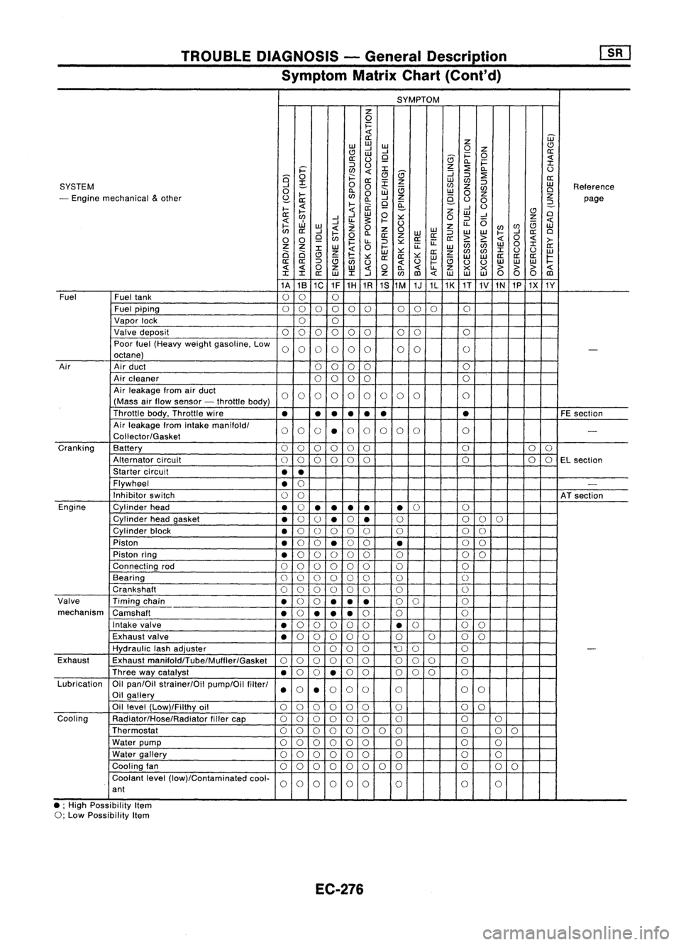
• ;High Possibility Item
0; Low Possibility Item
EC-276
Page 1054 of 1701
TROUBLEDIAGNOSIS FORNON-DETECTABLE ITEMS
SYSTEM DESCRIPTION Idle
AirControl Valve(IACV) -Auxiliary Air
Control (AAC)Valve
Camshaft positionsensor Engine
speed
~
I
Amount ofintake air
Mass airflow sensor
I
Engine coolant temperature sensor Engine
coolant temperature
I
Ignition switch Start
signal
I
Throttle position sensor Throttle
"position
I
ECM
Inhibitor switch(A/Tmodels)/ Park/Neutral
position (ECCS
control
!
IACV-AAC valve
I
Neutral position switch(M/Tmodels)
module)
Air conditioner switch Air
conditioner operation
Power steering oilpressure switch Power
steering loadsignal
I
Battery Battery
voltage
Vehicle speedsensor Vehicle
speed
I
l
Cooling fan Cooling
fanoperation
I
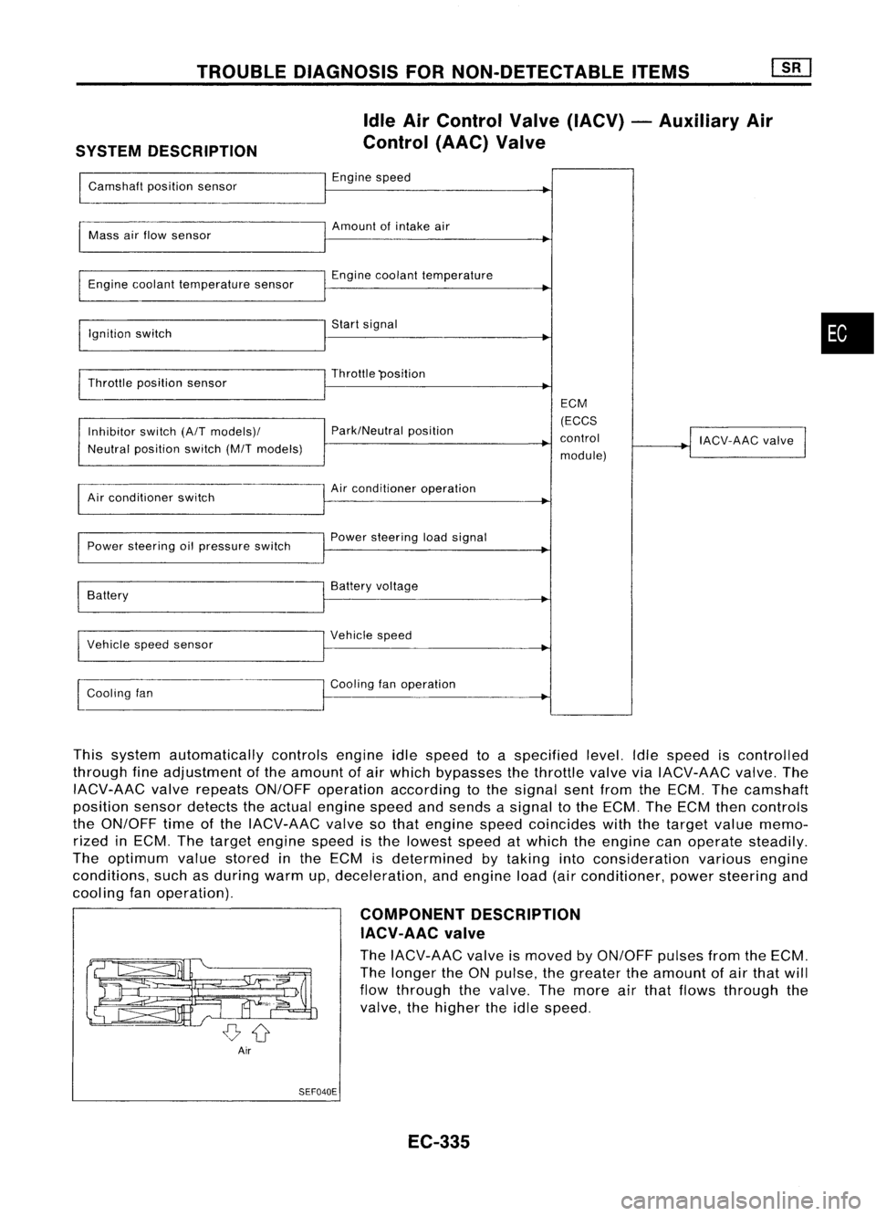
This system automatically controlsengineidlespeed toaspecified level.Idlespeed iscontrolled
through fineadjustment ofthe amount ofair which bypasses thethrottle valveviaIACV-AAC valve.The
IACV-AAC valverepeats ON/OFF operation according tothe signal sentfrom theECM. Thecamshaft
position sensordetects theactual engine speedandsends asignal tothe ECM. TheECM thencontrols
the ON/OFF timeofthe IACV-AAC valvesothat engine speedcoincides withthetarget valuememo-
rized inECM. Thetarget engine speedisthe lowest speedatwhich theengine canoperate steadily.
The optimum valuestored inthe ECM isdetermined bytaking intoconsideration variousengine
conditions, suchasduring warmup,deceleration, andengine load(airconditioner, powersteering and
cooling fanoperation).
COMPONENTDESCRIPTION
IACV-AAC valve
The IACV-AAC valveismoved byON/OFF pulsesfromtheECM.
The longer theONpulse, thegreater theamount ofair that will
flow through thevalve. Themore airthat flows through the
valve, thehigher theidle speed.
Air SEF040E
EC-335
•