1995 NISSAN ALMERA N15 weight
[x] Cancel search: weightPage 7 of 1701

PREPARATIONANDPRECAUTIONS
Service Notice
Supplemental RestraintSystem(SRS)"AIR
BAG" (DualAirBag System)
The Supplemental RestraintSystem"AirBag" usedalong withaseat belt, helps toreduce therisk or
severity ofinjury tothe driver andfront passenger inafrontal collision. TheSupplemental Restraint
System consists ofair bag modules (locatedinthe center ofthe steering wheelandonthe instrument
panel onthe passenger side),adiagnosis sensorunit,warning lamp,wiring harness andspiral cable.
Information necessarytoservice thesystem safelyisincluded inthe
RSsection
ofthis Service Manual.
WARNING:
• Toavoid rendering theSRS inoperative, whichcouldincrease therisk ofpersonal injuryordeath
in the event ofacollision whichwould resultinair bag inflation, allmaintenance mustbeperformed
by an authorized NISSANdealer.
• Improper maintenance, includingincorrectremovalandinstallation ofthe SRS, canlead topersonal
injury caused byunintentional activationofthe system.
Ii
Donot use electrical testequipment onany circuit related tothe SRS unless instructed tointhis
Service Manual. SRSwiring harnesses arecovered withyellow insulation eitherjustbefore the
harness connectors orfor the complete harness,foreasy identification.
•
Before proceeding withdisassembly, thor-
oughly cleantheoutside ofthe transaxle. Itis
important toprevent theinternal partsfrom
becoming contaminated bydirt orother for-
eign matter.
• Disassembly shouldbedone inaclean work
area.
• Use lint-free clothortowels forwiping parts
clean. Common shopragscanleave fibers
that could interfere withtheoperation ofthe
transaxle.
• Place disassembled partsinorder, onaparts
rack, foreasier andproper assembly.
• Allparts should becarefully cleaned-witha
general purpose, non-flammable solvent
before inspection orreassembly.
• Gaskets, sealsandO-rings shouldbe
replaced anytime thetransaxle isdisassem-
bled.
• Itis very important toperform functional tests
whenever theyareindicated. •
The valve bodycontains precision partsand
requires extremecarewhen partsare
removed andserviced. Placedisassembled
valve bodyparts inorder, onaparts rack,for
easier andproper assembly. Carewillalso
prevent springs andsmall partsfrombecom-
ing scattered orlost.
• Properly installedvales,sleeves, plugs,etc.
will slide along theirbores inthe valve body
under theirownweight.
• Before assembly, applyacoat ofrecom-
mended ATFtoall parts. Apply petroleum
jelly toprotect O-ringandseals, orhold bear-
ings andwashers inplace during assembly.
Do not use grease.
• Extremely careshould betaken toavoid dam-
age toO-rings, sealsandgaskets when
assembling.
• After overhaul, refillthetransaxle withnew
ATF.
•
Supplemental RestraintSystem(SRS)"AIR
BAG" (Single AirBag System)
The Supplemental RestraintSystem"AirBag" andused along withaseat belt,helps toreduce therisk
or severity ofinjury tothe driver inafrontal collision. TheSupplemental RestraintSystemconsists of
an air bag module (located inthe center ofthe steering wheel),adiagnosis sensorunit,warning lamp,
wiring harness andspiral cable. Information necessarytoservice thesystem safelyisincluded inthe
RS section
ofthis Service Manual.
WARNING:
• Toavoid rendering theSRS inoperative, whichcouldincrease therisk ofpersonal injuryordeath
in the event ofacollision whichwould resultinair bag inflation, allmaintenance mustbeperformed
by an authorized NISSANdealer.
• Improper maintenance, includingincorrectremovalandinstallation ofthe SRS, canlead topersonal
injury caused byunintentional activationofthe system.
• Donot use electrical testequipment onany circuit related tothe SRS unless instructed tointhis
Service Manual.
AT-7
Page 65 of 1701
SAT070D
\LOW secondary weight
Low primary weight
Governor valve
High primary weight
High secondary weight
SAT071DDISASSEMBL
Y
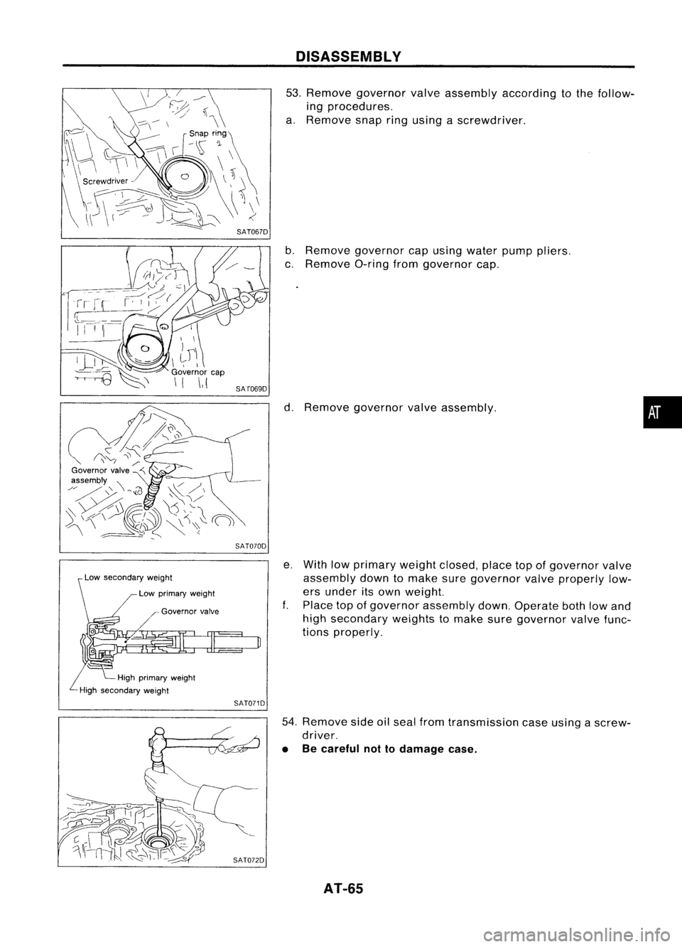
53. Remove governor valveassembly according tothe follow-
ing procedures.
a. Remove snapringusing ascrewdriver.
b. Remove governor capusing water pumppliers.
c. Remove a-ringfromgovernor cap.
d. Remove governor valveassembly.
e. With lowprimary weightclosed, placetopofgovernor valve
assembly downtomake suregovernor valveproperly low-
ers under itsown weight.
f. Place topofgovernor assembly down.Operate bothlowand
high secondary weightstomake suregovernor valvefunc-
tions properly.
54. Remove sideoilseal from transmission caseusing ascrew-
driver.
• Becareful nottodamage case.
AT-55
•
Page 177 of 1701
REPLACEMENTOPERATIONS
Rear Floor Rear ________
GENERALINFORMATION _
Identification Number(Cont'd)
(Work afterrearpanel havebeen removed.)
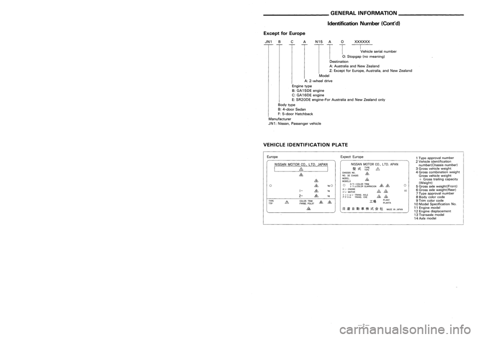
ExceptforEurope
IN 1 .B CAN 15A
0
XXXXXX
T
T
--c:::
serialnumber
0:
Stopgap (nomeaning)
Destination
A: Australia andNew Zealand
Z: Except forEurope, Australia, andNew Zealand
Model
A: 2-wheel drive
Engine type
B: GA 15DE engine
C: GA 16DE engine
E: SR20DE engine-For AustraliaandNew Zealand only
Body type
B: 4-door Sedan
F: 5-door Hatchback
Manufacturer
IN 1:Nissan, Passenger vehicle
VEHICLE IDENTIFICATION PLATE
1Type approval number
2 Vehicle identification
number(Chassis number)
3 Gross vehicle weight
4 Gross combination weight
Gross vehicle weight
+
Gross trailing capacity
(Weight)
5 Gross axleweight(Front)
6 Gross axleweight(Rear)
7 Type approval number
8 Body colorcode
9 Trim color code
10 Model Specification No.
11 Engine model
12 Engine displacement
13 Transaxle model
14 Axle model
cc
o
PLANT
PlANTA
El
ii:
13IJJ
if[
**
it~
*1
MADEINJAPAN
NISSAN
MOTORCO.,LTD. APAN
~ tt
~(:l
&
~~~sg~
CNHOA"SIS ~
~~~~~o
&
o ~
0
:ggtg~
~~~RNICION ~
&.
~~ ~~~~~ &
£
; ;~)~ /~~~~~'. AE~~
A1L11
Expect
Europe
~
&
kgO
1-
&
kg
2-
&
kg
COlOR. TRIM
~
&
FARBE. POlST
&
NISSAN
MOTORCO.,LTD. JAPAN
I ~ I
~
o
TYPE
TTP
Europe
FR
_2
3D
HI
B:3door hatchback
5D
HI
B:5door hatchback
Service
Joint
111
~
2-spot welds 3-spotwelds M.
I.
G plug weld .MIG seam weld/
(For 3panels plugweld method )P:
F
weld
• rr=- •
A
===-=
.'S~
.L.LLL
GTJ --- ~
-43-
-2-
Page 192 of 1701
__________ BODYALIGNMENT ___________
PRECAUTIONS _
Underbody Precautions
ForHandling HighStrength Steel
• InNissan vehicles, HSSplates of373 N/mm
2
(38kg/mm
2,
54klb/sq in)(NP130) aremost commonly
utilized, andthose withatensile strength of785 to981 N/mm
2
(80to100 kg/mm
2,
114to142 klb/sq
in) (NP150) areused onlyonparts requiring muchmorestrength.
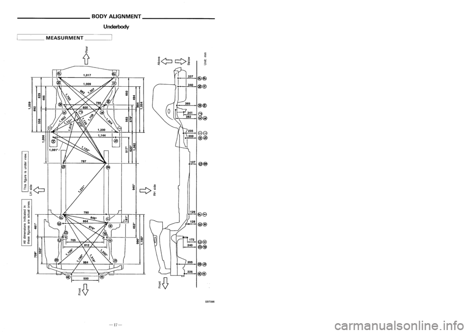
HIGH
STRENGTH STEEL(HSS)USED INNISSAN VEHICLES
High
strength steelhasbeen usedforbody panels inorder toreduce vehicle weight.
Accordingly, precautionsinrepairing automotive bodiesmadeofhigh strength steelaredescribed below:
Tensile strength Nissan designation Major
applicable parts
• Side member
373N/mm
2
•
Hoodledge
(38 kg/mm
2,
54klb/sq in) NP130
•
Pillar
• Hood
.Trunk lidouter
785-981 N/mm
2
•Bumper reinforcement
(80-100 kg/mm
2
NP150
114-142 klb/sqin) •
Door guard beam
E
E
127
@>@)
235
~200
ee
@@
o
It)
CD
N
.. CD
.. 00
~ N~
It)
CD
CD
It)
C!.
~
CD
It)
It)
en
N
It)
CD CD
IIIlI:t'
(ij
Q)
er:
iJ
--------
en
It)
C!.
N
~ en
co
____
MEASURMENT _
..
o
.. It)
0)
It)
o
I'
..
.. 0
CD CD
en~
0) .,
~
129
@8
@@
@)@)
225
SBT096
-17- -28-
Page 203 of 1701
__________ BODYALIGNMENT ___________
PRECAUTIONS _
Underbody Precautions
ForHandling HighStrength Steel
• InNissan vehicles, HSSplates of373 N/mm
2
(38kg/mm
2,
54klb/sq in)(NP130) aremost commonly
utilized, andthose withatensile strength of785 to981 N/mm
2
(80to100 kg/mm
2,
114to142 klb/sq
in) (NP150) areused onlyonparts requiring muchmorestrength.
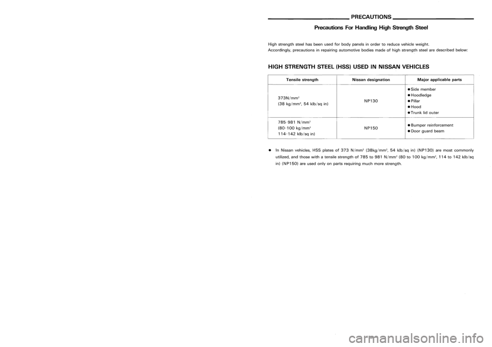
HIGH
STRENGTH STEEL(HSS)USED INNISSAN VEHICLES
High
strength steelhasbeen usedforbody panels inorder toreduce vehicle weight.
Accordingly, precautionsinrepairing automotive bodiesmadeofhigh strength steelaredescribed below:
Tensile strength Nissan designation Major
applicable parts
• Side member
373N/mm
2
•
Hoodledge
(38 kg/mm
2,
54klb/sq in) NP130
•
Pillar
• Hood
.Trunk lidouter
785-981 N/mm
2
•Bumper reinforcement
(80-100 kg/mm
2
NP150
114-142 klb/sqin) •
Door guard beam
E
E
127
@>@)
235
~200
ee
@@
o
It)
CD
N
.. CD
.. 00
~ N~
It)
CD
CD
It)
C!.
~
CD
It)
It)
en
N
It)
CD CD
IIIlI:t'
(ij
Q)
er:
iJ
--------
en
It)
C!.
N
~ en
co
____
MEASURMENT _
..
o
.. It)
0)
It)
o
I'
..
.. 0
CD CD
en~
0) .,
~
129
@8
@@
@)@)
225
SBT096
-17- -28-
Page 218 of 1701
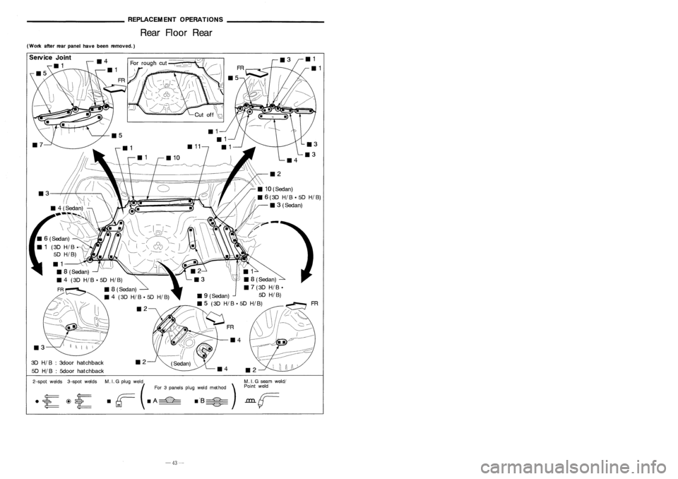
REPLACEMENTOPERATIONS
Rear Floor Rear ________
GENERALINFORMATION _
Identification Number(Cont'd)
(Work afterrearpanel havebeen removed.)
ExceptforEurope
IN 1 .B CAN 15A
0
XXXXXX
T
T
--c:::
serialnumber
0:
Stopgap (nomeaning)
Destination
A: Australia andNew Zealand
Z: Except forEurope, Australia, andNew Zealand
Model
A: 2-wheel drive
Engine type
B: GA 15DE engine
C: GA 16DE engine
E: SR20DE engine-For AustraliaandNew Zealand only
Body type
B: 4-door Sedan
F: 5-door Hatchback
Manufacturer
IN 1:Nissan, Passenger vehicle
VEHICLE IDENTIFICATION PLATE
1Type approval number
2 Vehicle identification
number(Chassis number)
3 Gross vehicle weight
4 Gross combination weight
Gross vehicle weight
+
Gross trailing capacity
(Weight)
5 Gross axleweight(Front)
6 Gross axleweight(Rear)
7 Type approval number
8 Body colorcode
9 Trim color code
10 Model Specification No.
11 Engine model
12 Engine displacement
13 Transaxle model
14 Axle model
cc
o
PLANT
PlANTA
El
ii:
13IJJ
if[
**
it~
*1
MADEINJAPAN
NISSAN
MOTORCO.,LTD. APAN
~ tt
~(:l
&
~~~sg~
CNHOA"SIS ~
~~~~~o
&
o ~
0
:ggtg~
~~~RNICION ~
&.
~~ ~~~~~ &
£
; ;~)~ /~~~~~'. AE~~
A1L11
Expect
Europe
~
&
kgO
1-
&
kg
2-
&
kg
COlOR. TRIM
~
&
FARBE. POlST
&
NISSAN
MOTORCO.,LTD. JAPAN
I ~ I
~
o
TYPE
TTP
Europe
FR
_2
3D
HI
B:3door hatchback
5D
HI
B:5door hatchback
Service
Joint
111
~
2-spot welds 3-spotwelds M.
I.
G plug weld .MIG seam weld/
(For 3panels plugweld method )P:
F
weld
• rr=- •
A
===-=
.'S~
.L.LLL
GTJ --- ~
-43-
-2-
Page 447 of 1701
Bulbcover
SEL995K HEADLAMP
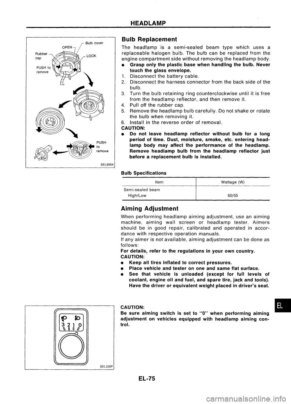
Bulb Replacement
The headlamp isasemi-sealed beamtypewhich usesa
replaceable halogenbulb.Thebulb canbereplaced fromthe
engine compartment sidewithout removing theheadlamp body.
• Grasp onlytheplastic basewhen handling thebulb. Never
touch theglass envelope.
1. Disconnect thebattery cable.
2. Disconnect theharness connector fromtheback sideofthe
bulb.
3. Turn thebulb retaining ringcounterclockwise until
it
is free
from theheadlamp reflector,andthen remove it.
4. Pull offthe rubber cap.
5. Remove theheadlamp bulbcarefully. Donot shake orrotate
the bulb when removing it.
6. Install inthe reverse orderofremoval.
CAUTION:
• Do not leave headlamp reflector withoutbulbforalong
period oftime. Dust,moisture, smoke,etc.entering head-
lamp bodymayaffect theperformance ofthe head lamp.
Remove headlamp bulbfrom thehead lamp reflector just
before areplacement bulbisinstalled.
Bulb Specifications
Item
Semi-sealed beam
High/Low Wattage
(W)
60/55
f>
to
3 21 0
~ nOD
o
SEL226PAiming
Adjustment
When performing headlamp aiming adjustment, useanaiming
machine, aimingwallscreen orheadlamp tester.Aimers
should beingood repair, calibrated andoperated inaccor-
dance withrespective operationmanuals.
If any aimer isnot available, aimingadjustment canbedone as
follows:
For details, refertothe regulations inyour owncountry.
CAUTION:
• Keep alltires inflated tocorrect pressures.
• Place vehicle andtester onone and same flatsurface.
• See thatvehicle isunloaded (exceptforfull levels of
coolant, engineoiland fuel, andspare tire,jack andtools).
Have thedriver orequivalent weightplaced indriver's seat.
CAUTION: •
Be sure aiming switchisset to
"0"
when performing aiming
adjustment onvehicles equipped withheadlamp aiming con-
trol.
EL-75
Page 473 of 1701
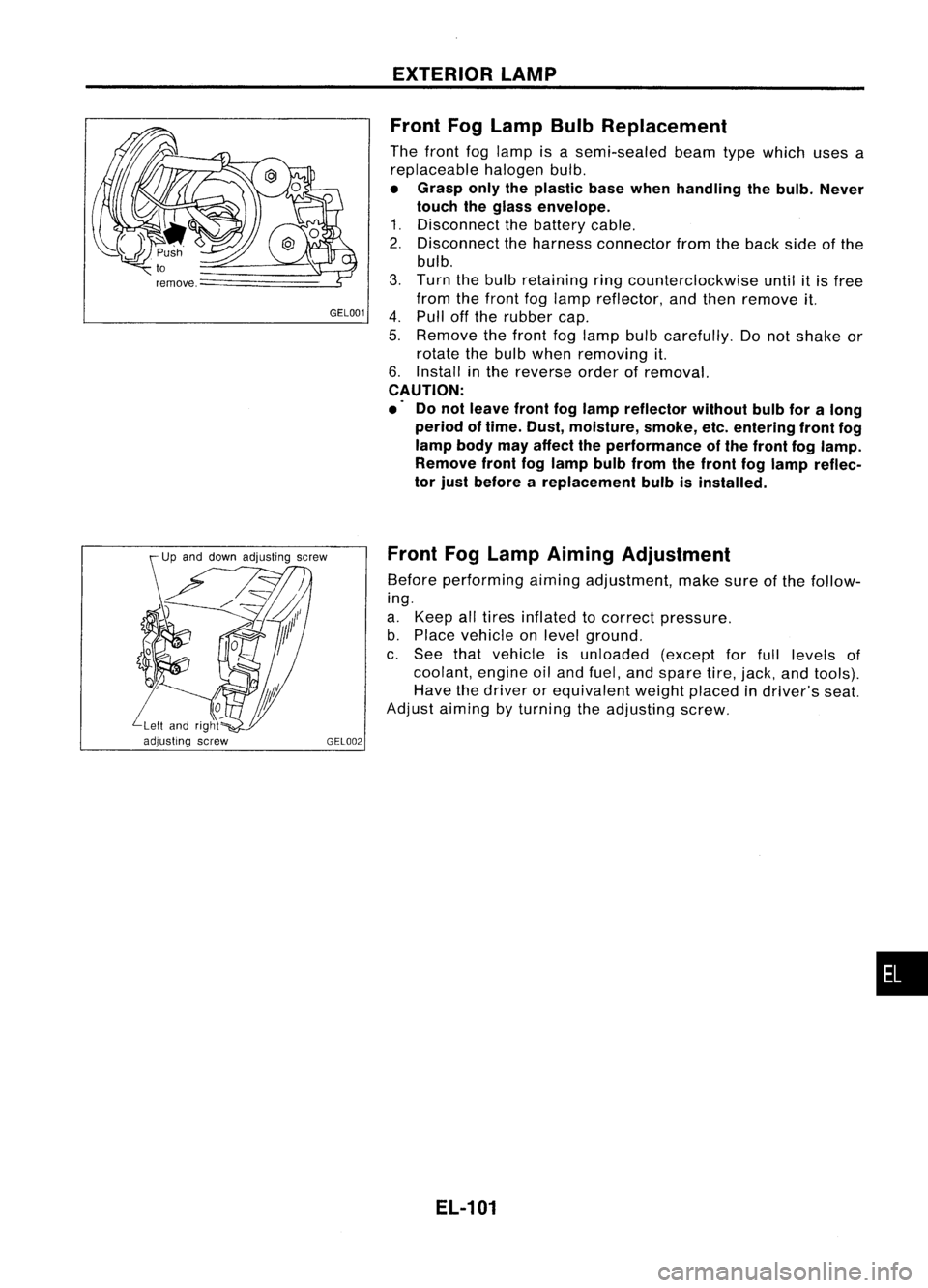
GEL001EXTERIOR
LAMP
Front FogLamp BulbReplacement
The front foglamp isasemi-sealed beamtypewhich usesa
replaceable halogenbulb.
• Grasp onlytheplastic basewhen handling thebulb. Never
touch theglass envelope.
1. Disconnect thebattery cable.
2. Disconnect theharness connector fromtheback sideofthe
bulb.
3. Turn thebulb retaining ringcounterclockwise untilitis free
from thefront foglamp reflector, andthen remove it.
4. Pull offthe rubber cap.
5. Remove thefront foglamp bulbcarefully. Donot shake or
rotate thebulb when removing it.
6. Install inthe reverse orderofremoval.
CAUTION:
.' Donot leave frontfoglamp reflector withoutbulbforalong
period oftime. Dust, moisture, smoke,etc.entering frontfog
lamp bodymayaffect theperformance ofthe front foglamp.
Remove frontfoglamp bulbfrom thefront foglamp reflec-
tor just before areplacement bulbisinstalled.
Front FogLamp Aiming Adjustment
Before performing aimingadjustment, makesureofthe follow-
ing.
a. Keep alltires inflated tocorrect pressure.
b. Place vehicle onlevel ground.
c. See thatvehicle isunloaded (exceptforfull levels of
coolant, engineoiland fuel, andspare tire,jack, andtools).
Have thedriver orequivalent weightplaced indriver's seat.
Adjust aiming byturning theadjusting screw.
EL-101
•