1995 NISSAN ALMERA N15 weight
[x] Cancel search: weightPage 709 of 1701
View
from
B FRONT
SUSPENSION
Stabilizer Bar(Cont'd)
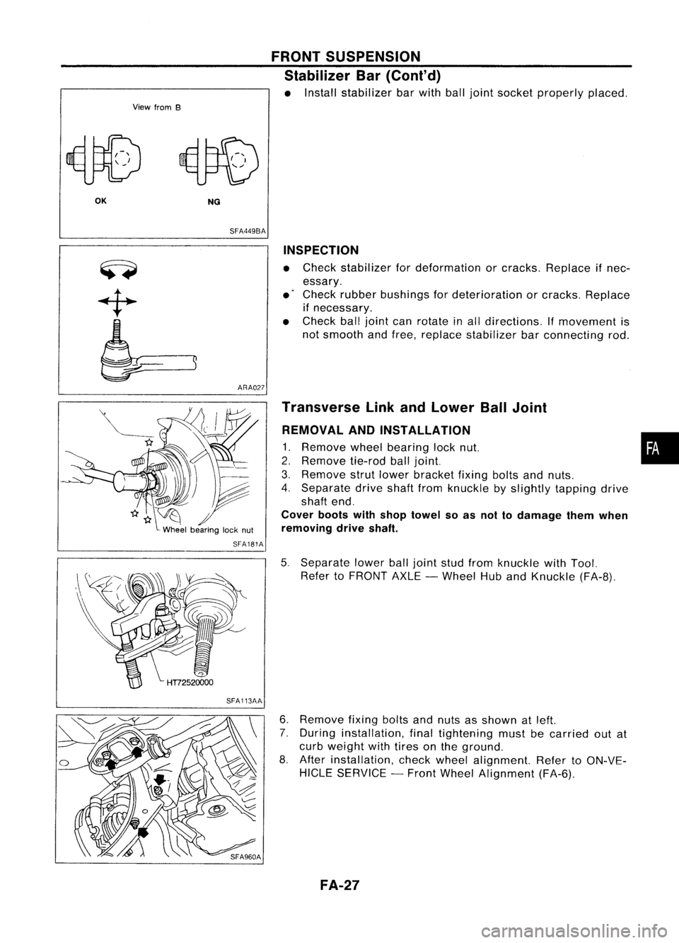
• Install stabilizer barwith balljoint socket properly placed.
OK NG
SFA449BA
ARA027 INSPECTION
• Check stabilizer fordeformation orcracks. Replace ifnec-
essary.
• Check rubber bushings fordeterioration orcracks. Replace
if necessary.
• Check balljoint canrotate inall directions. If
movement
is
not smooth andfree, replace stabilizer barconnecting rod.
SFA181A
SFA113AA Transverse
LinkandLower BallJoint
REMOVAL ANDINSTALLATION
1. Remove
wheelbearing locknut. •
2. Remove
tie-rodballjoint.
3. Remove
strutlower bracket fixingboltsandnuts.
4. Separate driveshaftfromknuckle byslightly tapping drive
shaft end.
Cover bootswithshop towel soas not todamage themwhen
removing driveshaft.
5. Separate lowerballjoint studfrom knuckle withTool.
Refer toFRONT AXLE-Wheel HubandKnuckle (FA-8).
6. Remove
fixingboltsandnuts asshown atleft.
7. During installation, finaltightening mustbecarried outat
curb weight withtires onthe ground.
8. After installation, checkwheel alignment. RefertoON-VE-
HICLE SERVICE -Front Wheel Alignment (FA-6).
FA-27
Page 792 of 1701
TROUBLEDIAGNOSES -General Description
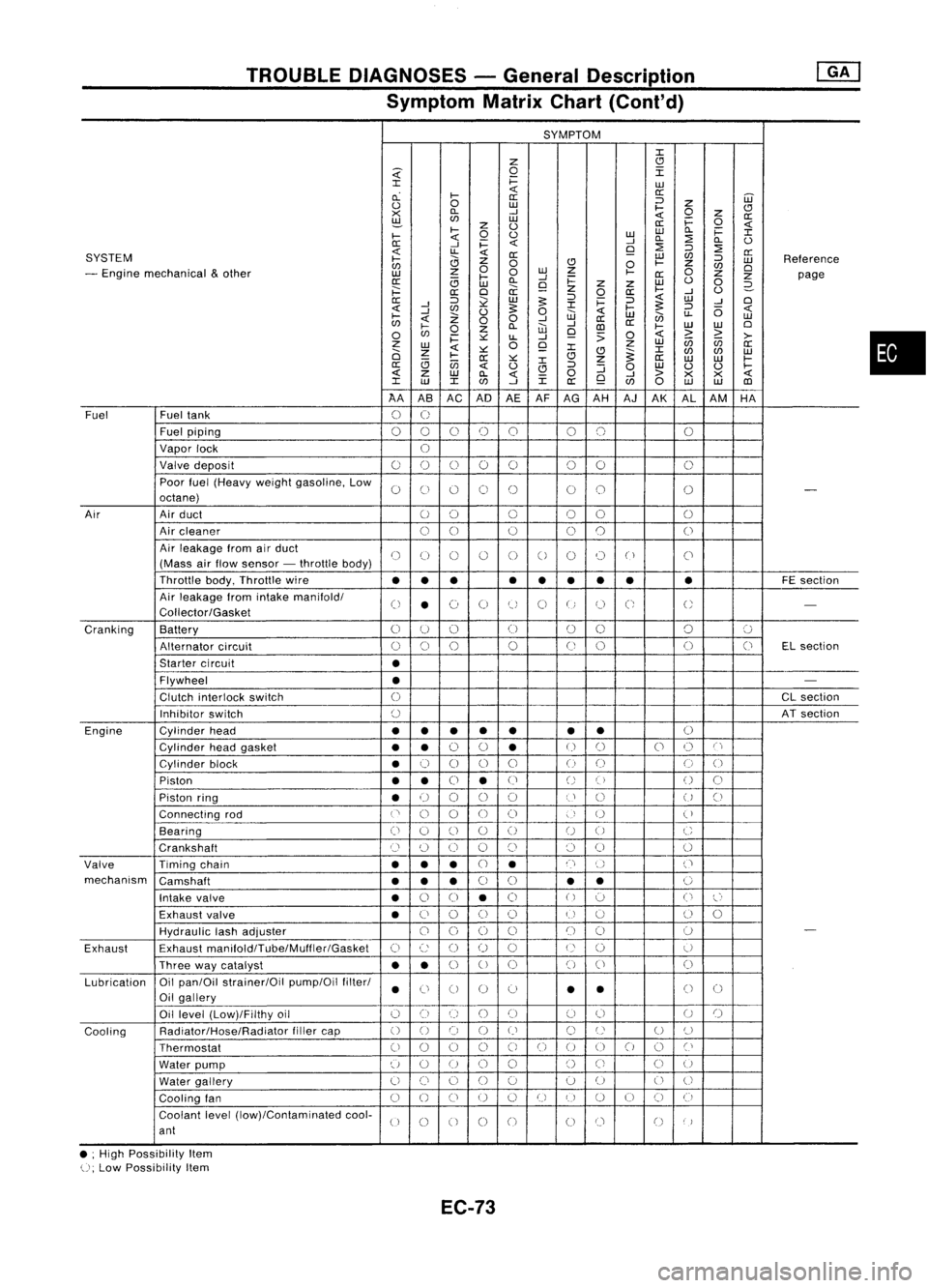
Symptom MatrixChart(Cont'd)
SYMPTOM
J:
Z
CJ
~
0
I
J:
i=
LU
cL
I-
«
a:
a: ::J
UJ
0
0
LU
I-
Z
CJ
><
D..
-'
«
0
z
a:
~
LU
i=
0
z
0
a:
«
I-
0
0
LULU
D..
i=
J:
I-
«
-'
D..
:2
D..
0
0:
-'
i=
«
9
:2
::J
:2
SYSTEM
«
LL
«
0:
LU
C/J
a:
I-
0
Z
0
CJ
0
I-
Z
::J
LU
Reference
C/J
0
C/J
0
- Engine mechanical
&
other
z
0
LU
Z
I-
0
LU
I-
-'
0:
Z
Z
page
0:
(3
LU
D..
9
i=
z
Z
LU
0
0
2-
;:::
a:
0
a:
z
0
a:
I-
-'
0
0:
::J
~
LU
5:
::J
i=
::J
«
LU
-'
0
-'
J:
5:
«
-'
C/J
0
5:
0
«
I-
::J
(5
«
I-
Z
W
LU
en
LL
LU
C/J
«
00
-'
-'
a:
a:
0
I-
0
Z
D..
W
CD
I-
LU
LU
0
C/J
i=
~
LL
-'
9
:>
0
«
>
~
>-
z
0
Z
LU
(ij
C/J
a:
LU
«
~
9
J:
J:
0
Z
CJ
~
C/J
C/J
LU
I-
0:
~
CJ
Z
a:
LU LU
I-
(3
(jj
J:
a:
«
0
CJ
::J
:J
0
LU
0 0
I-
«
z
LU
D..
«
0
-'
>
><><
«
J:
LU
J:
C/J
-'
J:
a:
9
C/J
0
LU LU
CD
AA ASAC AD
AEAF
AG AH AJAK ALAM HA
Fuel Fueltank
0
U
Fuel piping
00 0
()
0 00 0
Vapor lock
U
Valve deposit
00 000 00
0
Poor fuel(Heavy weightgasoline, Low
0
C)
0 0
()
00
0
-
octane)
Air Airduct
00 0
00
0
Air cleaner
00
0
0
0
0
Air leakage fromairduct
()
(J
()
()
0
0
0 0
("
)
C'
(Mass airflow sensor -throttle body)
Throttle body,Throttle wire
••• •
••
•• •
FE
section
Air leakage fromintake manifold/
0
•
(~)
0
tJ
0
U
C;
U
-
Collector/Gasket
Cranking Battery
0
U
()
(J
00 0
':J
Alternator circuit
()
0
0
0
(J
0 0
(J
ELsection
Starter circuit
•
Flywheel
•
-
Clutch interlock switch
0
CL
section
Inhibitor switch
()
ATsection
Engine Cylinderhead
••
• •
• •
•
()
Cylinder headgasket
••
0
0
•
U
()
0
()
C'
Cylinder block
•
0
0 0
0
()
(J
0
0
Piston
••
0
•
(J
()
()
()
0
Piston ring
•
U
00
0
U
()
U
()
Connecting rod
('
0
0
00
)
U
(
)
Bearing
(i
0
()
0
()
U
0
C
Crankshaft
Cl
(~)
0 0
()
()
0
0
Valve Timingchain
•••
CJ
•
n
()
('
mechanism Camshaft
•••
0
0
•
•
0
Intake valve
•
0
0
•
0
()
':J
0
l~'
Exhaust valve
•
C)
0
()
()
U
u
()
0
HydraUlic lashadjuster
00
0
0
()
()
0
-
Exhaust Exhaust
manifoldlTube/Muffler/Gasket
C)
c:
()
()
0
U
()
U
Three waycatalyst
••
0
U
0 0
()
0
Lubrication Oil
pan/Oil strainer/Oil pump/Oilfilter/
•
Ci
0 0
0
•
•
()
0
Oil gallery
Oil level (Low)/Filthy oil
()
0
()
()()
(J
0
U
()
Cooling Radiator/Hose/Radiator
fillercap
()
0 0
()
()
C)
U
U
()
Thermostat
00
0
0
C)
0
()
00
0
Cl
Water pump
u
0
U
0
0
()
Ci
C)
U
Water gallery
U
()
0
()
0 0
U
0
U
Cooling fan
0
()
CJ
U
0
U
I)
U
()
CJ
(i
Coolant level(low)/Contaminated cool-
U
0
0 0
0
00
()
)
ant
• ;High Possibility Item
U;
Low Possibility Item
EC-73
•
Page 995 of 1701
TROUBLEDIAGNOSIS -General Descrip_tio_n
1s_R_1
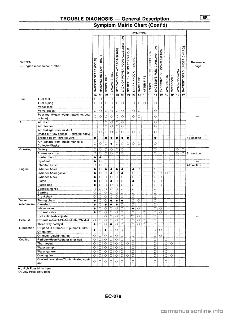
Symptom MatrixChart(Cont'd)
SYMPTOM
z
0
i=
«
W
a:
z
w
w
w
CJ
CJ
....J
....J
0
Z
a:
w
i=
0
a:
(.)
9
8
«
0.. i=
:I:
::J
(.)
z
:2
i='
en
«
:I:
8
:J
0..
(.)
Q
0
f:::.
CJ
:J
:2
a:
a:
:E
z
w
en
SYSTEM
....J
~
0
0
en
z
:J
w
Reference
0
0..
W
a
w
en
Cl
- Engine mechanical
&
other
I-
en
0
z
0
z
z
S:?-
a: 0..
....J
e-
(.)
0
page
I-
«
l-
ii.
9
~
....J
(.)
2-
a:
~
«
w
0
z
w
CJ
Cl
....J ....J
:.:::
0
:J
....J
Z
«
....J
u.
~
I-
(.)
u..
0
a
«
I-
w
«
Z
0
z
enen
w
en
a:
....J
I-
0..
Z
0
WW
:J
W
W
I-
....J
a:
Cl
0 0
9
en
0
a:
z
a:a:
a:
> >
«
0
«
>-
i=
u..
:J
:.:::
ii:
enen
0
:I:
Z Z
W
0
l-
ii:
w w
a:
Ci Ci
:I:
Z
«
w
:.:::
a:
z
en
en
:I:
(.)
(.)
w
CJ
a
I-
:.:::
a:a:
:.:::
w
a
w
w
a:
a:a:
~
a:
a:
:J
en
(.)
«
(.)
I-
(.)
(.)
w
w
w
« «
0
z
w
«
0
0..
«
u..
Z
x x
>>>
«
:I: :I:
a:
w
:I:
....J
Z
en
(l)
«
w w
w
00 0
(l)
1A 1B
1C 1F1H
1R 1S
1M 1J1L1K
1T
1V
1N
1P1X 1Y
Fuel Fueltank
00 0
Fuel piping
00 0000 000
0
Vapor lock
00
Valve deposit
000 000 00 0
Poor fuel(Heavy weightgasoline. Low
0000 00 00
0
-
octane)
Air Airduct
00 00 0
Air cleaner
0
0
00 0
Air leakage fromairduct
00 00 00 0
0 0
0
(Mass airflow sensor -throttle body)
Throttle body.Throttle wire
•
•
•
•
• •
•
FE
section
Air leakage fromintake
manifoldl
00 0
•
0
0 0
00 0
-
Coliector/Gasket
Cranking Battery
0
0
00 0
0 0
0
0
Alternator circuit
00
00
0
0 0
00
EL
section
Starter circuit
••
Flywheel
•
0
-
Inhibitor switch
00
ATsection
Engine Cylinderhead
•
0
•
•
••
•
0
0
Cylinder headgasket
•
0
()
•
0
•
0
0
00
Cylinder block
•
0
()
0 00 0 00
Piston
•
0
0
•
0
0
•
0
0
Piston ring
•
0
00 0
0 0 00
Connecting rod
00 00
00 0 0
Bearing
000 000 0
0
Crankshaft
00
0 0
0
0 0
0
Valve Timingchain
•
0
0
••
•
0
0 0
mechanism Camshaft
•
0
•• •
0
0 0
Intake valve
•
0
00 0
0
•
0
0
0
Exhaust valve
•
0
00 00 0000
Hydraulic lashadjuster
0000
'0
0 0
-
Exhaust Exhaust
manifoldlTube/Mulfler/Gasket
00
00 0
0
00
0 0
Three waycatalyst
•
0
0
•
0
0 000 0
Lubrication Oilpan/Oil strainer/Oil pump/Oilfilterl
000
0
0 0
0
Oil gallery
••
Oil level (Low)/Filthy oil
00 0000
0 0
0
Cooling Radiator/Hose/Radiator fillercap
00
0 00
0 0 00
Thermostat
00
00 0
0 00 0
00
Water pump
000 000 0 0
0
Water gallery
00 00 00
0 0
0
Cooling fan
00 0
00
0 0
0 0
0
0
Coolant level(low)/Contaminated cool-
00
0000
0 0
0
ant
• ;High Possibility Item
0; Low Possibility Item
EC-276
Page 1097 of 1701
KV11290220SEF833
SEF834
SEF835 INJECTION
NOZZLE ~
Cleaning (Coni'd)
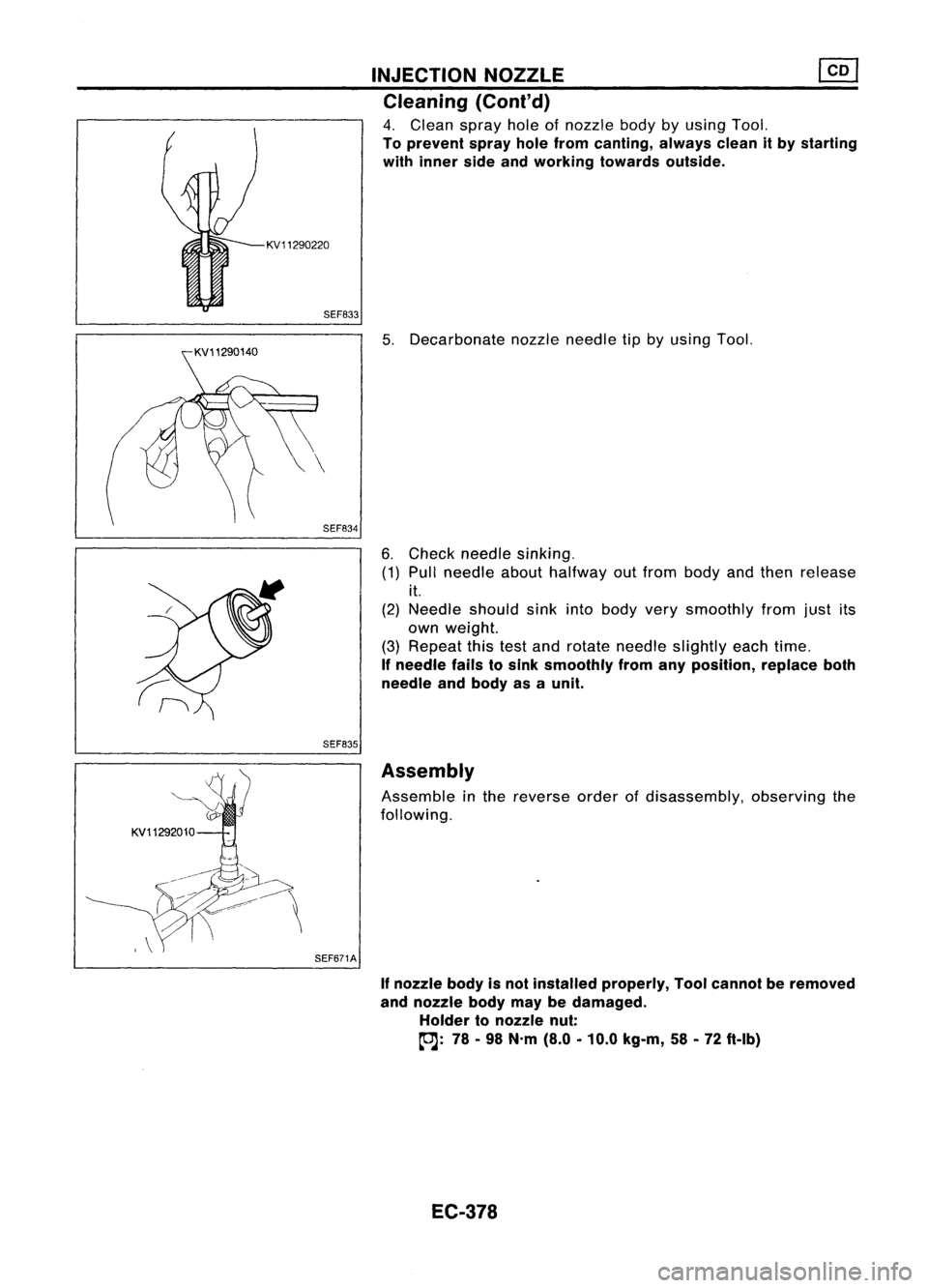
4. Clean sprayholeofnozzle bodybyusing Tool.
To prevent sprayholefrom canting, alwayscleanitby starting
with inner sideandworking towardsoutside.
5. Decarbonate nozzleneedle tipbyusing Tool.
6. Check needle sinking.
(1) Pull needle abouthalfway outfrom body andthen release
it.
(2) Needle shouldsinkintobody verysmoothly fromjustits
own weight.
(3) Repeat thistestand rotate needle slightly eachtime.
If
needle failstosink smoothly fromanyposition, replaceboth
needle andbody asaunit.
KV11292010 SEF671AAssembly
Assemble inthe reverse orderofdisassembly, observingthe
following.
If
nozzle bodyisnot installed properly, Toolcannot beremoved
and nozzle bodymaybedamaged.
Holder tonozzle nut:
(OJ:
78-98 N'm (8.0-10.0 kg-m, 58-72 ft-Ib)
EC-378
Page 1145 of 1701
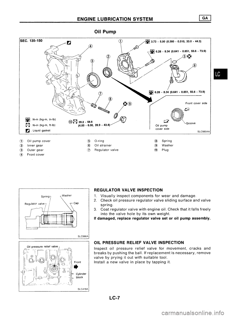
ENGINELUBRICATION SYSTEM
SEC.
135.150
lil
N.m(kg-m, in-Ib)
~. N.m(kg-m, ft-Ib)
rJ .
Liquid gasket
Oil
Pump
Frontcover side
a~:oo"
Oil pump
cover side
SLC985AA
•
CD
Oilpump cover
@
Inner gear
@
Outer gear
@
Front cover
I])
O-ring
@J
Oilstrainer
(J)
Regulator valve
@
Spring
@
Washer
@)
Plug
Spring]
I
Regulator valve
7
I
REGULATOR
VALVEINSPECTION
1. Visually inspectcomponents forwear anddamage.
2. Check oilpressure regulator valvesliding surface andvalve
spring.
3. Coat regulator valvewithengine oil.Check thatitfalls freely
into thevalve holebyitsown weight.
If damaged, replaceregulator valvesetoroil pump assembly.
SLC986A OILPRESSURE RELIEFVALVEINSPECTION
Inspect oilpressure reliefvalve formovement, cracksand
breaks bypushing theball. Ifreplacement isnecessary, remove
valve byprying itout with suitable tool.
Front Installanew valve inplace bytapping it.
•
Cylinder
block
SLC418A
LC-7
Page 1158 of 1701
ENGINELUBRICATION SYSTEM
Oil Pump (Cont'd)
INSPECTION
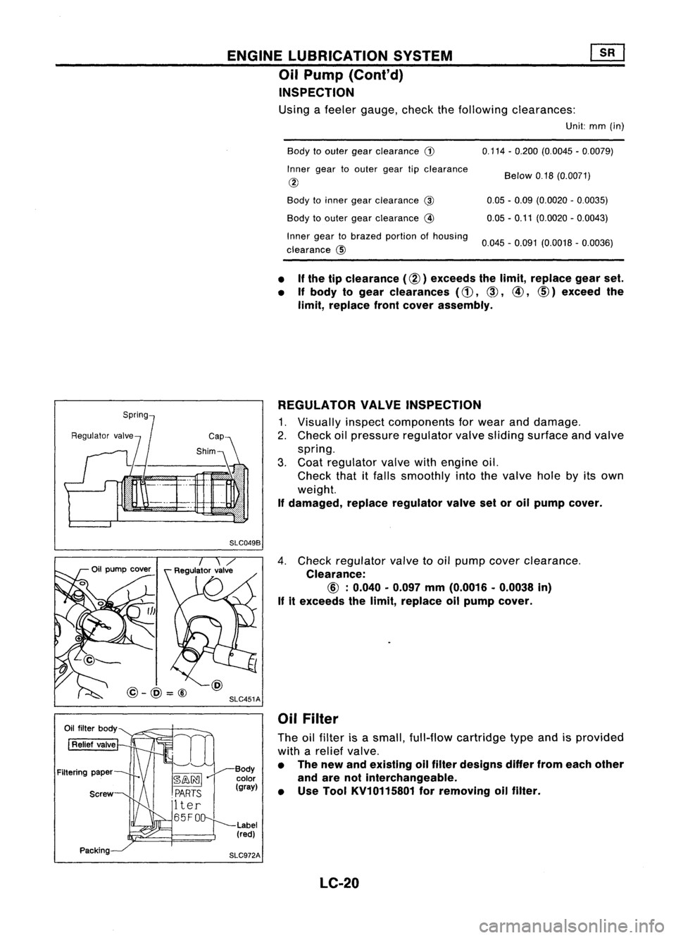
Using afeeler gauge, checkthefollowing clearances:
Unit:mm(in)
Body toouter gearclearance
G)
Inner geartoouter geartipclearance
@
Body toinner gearclearance
@
Body toouter gearclearance
@
Inner geartobrazed portionofhousing
clearance @ 0.114
-0.200 (0.0045 -0.0079)
Below 0.18(0.0071)
0.05 -0.09 (0.0020 -0.0035)
0.05 -0.11 (0.0020 -0.0043)
0.045 -0.091 (0.0018 -0.0036)
• If
the tipclearance (@) exceeds thelimit, replace gearset.
• Ifbody togear clearances
(d),
CID,
@,
CID)
exceed the
limit, replace frontcover assembly.
REGULATOR VALVEINSPECTION
1. Visually inspectcomponents forwear anddamage.
2. Check oilpressure regulator valvesliding surface andvalve
spring.
3. Coat regulator valvewithengine oil.
Check thatitfalls smoothly intothevalve holebyitsown
weight.
If damaged, replaceregulator valvesetoroil pump cover.
SLC049B
SLC451A
@-@=@
4.
Check regulator valvetooil pump cover clearance.
Clearance:
If
itexceeds thelimit, replace oilpump cover.
Oil Filter
The oilfilter isasmall, full-flow cartridge typeandisprovided
with arelief valve.
• The new andeXisting oilfilter designs differfromeach other
and arenotinterchangeable.
• Use Tool KV10115801 forremoving oilfilter.
LC-20
Page 1167 of 1701
•
less
than 0.18(0.0071)
0.12
-0.20 (0.0047 -0.0079)
0.05 -0.09 (0.0020 -0.0035)
0.05 -0.11 (0.0020 -0.0043)
0.05 -0.09 (0.0020 -0.0035)
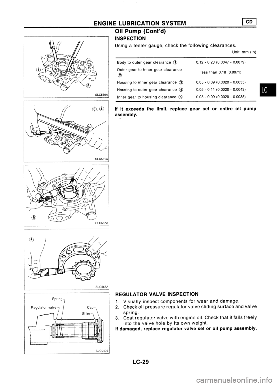
Body
toouter gearclearance
CD
Outer geartoinner gearclearance
@
Housing toinner gearclearance @
Housing toouter gearclearance
@
Inner geartohousing clearance @
If
itexceeds thelimit, replace gearsetorentire oilpump
assembly.
SLC560A
ENGINE
LUBRICATION SYSTEM
Oil Pump (Cont'd)
INSPECTION
Using afeeler gauge, checkthefollowing clearances.
Unit:mm(in)
SLC561C
SLC568A REGULATOR VALVEINSPECTION
1. Visually inspectcomponents forwear anddamage.
2. Check oilpressure regulator valvesliding surface andvalve
spring.
3. Coat regulator valvewithengine oil.Check that
it
falls freely
into thevalve holebyitsown weight.
If
damaged, replaceregulator valvesetoroil pump assembly.
SLC049B LC-29
Page 1326 of 1701
![NISSAN ALMERA N15 1995 Service Manual CYLINDERBLOCK
@[]
Inspection (Cont'd)
• Ifeither bearing, crankshaft orcylinder blockisreplaced
with anew one, select mainbearing according tothe fol-
lowing table.These numbers arepunched in NISSAN ALMERA N15 1995 Service Manual CYLINDERBLOCK
@[]
Inspection (Cont'd)
• Ifeither bearing, crankshaft orcylinder blockisreplaced
with anew one, select mainbearing according tothe fol-
lowing table.These numbers arepunched in](/manual-img/5/57349/w960_57349-1325.png)
CYLINDERBLOCK
@[]
Inspection (Cont'd)
• Ifeither bearing, crankshaft orcylinder blockisreplaced
with anew one, select mainbearing according tothe fol-
lowing table.These numbers arepunched ineither Arabic
or Roman numerals.
Mainbearing housing gradenumber
0 1
2
Main bearing gradenumber
0 0 12
Crankshaft mainjour-
1
1
2
3
nal grade number
22
3
4
•
~NO'1 mainjournal gradenumber
NO.2 No.4
"" No. 3/ No.5
~'S"bci~
0000 "')N1
~ o.
- Counterweight
"\ /i
SEM706DAIdentification
color:
Grade 0
Grade 1
Grade 2
Grade 3
Grade 4 Yellow
Green
Brown
BlackBlue
No. 1journal gradenumber
~No.5
Q
Front
0
SEM706A
For
example:
Main journal gradenumber: 1
Crankshaft journalgradenumber: 2
Main bearing gradenumber
=
1
+
2
Main bearing thickness:
Refer toSOS (EM-175).
3
SEM507A CONNECTING
RODBEARING CLEARANCE (Bigend)
1. Install connecting rodbearing toconnecting rodand cap.
2. Install connecting rodcap with bearing toconnecting rod.
Apply oiltothe thread portion ofbolts andseating surface of
nuts.
toJ:
37-45 N'm (3.8-4.6 kg-m, 27-33 ft-Ib)
3. Measure insidediameter "C"ofbearing.
EM-147