Page 1358 of 1701

SEF289HSGI233
SGI234 PRECAUTIONS
General Precautions (Cont'd)
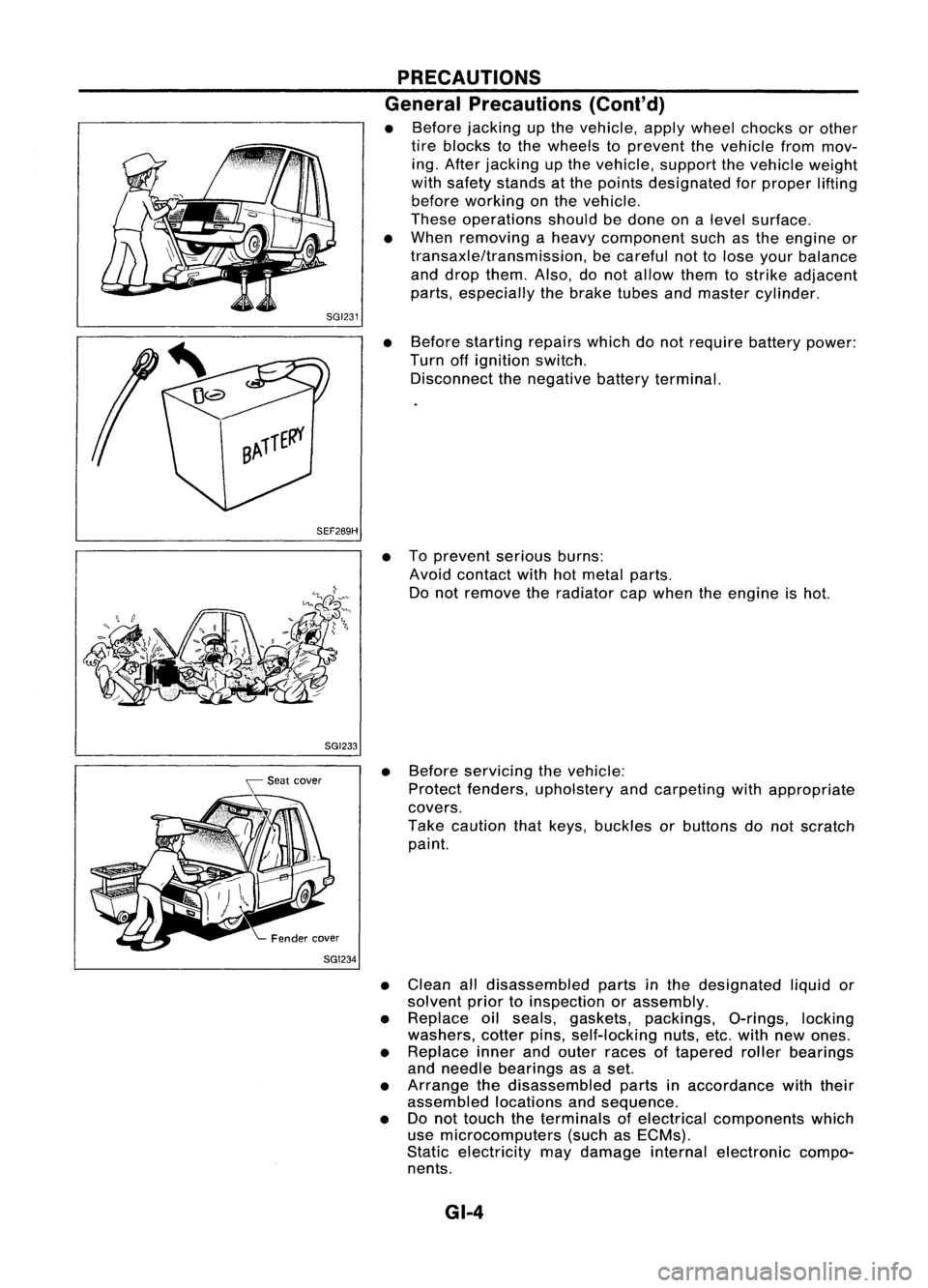
• Before jacking upthe vehicle, applywheel chocks orother
tire blocks tothe wheels toprevent thevehicle frommov-
ing. After jacking upthe vehicle, supportthevehicle weight
with safety stands atthe points designated forproper lifting
before working onthe vehicle.
These operations shouldbedone onalevel surface.
• When removing aheavy component suchasthe engine or
transaxle/transmission, becareful nottolose your balance
and drop them. Also,donot allow themtostrike adjacent
parts, especially thebrake tubesandmaster cylinder.
• Before starting repairswhichdonot require batterypower:
Turn offignition switch.
Disconnect thenegative batteryterminal.
• Toprevent seriousburns:
Avoid contact withhotmetal parts.
Do not remove theradiator capwhen theengine ishot.
• Before servicing thevehicle:
Protect fenders, upholstery andcarpeting withappropriate
covers.
Take caution thatkeys, buckles orbuttons donot scratch
paint.
• Clean alldisassembled partsinthe designated liquidor
solvent priortoinspection orassembly.
• Replace oilseals, gaskets, packings, O-rings,locking
washers, cotterpins,self-locking nuts,etc.with newones.
• Replace innerandouter races oftapered rollerbearings
and needle bearings asaset.
• Arrange thedisassembled partsinaccordance withtheir
assembled locationsandsequence.
• Donot touch theterminals ofelectrical components which
use microcomputers (suchasECMs).
Static electricity maydamage internalelectronic compo-
nents.
GI-4
Page 1368 of 1701

Normallyopen
HOW
TOREAD WIRING DIAGRAMS
Description (Cont'd)
SWITCH POSITIONS
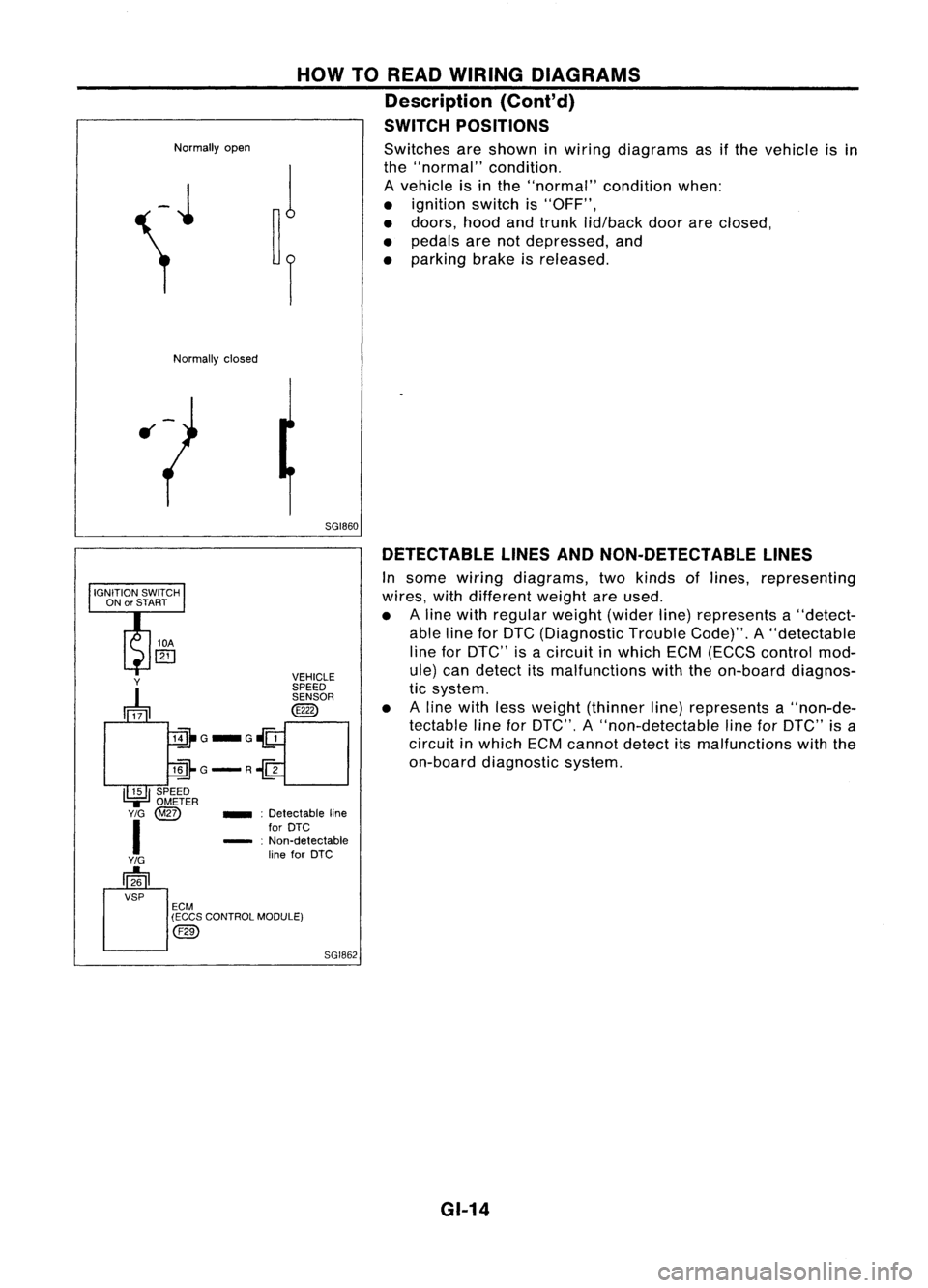
Switches areshown inwiring diagrams asifthe vehicle isin
the "normal" condition.
A vehicle isin the "normal" conditionwhen:
• ignition switchis"OFF",
• doors, hoodandtrunk lid/back doorareclosed,
• pedals arenotdepressed, and
• parking brakeisreleased.
Normally closed
5GI860DETECTABLE LINESANDNON-DETECTABLE LINES
In some wiring diagrams, twokinds oflines, representing
wires, withdifferent weightareused.
• Aline with regular weight(widerline)represents a"detect-
able lineforDTC (Diagnostic TroubleCode)".A"detectable
line forDTC" isacircuit inwhich ECM(ECCS control mod-
ule) candetect itsmalfunctions withtheon-board diagnos-
tic system.
• Aline with lessweight (thinner line)represents a"non-de-
tectable lineforDTC", A"non-detectable lineforDTC" isa
circuit inwhich ECMcannot detectitsmalfunctions withthe
on-board diagnostic system.
SGI862
_
:Detectable line
for DTC
- :Non-detectable
line forDTC
Y
~ VEHICLE
SPEED SENSOR
@
lill-G_G~
llli-G-R~
I~I
SPEED
.,=
OMETER
Y/G
@Z)
I
Y/G
[]26
VSP ECM
(ECCS CONTROL MODULE)
@)
GI-14
Page 1392 of 1701
IDENTIFICATIONINFORMATION
Identification Number(Cont'd)
IDENTIFICATION PLATE
Europe
NISSAN MOTORCO.,LTD.JAPAN
I
It
I
&,
it
0
ill
iliO
1-
ill
kg
2-
&,
kg
Tri'[
11
COlOR.iRIM
&
&,
TYP
fARBE,POLSl
i
Lilli
Except
Europe
NISSAN MOTORCO.,LTD. JAPAN
~ it
ii:J
b
CHASS~ NO
NO DECHASIS
MODEL
MDDELO
o
~;::~:~~NlctDN
.:t;..-
ENGINE
~:,... MOTOR
~ ';;Y
3;..-
TRANS~
AXl.£
7P;;<'.
ll!AIIS.EJt:
M4DEINJAPAN
o
CC
1
Type approval number
2 Vehicle identification
number (Chassis number)
3 Gross vehicle weight
4 Gross combination weight
Gross vehicle weight
+
Gross trailing capacity
(Weight)
5 Gross axleweight (Front)
6 Gross axleweight (Rear)
7 Type
8 Body colorcode
9 Trim color code
10 Model
11 Engine model
12 Engine displacement
13 Transaxle model
14 Axle model
SGI704
ENGINE SERIALNUMBER
GA 14DE, GA15DE and
GA16DE engine
£~b-=~~rrf~)
(J~~~6
Front
c:::?
SR20DE
engine CD20engine
SGI912
MANUAL TRANSAXLE NUMBER
RS5F30A, RS5F31AandRS5F32A AUTOMATIC
TRANSAXLE NUMBER
SGI913 GI-38 SGI656
Page 1409 of 1701

PRECAUTIONSANDPREPARATION
HFC-134a (R-134a)ServiceToolsandEquipment
(Cont'd)
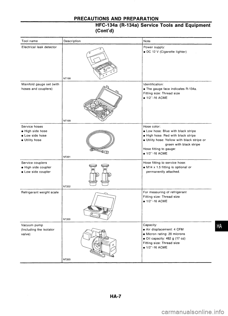
Tool name
Electrical leakdetector
Manifold gaugeset(with
hoses andcouplers)
Service hoses
• High sidehose
• Low side hose
• Utility hose
Service couplers
• High sidecoupler
• Low side coupler
Refrigerant weightscale
Vacuum pump
(Including theisolator
valve) Description
NT19S
NT199
NT201
NT202
NT200
NT203 HA-7
Note
Power supply:
• DC 12V(Cigarette lighter)
Identification:
• The gauge faceindicates R-134a.
Filling size:Thread size
• 1/2"-16 ACME
Hose color:
• Low hose: Bluewithblack stripe
• High hose: Redwith black stripe
• Utility hose:Yellow withblack stripe or
green withblack stripe
Hose filting togauge:
• 1/2"-16 ACME
Hose filling to
service
hose:
• M14 x1.5 fitting isoptional or
permanently attached.
For measuring ofrefrigerant
Fitting size:Thread size
.1/2"-16 ACME
Capacity:
• Air displacement: 4CFM
• Micron rating:20microns
• Oil capacity: 482g(17 oz)
Fitting size:Thread size
.1/2"-16 ACME
•
Page 1411 of 1701

Open
Close
AIC
service valve
Counterclockwise
Clockwise
Shut
offvalve rotation
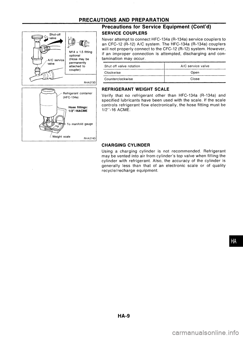
Never
attempt toconnect HFC-134a (R-134a)servicecouplers to
an CFC-12 (R-12)
A/C
system. TheHFC-134a (R-134a)couplers
will notproperly connecttothe CFC-12 (R-12)system. However,
if an improper connection isattempted, discharging andcon-
tamination mayoccur.
REFRIGERANT WEIGHTSCALE
Verify thatnorefrigerant otherthanHFC-134a (R-134a)and
specified lubricants havebeenusedwiththescale. Ifthe scale
controls refrigerant flowelectronically, thehose fitting mustbe
1/2"-16 ACME.
RHA274D
PRECAUTIONS
ANDPREPARATION
Precautions forService Equipment (Cont'd)
SERVICE COUPLERS
RHA273D
M14
x
1.5 fitting
optional (Hose maybe
permanently
attached to
coupler)
Hose fittings:
1/2"-16ACME
To manifold gauge
CHARGING CYLINDER
Using acharging cylinderisnot recommended. Refrigerant
may bevented intoairfrom cylinder's topvalve whenfilling the
cylinder withrefrigerant. Also,theaccuracy ofthe cylinder is
generally lessthan thatofan electronic scaleorofquality
recycle/recharge equipment.
•
HA-9
Page:
< prev 1-8 9-16 17-24