Page 34 of 1701

(atP,)
p,
(Full throttle position)
~ThrOttle drum
Direction U
, ,-- p,
t
I ~.
(Idling
--r ~_ .)
position)
I
Direction T
Engine side"
bracket (at
P,)
~ Adjusting tube
Lock plate ON-VEHICLE
SERVICE
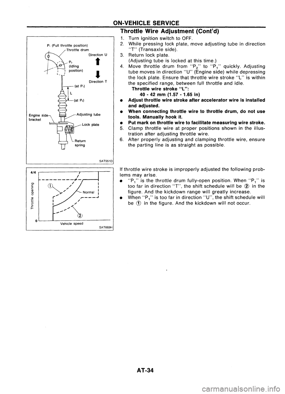
Throttle WireAdjustment (Cont'd)
1. Turn ignition switchtoOFF.
2. While pressing lockplate, moveadjusting tubeindirection
"T" (Transaxle side).
3. Return lockplate.
(Adjusting tubeislocked atthis time.)
4. Move throttle drumfrom
"P2"
to
"P
1"
quickly. Adjusting
tube moves indirection "U"(Engine side)while depressing
the lock plate. Ensure thatthrottle wirestroke "L"iswithin
the specified range,between fullthrottle andidle.
Throttle wirestroke "L":
40 -42
mm
(1.57 -1.65
in)
• Adjust throttle wirestroke afteraccelerator wireisinstalled
and adjusted.
• When connecting throttlewiretothrottle drum,donot use
tools. Manually hookit.
• Put mark onthrottle wiretofacilitate measuring wirestroke.
5. Clamp throttle wireatproper positions showninthe illus-
tration afteradjusting throttlewire.
6. After properly adjusting andclamping throttlewire,ensure
the parting lineisas straight aspossible.
SAT551D
4/4
Vehiclespeed
If
throttle wirestroke isimproperly adjustedthefollowing prob-
lems mayarise.
• "P
1"
isthe throttle drumfully-open position.When"P
1"
is
too farindirection
"T",
theshift schedule willbe
@
inthe
figure. Andthekickdown rangewillgreatly increase.
• When
"P1"
istoo farindirection "U",theshift schedule will
be
CD
inthe figure. Andthekickdown willnotoccur.
SAT669H
I
I
Normal :
,- .J
,/
/
,,~/~
/
---------1--
,/
'//
r-/
I
I
o
0>
c:
C
Q)
0-
o
~
2
£
I-
AT-34
Page 276 of 1701

SBR995
SBR419C AIR
BLEEDING
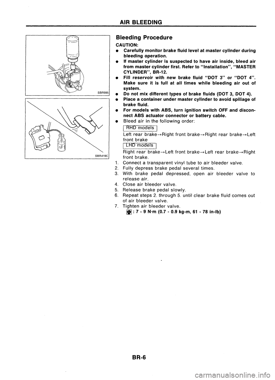
Bleeding Procedure
CAUTION:
• Carefully monitorbrakefluidlevel atmaster cylinder during
bleeding operation.
• Ifmaster cylinder issuspected tohave airinside, bleedair
from master cylinder first.Refer to"Installation", "MASTER
CYLINDER", BR-12.
• Fill reservoir withnewbrake fluid"DOT 3"or"DOT
4".
Make sureitis full atall times whilebleeding airout of
system.
• Donot mix different typesofbrake fluids(DOT3,DOT 4).
• Place acontainer undermaster cylinder toavoid spillage of
brake fluid.
• For models withABS, turnignition switchOFFanddiscon-
nect ABS actuator connector orbattery cable.
• Bleed airinthe following order:
I
RHO models
I
Left rear brake-+Right frontbrake-+Right rearbrake-+Left
front brake
I
LAD models
I
Right rearbrake-+Left frontbrake-+Left rearbrake-+Right
front brake.
1. Connect atransparent vinyltubetoair bleeder valve.
2. Fully depress brakepedalseveral times.
3. With brake pedaldepressed, openairbleeder valveto
release air.
4. Close airbleeder valve.
5. Release brakepedalslowly.
6. Repeat steps2.through 5.until clear brake fluidcomes out
of air bleeder valve.
7. Tighten airbleeder valve.
~: 7-
9 N.m (0.7-0.9 kg-m, 61-78 in-Ib)
BR-6
Page 308 of 1701

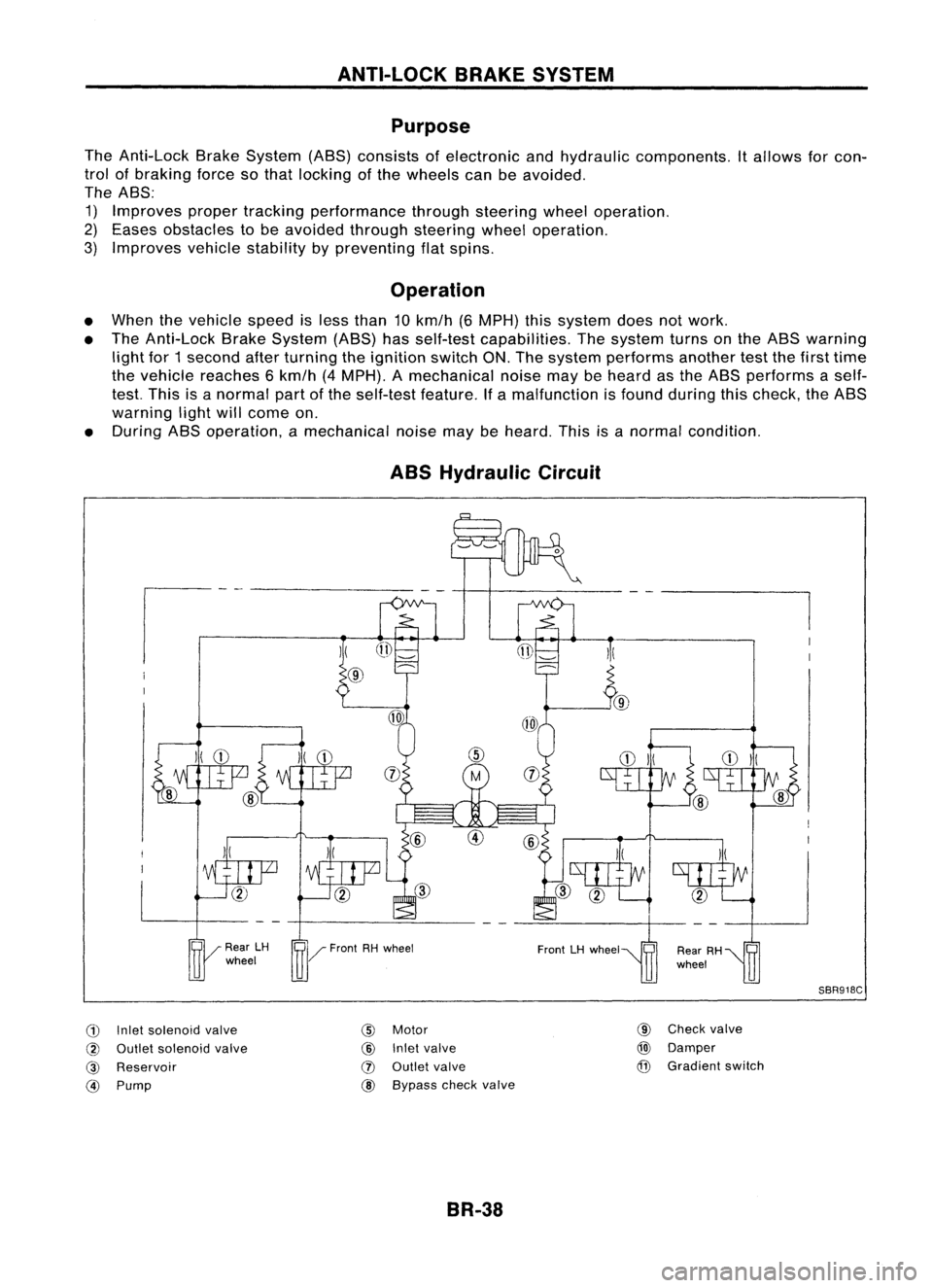
ANTI-LOCKBRAKESYSTEM
Purpose
The Anti-Lock BrakeSystem (ABS)consists ofelectronic andhydraulic components. Itallows forcon-
trol ofbraking forcesothat locking ofthe wheels canbeavoided.
The ABS:
1) Improves propertracking performance throughsteering wheeloperation.
2) Eases obstacles tobe avoided throughsteering wheeloperation.
3) Improves vehiclestability bypreventing flatspins.
Operation
• When thevehicle speedisless than 10km/h (6MPH) thissystem doesnotwork.
• The Anti-Lock BrakeSystem (ABS)hasself-test capabilities. Thesystem turnsonthe ABS warning
light for1second afterturning theignition switchON.The system performs anothertestthefirst time
the vehicle reaches 6km/h (4MPH). Amechanical noisemaybeheard asthe ABS performs aself-
test. This isanormal partofthe self-test feature.Ifa malfunction isfound during thischeck, theABS
warning lightwillcome on.
• During ABSoperation, amechanical noisemaybeheard. Thisisanormal condition.
ABS Hydraulic Circuit
G)
Inletsolenoid valve
@
Outlet solenoid valve
@
Reservoir
@)
Pump
)(
@
@
Motor
@
Inletvalve
(J)
Outlet valve
@ Bypass checkvalve
BR-38 @
Check valve
@)
Damper
@
Gradient switch
SBR918C
Page 315 of 1701
ANTI-LOCKBRAKESYSTEM
Wiring Diagram -ABS -
BR-ABS-01
•
ABS
CONTROL
UNIT
(B111)
LHDmodels
@:
RHOmodels
Refer
to
EL-POWER.
FUSE
BLOCK
(JIB)
~
GY
ffi
IGN
SW
Y
I~I COMBINATION
METER
(ABS WARNING
LAMP)
~@
LIB
@
I
GY
LIB
$-------$
GY (~) LIB
I-
e-
LIB~ ToBR-ABS-O?
I
LIB
13-0
I
FAIL
LAMP
IGNITION
SWITCH
ON orSTART
STOP
DEPRESED LAMP
SWITCH
RELEASED ~
~
P!L
•
~:I
P!L
rn~
I
JUNCTION
BOX
NO.2
(JOINT
CONNECTORS)
1!:i=!J~
PIL
~~
•
PIL
lelIl
9F'~
P!L
14-81
STOP
LAMP
SW
Fa~
l..1..@
B ~~(B115)
5 6
TI1910
1112 W
Refer
tolast page
(Foldout page).
~---------------------------------,
L ~
HBR002
BR-45
Page 316 of 1701
ANTI-LOCKBRAKESYSTEM
Wiring Diagram -ABS -(Coni' d)
BR-ABS-02
ABS
CONTROL
UNIT
(!ID1)
OrAG
L TXD RXD
~ 1~61~
ORIB ~ GY!L GIB
I$~ ~
~ciJ~ ---
~~I
ORIB
GY/L GIB
It It
GY!L
GIB
cr
l I~
i~MO~o~?ic~g~)
~:
JOINT CONNECTOR-5
~ 1*.21~:
GY/L GIB
I I
GY/L
GIB
m
r1l
ORIB
rtl
FUSE
Referto
7 .5A BLOCK EL-POWER.
rn
(JIB)
~
IGNITION
SWITCH
ON orSTART
I
DATALINK
CONNECTOR
FOR CONSULT
(M13)
-----------------------
<0:
LHDmodels
RHOmode Is
@:
GAengine andSRengine
@:
CD20engine
~f1
<0
10
6
*2
<0
9
'
3
,
~~(~)
56j819101112 W
~(~24)
~OR
Refer
tolast page
(Foldout page).
HBR003
BR-46
Page 325 of 1701

TROUBLEDIAGNOSES
Self-diagnosis (ForEurope) (Cont'd)
MALFUNCTION CODE/SYMPTOM CHART
Code No.
Malfunctioningpart Diagnostic
procedure
(No. ofwarning lampflashes)
45
Actuator
frontleftoutlet solenoid valve
3
46
Actuator
frontleftinlet solenoid valve
3
41
Actuator
frontrightoutlet solenoid valve
3
42
Actuator
frontrightinletsolenoid valve
3
51
Actuator
rearright outlet solenoid valve
3
52
Actuatorrearright inletsolenoid valve
3
55
Actuator
rearleftoutlet solenoid valve
3
56
Actuator
rearleftinlet solenoid valve
3
25
Frontleftsensor (open-circuit)
4
26
Front
leftsensor (short-circuit)
4
21
Frontrightsensor (open-circuit)
4
22
Front
rightsensor (short-circuit)
4
35
Rearleftsensor (open-circuit)
4
36
Rear
leftsensor (short-circuit)
4
31
Rearrightsensor (open-circuit)
4
32
Rearrightsensor (short-circuit)
4
18
Sensorrotor
4
61
Actuatormotorormotor relay
5
63
Solenoidvalverelay
6
57
Powersupply (Lowvoltage)
7
71
Controlunit
8
Control unitpower supply circuit
Warning lampstays onwhen igni-Warning
lampbulbcircuit
tion switch isturned on Control
unitorcontrol unitconnector
2
Solenoid valverelaystuck
Power supply forsolenoid valverelaycoil
Warning lampstays on,during
Controlunit
-
self-diagnosis
Warning lampdoesnotcome onFuse, warning lampbulborwarning lampcircuit
1
when ignition switchisturned onControl unit
Warning lampdoes notcome on
Control unit
during self-diagnosis
-
Pedal vibration andnoise
-
9
Long stopping distance
-
10
Unexpected pedalaction
-
11
ABS does notwork
-
12
ABS works frequently
-
13
BR-55
•
Page 326 of 1701

TROUBLEDIAGNOSES
Self-diagnosis (ExceptEurope)
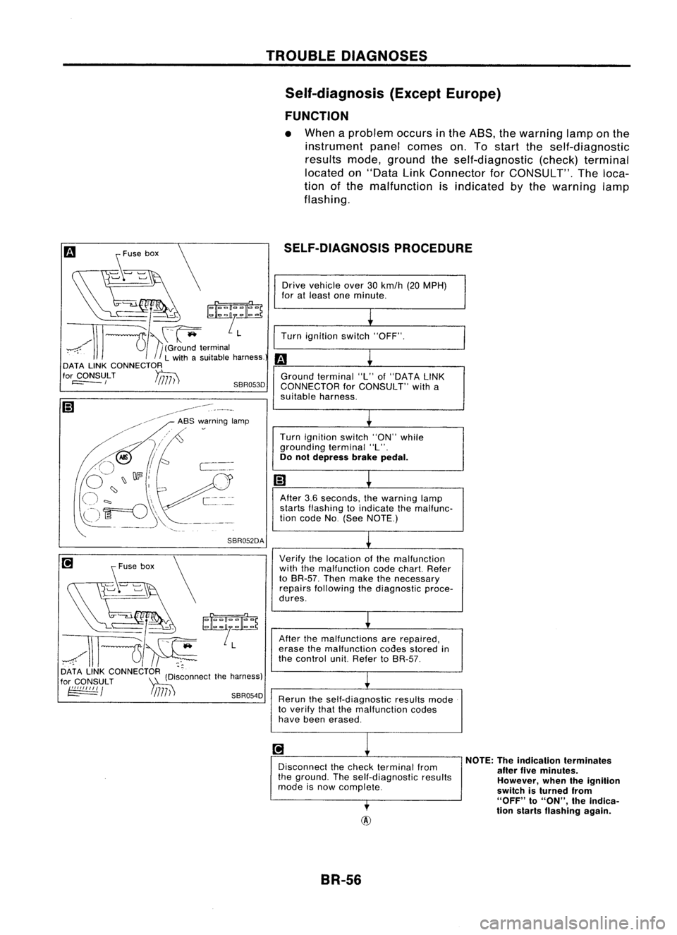
FUNCTION
• When aproblem occursinthe ASS, thewarning lamponthe
instrument panelcomes on.Tostart theself-diagnostic
results mode,ground theself-diagnostic (check)terminal
located on"Data LinkConnector forCONSULT". Theloca-
tion ofthe malfunction isindicated bythe warning lamp
flashing.
SELF-DIAGNOSIS PROCEDURE
[i
s~'~" \
~/''':~~
~/\\l---u~
DATA LINKCONNECTOR (D'.ctthe harness)
for
CONSULT
~Isconne
~ / !
/717) ')
SBR054D
Drive
vehicle over30km/h (20MPH)
for atleast oneminute.
~
Turn ignition switch"OFF".
m
L
Ground terminal "L"of"DATA LINK
CONNECTOR forCONSULT" witha
suitable harness.
L
Turn ignition switch"ON"while
grounding terminal"L".
Do not depress brakepedal.
m
~
After 3.6seconds, thewarning lamp
starts flashing toindicate themalfunc-
tion code No(See NOTE.)
~
Verify thelocation ofthe malfunction
with themalfunction codechart. Refer
to BR-57. Thenmake thenecessary
repairs following thediagnostic proce-
dures.
L
After themalfunctions arerepaired,
erase themalfunction codesstored in
the control unit.Refer toBR-57.
~
Rerun theself-diagnostic resultsmode
to verify thatthemalfunction codes
have been erased.
~
1
Disconnect thecheck terminal from
the ground. Theself-diagnostic results
mode isnow complete.
,
NOTE:
Theindication terminates
after fiveminutes.
However, whentheignition
switch isturned from
"OFF"
to
"ON",
theindica-
tion starts flashing again.
BR-56
Page 329 of 1701
![NISSAN ALMERA N15 1995 Service Manual TROUBLEDIAGNOSES
Ii)
NISSAN
CONSULT
EE940.
I
~
I
START
I
SUB
MODE
,
SEF253Q
@]
~
SELECT
SYSTEM
0
ENGINE
AfT
AIRBAG ABS
IVMS
SBR104D
@]
I~
SELECT DIAGMODE
01
I
SELF-DIAG
RESULTS NISSAN ALMERA N15 1995 Service Manual TROUBLEDIAGNOSES
Ii)
NISSAN
CONSULT
EE940.
I
~
I
START
I
SUB
MODE
,
SEF253Q
@]
~
SELECT
SYSTEM
0
ENGINE
AfT
AIRBAG ABS
IVMS
SBR104D
@]
I~
SELECT DIAGMODE
01
I
SELF-DIAG
RESULTS](/manual-img/5/57349/w960_57349-328.png)
TROUBLEDIAGNOSES
Ii)
NISSAN
CONSULT
EE940.
I
~
I
START
I
SUB
MODE
,
SEF253Q
@]
~
SELECT
SYSTEM
0
ENGINE
AfT
AIRBAG ABS
IVMS
SBR104D
@]
I~
SELECT DIAGMODE
01
I
SELF-DIAG
RESULTS
,
I
DATA
MONITOR
I
I
ACTIVE
TEST
I
ECU
PART NUMBER
I
I
SST412B
II
•SELF-DiAG RESULTS.
0
FAILURE DETECTED
TIME
FR RH SENSOR
0
[OPEN)
ERASE
II
PRINT
SBR950C CONSULT
Inspection Procedure
SELF-DIAGNOSIS PROCEDURE
m
1) Turn ignition switchOFF.
2) Connect CONSULT toData LinkCon-
nector forCONSULT.
1) Start engine.
2) Drive vehicle over30km/h (20MPH)
for atleast oneminute.
.
r
(;)
1)Stop vehicle withengine running
and touch "START" onCON-
SUL Tscreen.
• Program
card
AE950: ForAustralia
EE940: ExceptAustralia
(!]
2)Touch "ASS".
lP]
3)Touch "SELF-DIAG RESULTS".
• The screen showsthedetected mal-
function andthetimes ofignition
switch ONand OFF after itoccurred.
Make thenecessary repairsfollowing
the diagnostic procedures.
II
After themalfunctions arerepaired,
erase theself-diagnostic resultsstored
in the control unitbytouching
"ERASE".
Check warning lampfordeactivation
after driving vehicle over30km/h (20
MPH) foratleast oneminute.
Test theASS inasafe area toverify
that itfunctions properly.
Note: "SELF.DlAG RESULTS"screenshowsthedetected malfunction and
the times ofignition switchONand OFF after
it
occurred.
BR-59
•