Page 405 of 1701
STARTINGSYSTEM
Wiring Diagram -START -
MIl MODELS
EL-START-01
U:i=ll
B/W
ON
OFF
'e- .....
ACC
:J
Refer to
EL-POWEA.
ST IGNITION
SWITCH
~
(1):
LHOmode 1s
@:
RHOmodels
@:
GAeng ine and SReng ine
@:
CDengine
@: ForEurope andIsrae 1
@:
Except@
~: Gasoline enginemodels for
Europe, IsraelandAustralia
@:
Except~
*1"'(1)1 @4
,
~~
O~ B/W~ B/W~Ol -B/W
-(Q
LB/W~B/W.J
@
~:
@: ~
~:@
BATTERY
STARTERMOTOR
@TI): ~
@lID:
@
~---------------------~
I I
: ~@
fTIN1@~:
,~mID
I
~ W W ~
R@TI)
~
~ GY
I
GY
•
~~
@lID:ID
B ~oo
~GY
EL-33
HEL
194
Page 406 of 1701
STARTINGSYSTEM
Wiring Diagram -START -(Conl'd)
AIT MODELS
EL-START-02
STARTER MOTOR
~
I
B/Y
m
@:
ForEurope andIsrael
@:
Except@
GAengine
@:
SRengine
~H"'@3 @4
*2 ...
2'
@
1
,
BATTERY
~~
B ~ B
B ~ B
~~
INHIBITOR
SWITCH
@g)
Refer
toEL-POWER.
ST IGNITION
SWITCH
*
I
FUSE
BLOCK
(JIB)
~B
•
IQ~OI
BR
I
OF
SA
J-.
-It
I
1111 --
n
INHIBITOR
u
RELAY
lkjJIlbjdlffi)
G/OR B/Y
lJ
B/Y~B/Y
@:~IOO:@
G/OR ~ G/OR...
G/OR
Iftn
r--------------------,
I I
I~
FmTl
I
: @@lID
@
tIDrnI
@
@W :
: W W :
L
~
~
T
L
R~
'.!J
GY
Refer
tolast page
(Foldout page).
~~
~B ~~
~GY
Iffi\m>
\AW
GY
HEL195
EL-34
Page 407 of 1701

STARTINGSYSTEM
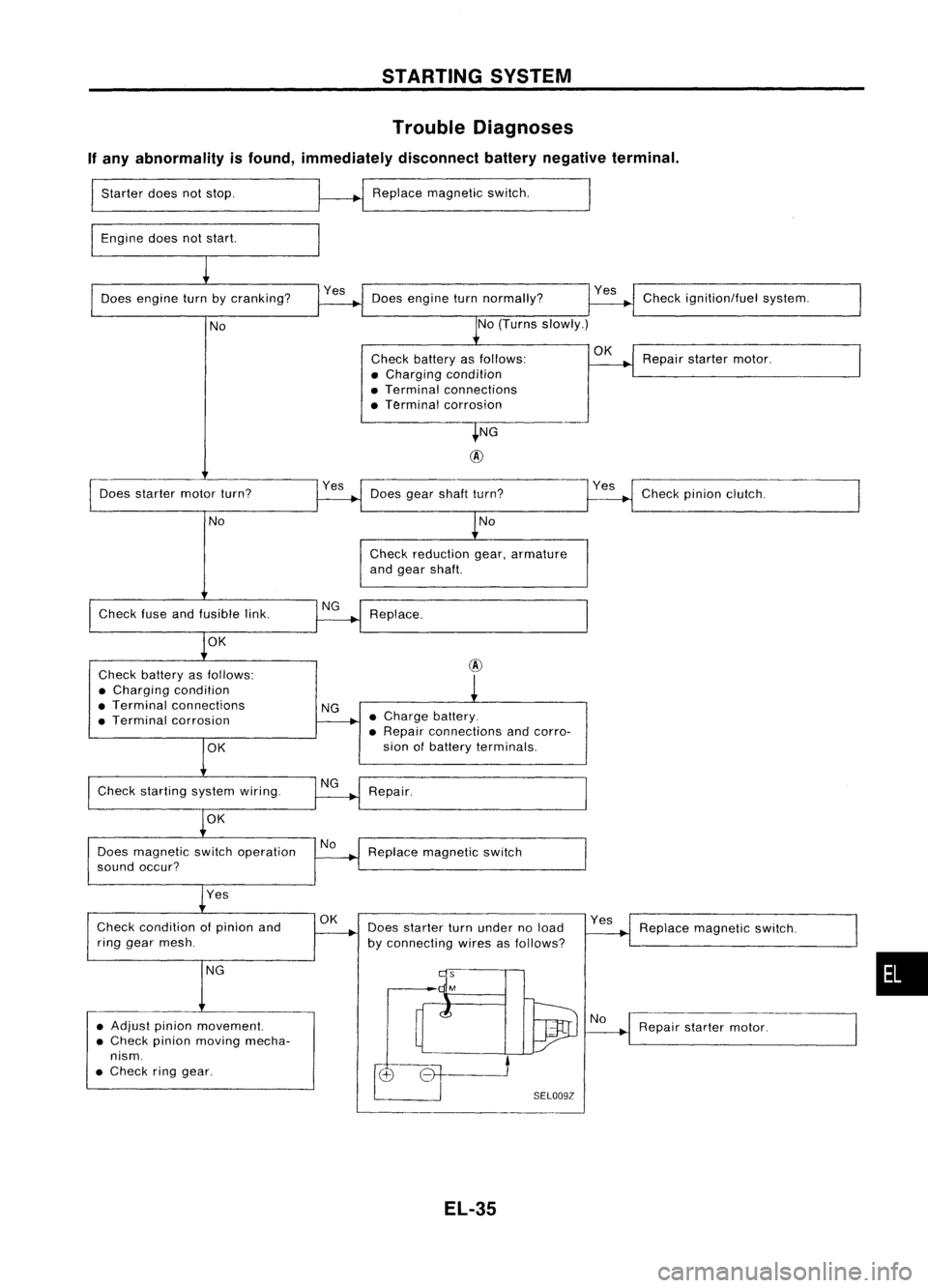
Trouble Diagnoses
If any abnormality isfound, immediately disconnectbatterynegative terminal.
Starter doesnotstop.
Engine doesnotstart. Replace
magnetic switch.
Does engine turnbycranking? Doesengine turnnormally? Check
ignition/fuel system.
No No
(Turns slowly.)
Check battery asfollows:
OK
Repairstarter motor.
• Charging condition
• Terminal connections
• Terminal corrosion
NG
@
Does starter motorturn? Yes
Doesgearshaft turn? Checkpinionclutch.
No No
Check reduction gear,armature
and gear shaft.
Check fuseandfusible link. Replace.
OK
Check battery asfollows:
@
• Charging condition
• Terminal connections
NG
• Terminal corrosion •
Charge battery.
• Repair connections andcorro-
OK
sian
ofbattery terminals.
Check starting systemwiring.
Repair.
OK
Does magnetic switchoperation No
Replace magnetic switch
sound occur?
Yes
Check condition ofpinion and
OK
Doesstarter turnunder noload Yes
Replace magnetic switch.
ring gear mesh.
byconnecting wiresasfollows?
NG
•
• Adjust pinionmovement.
Repairstarter motor.
• Check pinionmoving mecha-
nism .
• Check ringgear.
SELOO9Z
EL-35
Page 424 of 1701
CHARGINGSYSTEM
Wiring Diagram -CHARGE -
GASOLINE ENGINEMODELS
EL-CHARGE-01
Referto
EL-POWER.
LHD models
RHO models
AIT
models
MIT
models
For Europe
Except@
FUSE
BLOCK
(JIB)
~
(0:
@:
@:
@:
@:
@:
@: GAengine
@: SRengine
@:
Withtachometer
@:
Without tachometer
~f1"'@
6,@B
*2 @30 ,@40
*3 @40 ,
@
3
.,
B
!
@QID
IGNITION
SWITCH
ON or START
Refer to
EL-POWER.
FUSIBLE
LINK AND
FUSE BOX
~
~
7.5A
mJ
RIB
lOA
[]]
1~11
Y
COMBINATION
I~
METER
(CHARGE
WARNING
LAMP)
(M30)
~ 1*.31
Y/R
~2 ~Y/R
-ee-~
JOINT ~
()~ CONNECTOR-l~~
~ ()-ID-I
~ Y/R Y/R
RIB R/B@@
Irku@
In-'
~ ~ ,..,JI,.,~
(E26)
'"T-'~
4JOINT
~ @D
IJ¥!I
(E201) (E203) Y
IR
EU
~gNNECTOR
RIB
R/B@@
I @l
<;>
{(100
I
y
~I
Y/R
~~
~@jg)
Y/R
m
RIB
n1-lI
AL TERNATOR ~~~
~-------------------------------,
L
j
~~ ~~~@D
~BR ~B~ B~~,~
rn::rm
BGY Refer
tolast page
(Foldout page).
@,
~
m~
,
r-----------------,
:~~~~~~:
11m ~
GY
ISI
I
I I
L
j
~~
~OR
HEL196
EL-52
Page 426 of 1701

CHARGINGSYSTEM
Trouble Diagnoses
Before conducting analternator test,make surethatthebattery isfully charged. A3D-volt voltmeter and
suitable testprobes arenecessary forthe test. Thealternator canbechecked easilybyreferring tothe
Inspection Table.
Before starting, inspectthefusible link.
WITH IeREGULATOR
Burned-out
bulb.
Replace and
proceed to
"@".
Light "ON"
Light "OFF"
Connect
connector (S,
L) and
ground F
terminal
Engine
speed: 1,500 rpm
(Measure B
terminal
voltage)
Make sure
connector (S,L)is
connected
correctly.
(HITACHI
make)
'See
4)for grounding Fterminal.
(MITSUBISHI
make)
Check or
replace drive
belt.
Light "ON"
Light "OFF"
Disconnect
connector (S,
L) and
ground L
lead wire.
Engine
speed:
1,500 rpm
Lighting
switch "ON"
With
alternator sideLterminal
grounded. internalshortoccurs
when
+
diode isshort-circuited.
Light "ON
Dim
light
Light flickers
Bright light
Light
"ON"
Light
"OFF"
Ignition
switch "ON"
@
1) Use fully charged battery.
2) light: Charge warning light
ACG :Alternator partsexcept I'Cregulator
IC-RG :IC regulator
OK :IC-alternator isingood condition.
3) When reaching "Damaged ACG",remove
alternator fromvehicle anddisassembly, inspect
and correct orreplace faultyparts.
4) *Method ofgrounding Fterminal (HITACHI make
only)
Gasoline enginemodel
Contact tipofwire withbrush andattach
wire toalternator body.
~~~
;;z..'~~.~
~~~/j
S$.~~'
s<(r~, -
Brush liftwire
;;.. ~ Q<:::z"d,l'T7.
~ .. ~ ~-)o,IJ!"-f/
- -~~ C);
0~~/
'~-/i ~-,~
-~j~n
- <::::; -~ \•
'" 1A/-'
SEL030Z
5) Terminals
"S","l","B"
and
"E"
aremarked onrear cover ofalternator.
EL-54
Page 441 of 1701

HEADLAMP-Daytime LightSystem -
System Description
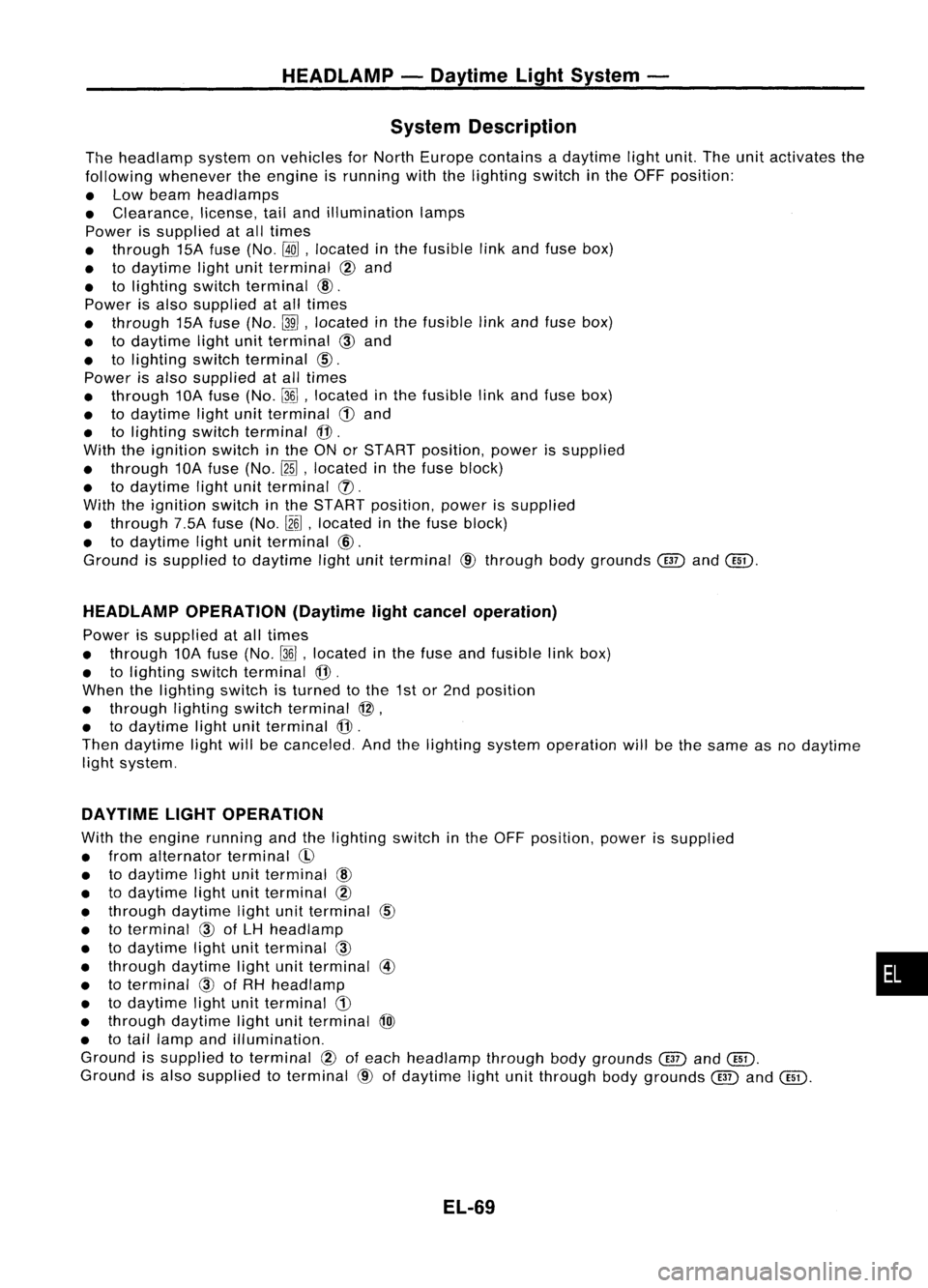
The headlamp systemonvehicles forNorth Europe contains adaytime lightunit.Theunitactivates the
following whenever theengine isrunning withthelighting switchinthe OFF position:
• Low beam headlamps
• Clearance, license,tailand illumination lamps
Power issupplied atall times
• through 15Afuse (No.
@ill,
located inthe fusible linkand fuse box)
• todaytime lightunitterminal @and
• tolighting switchterminal
@.
Power isalso supplied atall times
• through 15Afuse (No.~,located inthe fusible linkand fuse box)
• todaytime lightunitterminal
CID
and
• tolighting switchterminal
CID.
Power isalso supplied atall times
• through 10Afuse (No.~,located inthe fusible linkand fuse box)
• todaytime lightunitterminal
CD
and
• tolighting switchterminal @.
With theignition switchinthe ONorSTART position, powerissupplied
• through 10Afuse (No.~,located inthe fuse block)
• todaytime lightunitterminal (]).
With theignition switchinthe START position, powerissupplied
• through 7.5Afuse(No.
l2~,
located inthe fuse block)
• todaytime lightunitterminal @.
Ground issupplied todaytime lightunitterminal @through bodygrounds
@
and@D.
HEADLAMP OPERATION (Daytimelightcancel operation)
Power issupplied atall times
• through 10Afuse (No.~,located inthe fuse andfusible linkbox)
• tolighting switchterminal
@.
When thelighting switchisturned tothe 1stor2nd position
• through lightingswitchterminal @,
• todaytime lightunitterminal
@.
Then daytime lightwillbecanceled. Andthelighting systemoperation willbethe same asnodaytime
light system.
DAYTIME LIGHTOPERATION
With theengine running andthelighting switchinthe OFF position, powerissupplied
• from alternator terminal
CI>
• todaytime lightunitterminal
@
• todaytime lightunitterminal @
• through daytime lightunitterminal
CID
• toterminal
@)
ofLH headlamp
• todaytime lightunitterminal
CID
• through daytime lightunitterminal @
• toterminal
@)
ofRH headlamp
• todaytime lightunitterminal
CD
• through daytime lightunitterminal
@)
• totail lamp andillumination.
Ground issupplied toterminal
@
ofeach headlamp throughbodygrounds
@
and@D.
Ground isalso supplied toterminal @ofdaytime lightunitthrough bodygrounds
@
and@D.
EL-69
•
Page 446 of 1701
HEADLAMP-Daytime LightSystem -
Trouble Diagnoses (DaytimeLight)
DAYTIME LIGHTCONTROL UNITINSPECTION TABLE
(Input/output operationsignal)
INPUT
(1)/
Voltage
(V)
Terminal No. Connections
OUTPUT
(0)
Operated
condition (Approximate
values)
Power source for
1 illumination
&
tail
- -
12
lamp
2 Power
source for
12
- -
head lamp LH
3
Power
source for
12
-
-
head lamp RH
ON(daytime lightoperating')
12
4
HeadlampRH
0
OFF 0
ON (daytime lightoperating') 12
5
HeadlampLH
0
OFF 0
START 12
6
Startsignal
I
Ignitionswitch
ON,ACC orOFF
0
ON orSTART
12
7
Powersource
-
Ignition
switch
ACCorOFF
0
Alternator "L"ter- Running
12
8
I
Engine
minal Stopped0
9 Ground
- - -
Illumination
&
tail ON
(daytime lightoperating')
12
10 lamp
0
OFF 0
1ST.2ND position
12
11 Lightingswitch
I
OFF 0
': Daytime lightoperating: Lightingswitchin"OFF" position withengine running.
EL-74
Page 485 of 1701

EXTERIORLAMP
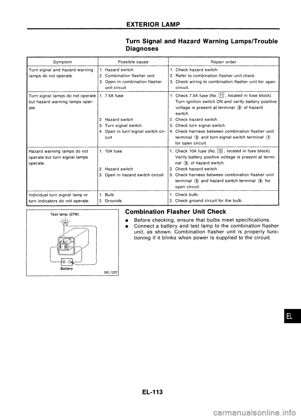
Turn Signal andHazard Warning Lamps/Trouble
Diagnoses
Symptom Possiblecause Repairorder
Turn signal andhazard warning 1.Hazard switch 1.
Check hazard switch.
lamps donot operate.
2.
Combination flasherunit
2.
Refer tocombination flasherunitcheck.
3.
Open incombination flasher
3.
Check
wiringtocombination flasherunitforopen
unit circuit circuit.
Turn signal lampsdonot operate 1.
7.5A fuse 1.Check
7.5Afuse(No.
[ill,
located infuse block).
but hazard warning lampsoper- Turn
ignition switchONand verify battery positive
ate. voltage
ispresent atterminal
@
ofhazard
switch.
2
Hazard
switch
2.
Check hazard switch.
3.
Turn
signal switch
3.
Check
turnsignal switch.
4.
Open
inturn.signal switchcir.
4.
Check
harness between combination flasherunit
cuit terminal
@and turn signal switch terminal
G)
for open circuit.
Hazard warning lampsdonot 1.
10A fuse 1.Check
10Afuse (No.
ffiJ,
located infuse block).
operate butturn signal lamps Verify
battery positive voltageispresent attermi-
operate. nal
@ofhazard switch.
2.
Hazard switch
2.
Check
hazard switch.
3.
Open inhazard switchcircuit
3.
Check
harness between combination flasherunit
terminal @and hazard switchterminal @for
open circuit.
Individual turnsignal lampor 1.
Bulb 1.
Check bulb.
turn indicators donot operate.
2.
Grounds
2.
Check
ground circuitforthe bulb.
Test lamp (27W)
\ I/
, /
Battery
SEL122E
Combination
FlasherUnitCheck
• Before checking, ensurethatbulbs meetspecifications.
• Connect abattery andtestlamp tothe combination flasher
unit, asshown. Combination flasherunitisproperly func-
tioning ifitblinks whenpower issupplied tothe circuit.
EL-113
•