1995 NISSAN ALMERA N15 Thermo
[x] Cancel search: ThermoPage 191 of 1701
__________ PRECAUTIONS ___________
BODYALIGNMENT _
Precautions ForHandling HighStregth Steel Engine
Compartment
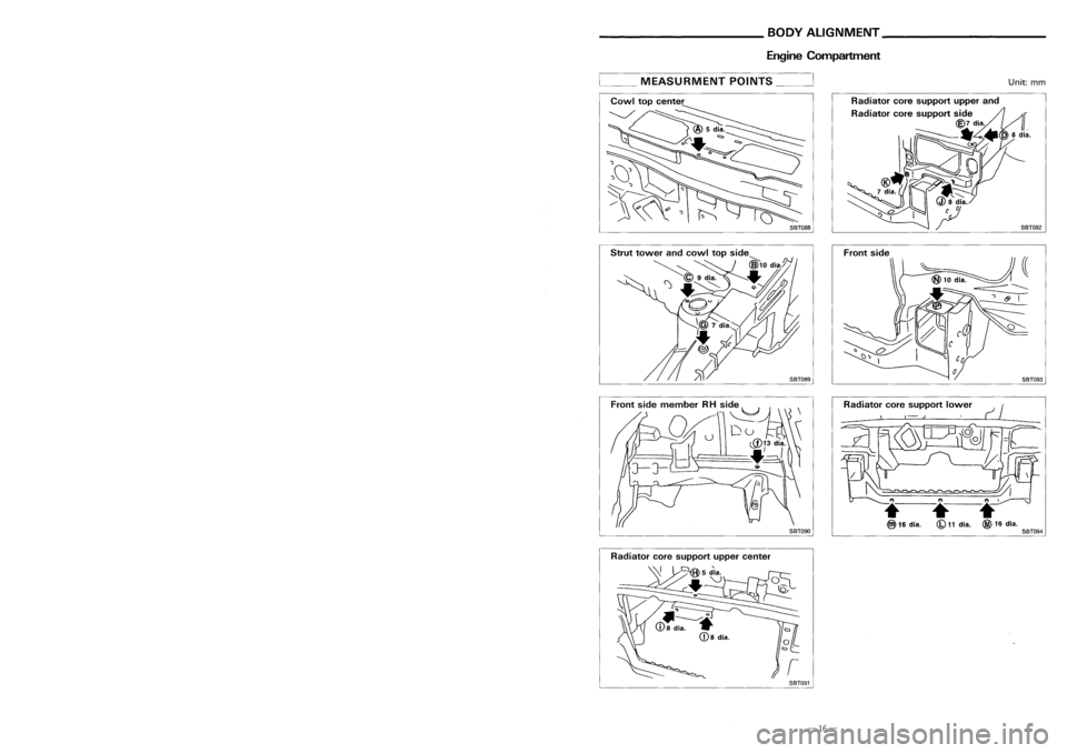
__ MEASURMENT POINTS__
Unit:mm
Front side
SBT088
Traction direction: ...
Not
recommended
• The repair ofreinforcements (suchasside
members) byheating isnot recommended
since itinvolves theriskoflowering strength.
When heating isunavoidable, donot heat
such parts attemperatures above550°C (1,
022°F)
Heating temperature shouldbeverified with
a thermometer. (Acrayon-type andother
thermometer areavailable.)
• When straightening bodypanels, usecaution
in pulling anyHSS panel. Because itis very
strong, thismay cause deformation inadja-
cent portions ofthe body. Inthis case,
increase thenumber ofmeasuring points,
and carefully pulltheHSS panel.
Special
consideration forHSS must begiven tothe following points:
1 .Additional pointstoconsider
• Incutting HSSpanel, avoidgascutting if
possible. Instead,useanairsaw orahand
cutter toavoid decreasing thestrength of
surrounding portionsduetothe influence of
heat. Incase gascutting isinevitable, a
minimum allowance of50 mm (1.97 in)
must begiven.
SBT090
Radiator
coresupport lower
•
(b)
11
dia.
SBT094
• Inwelding HSSpanel, usespot welding
whenever possibleinorder tominimize any
decrease instrength ofsurrounding portions
due tothe influence ofheat.
If spot welding isimpossible, useM.LG.
welding. Donotuseacetylene gaswelding
because itis inferior inwelding strength.
GOOD
-================
N.G.
Never useacetylene .gas
welding.
Radiator
coresupport uppercenter
SBT091
-29-
-16-
Page 195 of 1701
______ HANDLINGPRECAUTIONS FORPLASTICS __________
BODYALIGNMENT _
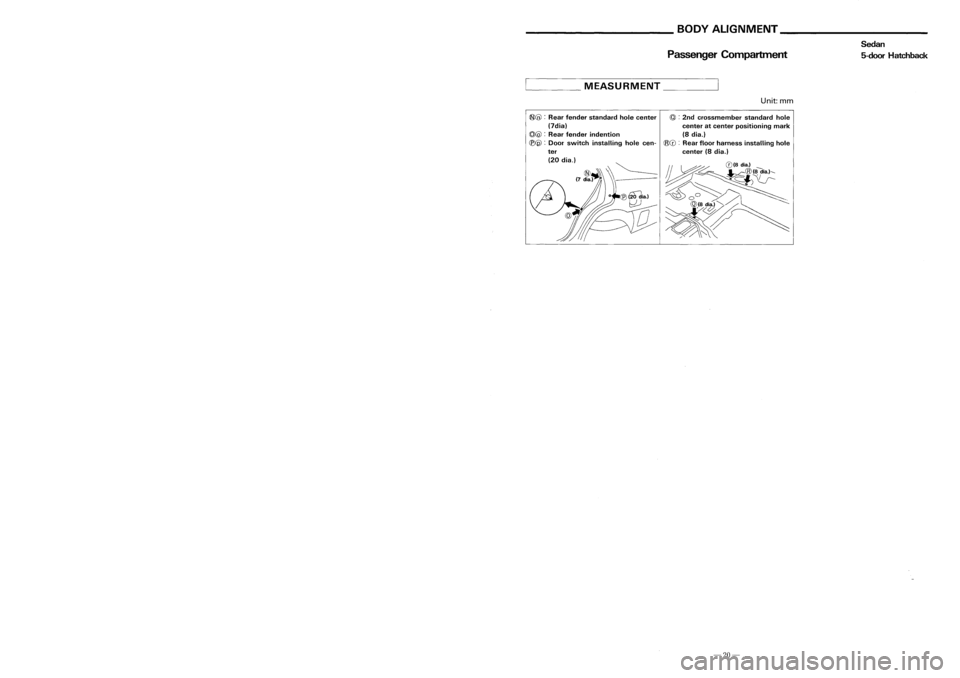
Handling Precautions ForPlastics
Heat resisting
Resistancetogasoline and
Abbreviation Materialname
temperature Othercautions
QC rF)
solvents
PE Polyethylene
80
(176)
Gasoline
andmost solvents
Flammable
are harmless.
PET Polyethylene
180(356)
Gasoline
andmost solvents
terephthalate areharmless.
Gasoline andmost solvents
PVC Polyvinylchloride
80
(176)
are
harmless ifapplied fora
Poison gasisemitted
very short time(wide up
whenburned.
quickly).
pp
Polypropylene
90
(194)
Same
asabove.
Flammable
Also avoid battery acid.
ABS Acrylonitrile
butadiene
80(176)
Avoidgasoline andsolvents.
styrene resin
AES Acrylonitrile
ethylene
80(176)
Avoidgasoline andsolvents.
styrene
PMMA Polymethylmethacrylate
85
(185)
Avoidgasoline andsolvents.
PUR Polyurethane
90
(194)
Gasoline
andmost solvents
Avoidbattery acid.
are harmless.
AAS Acrylonitrile
acrylic
85(185)
Avoidgasoline andsolvents.
ru bber styrene
AS Styrene-a crylo nitri Ie
85
(185)
Avoidgasoline andsolvents.
PPO Polyphenylene oxide
110
(230)
Avoidgasoline .andsolvents.
POM Polyacetal
120
(248)
Gasoline
andsolvents
Avoidbattery acid.
are harmless.
PC Polycarbonate
120
(248)
Avoidgasoline andsolvents.
PA Polyamide(Nylon)
140
(284)
Gasoline
andmost solvents
Avoidimmersing inwater.
are harmless.
FRP Fiberreinforced plastics
170
(338)
Gasoline
andmost solvents
Avoidbattery acid.
are harmless.
PPC Polypropylene composite
115
(239)
Gasoline
andmost solvents
Flammable
are harmless.
PBT Polybutylene terephthalate
140
(284)
Gasoline
andmost solvents
are harmless.
TPR Thermoplastic rubber
80
(176)
Avoidgasoline andsolvents.
TPE Thermoplastic elastomer
80
(176)
Avoidgasoline andsolvents.
TPUR Thermoplastic
80(176)
Avoidgasoline andsolvents.
polyurethane
1 . When repairing andpainting aportion ofthe body adjacent toplastic parts,consider theircharacteristics
(influence ofheat andsolvent) andremove themifnecessary ortake suitable measures toprotect them._
2. Plastic partsshould berepaired andpainted usingmethods suitingthematerials.
-25-
Passenger
Compartment
____ MEASURMENT _
Unit:mm
~@ :
Rear fender standard holecenter
@:
2nd crossmember standardhole
(7dia) centeratcenter positioning mark
(Q)@ :
Rear fender indention (8dia.)
(B@ :
Door switch installing holecen-
@([):
Rearfloor harness installing hole
ter center(8dia.)
(20 dia.) ~
(D<)
~~ ~~'---- ~ k@(fdiaol",
(7 diajj \\1 ~;..·
C')\U--
~ ~O"~Wiaol ~
-Z
J
D~
-20-
Sedan
5-door Hatchback
Page 200 of 1701
______ HANDLINGPRECAUTIONS FORPLASTICS __________
BODYALIGNMENT _
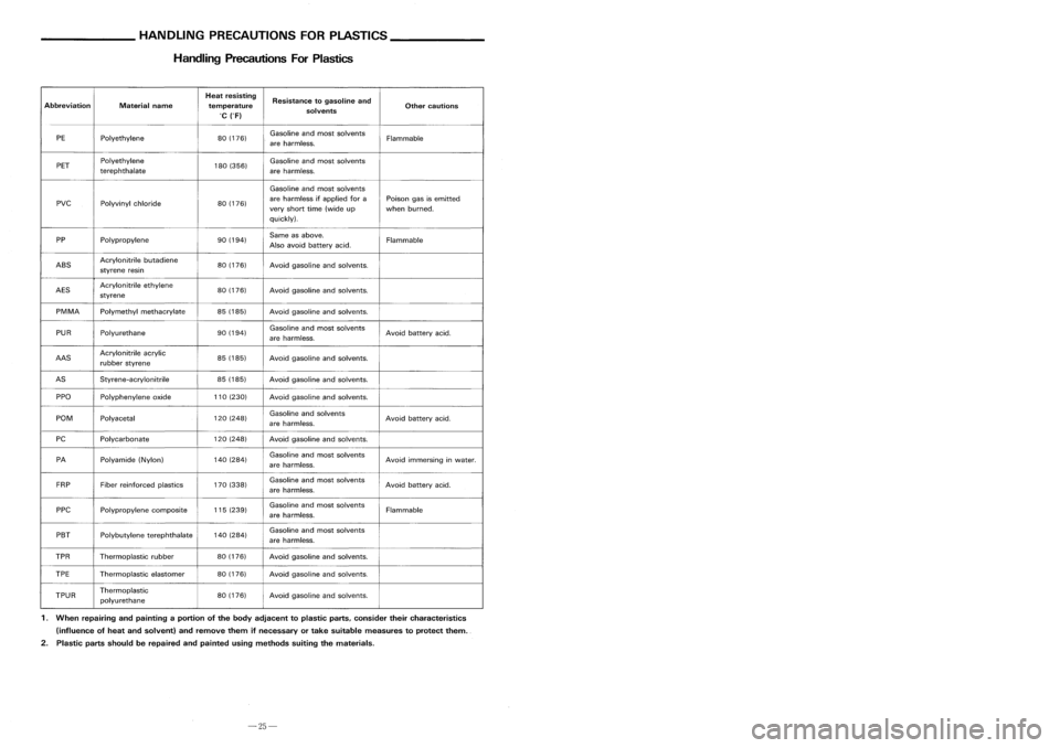
Handling Precautions ForPlastics
Heat resisting
Resistancetogasoline and
Abbreviation Materialname
temperature Othercautions
QC rF)
solvents
PE Polyethylene
80
(176)
Gasoline
andmost solvents
Flammable
are harmless.
PET Polyethylene
180(356)
Gasoline
andmost solvents
terephthalate areharmless.
Gasoline andmost solvents
PVC Polyvinylchloride
80
(176)
are
harmless ifapplied fora
Poison gasisemitted
very short time(wide up
whenburned.
quickly).
pp
Polypropylene
90
(194)
Same
asabove.
Flammable
Also avoid battery acid.
ABS Acrylonitrile
butadiene
80(176)
Avoidgasoline andsolvents.
styrene resin
AES Acrylonitrile
ethylene
80(176)
Avoidgasoline andsolvents.
styrene
PMMA Polymethylmethacrylate
85
(185)
Avoidgasoline andsolvents.
PUR Polyurethane
90
(194)
Gasoline
andmost solvents
Avoidbattery acid.
are harmless.
AAS Acrylonitrile
acrylic
85(185)
Avoidgasoline andsolvents.
ru bber styrene
AS Styrene-a crylo nitri Ie
85
(185)
Avoidgasoline andsolvents.
PPO Polyphenylene oxide
110
(230)
Avoidgasoline .andsolvents.
POM Polyacetal
120
(248)
Gasoline
andsolvents
Avoidbattery acid.
are harmless.
PC Polycarbonate
120
(248)
Avoidgasoline andsolvents.
PA Polyamide(Nylon)
140
(284)
Gasoline
andmost solvents
Avoidimmersing inwater.
are harmless.
FRP Fiberreinforced plastics
170
(338)
Gasoline
andmost solvents
Avoidbattery acid.
are harmless.
PPC Polypropylene composite
115
(239)
Gasoline
andmost solvents
Flammable
are harmless.
PBT Polybutylene terephthalate
140
(284)
Gasoline
andmost solvents
are harmless.
TPR Thermoplastic rubber
80
(176)
Avoidgasoline andsolvents.
TPE Thermoplastic elastomer
80
(176)
Avoidgasoline andsolvents.
TPUR Thermoplastic
80(176)
Avoidgasoline andsolvents.
polyurethane
1 . When repairing andpainting aportion ofthe body adjacent toplastic parts,consider theircharacteristics
(influence ofheat andsolvent) andremove themifnecessary ortake suitable measures toprotect them._
2. Plastic partsshould berepaired andpainted usingmethods suitingthematerials.
-25-
Passenger
Compartment
____ MEASURMENT _
Unit:mm
~@ :
Rear fender standard holecenter
@:
2nd crossmember standardhole
(7dia) centeratcenter positioning mark
(Q)@ :
Rear fender indention (8dia.)
(B@ :
Door switch installing holecen-
@([):
Rearfloor harness installing hole
ter center(8dia.)
(20 dia.) ~
(D<)
~~ ~~'---- ~ k@(fdiaol",
(7 diajj \\1 ~;..·
C')\U--
~ ~O"~Wiaol ~
-Z
J
D~
-20-
Sedan
5-door Hatchback
Page 204 of 1701
__________ PRECAUTIONS ___________
BODYALIGNMENT _
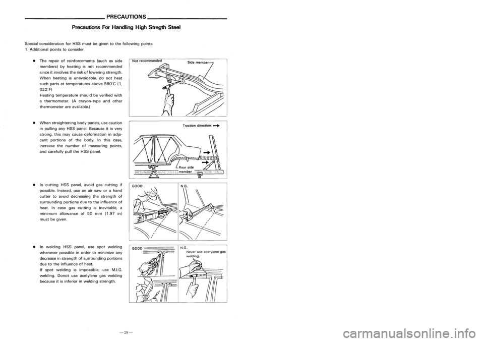
Precautions ForHandling HighStregth Steel Engine
Compartment
__ MEASURMENT POINTS__
Unit:mm
Front side
SBT088
Traction direction: ...
Not
recommended
• The repair ofreinforcements (suchasside
members) byheating isnot recommended
since itinvolves theriskoflowering strength.
When heating isunavoidable, donot heat
such parts attemperatures above550°C (1,
022°F)
Heating temperature shouldbeverified with
a thermometer. (Acrayon-type andother
thermometer areavailable.)
• When straightening bodypanels, usecaution
in pulling anyHSS panel. Because itis very
strong, thismay cause deformation inadja-
cent portions ofthe body. Inthis case,
increase thenumber ofmeasuring points,
and carefully pulltheHSS panel.
Special
consideration forHSS must begiven tothe following points:
1 .Additional pointstoconsider
• Incutting HSSpanel, avoidgascutting if
possible. Instead,useanairsaw orahand
cutter toavoid decreasing thestrength of
surrounding portionsduetothe influence of
heat. Incase gascutting isinevitable, a
minimum allowance of50 mm (1.97 in)
must begiven.
SBT090
Radiator
coresupport lower
•
(b)
11
dia.
SBT094
• Inwelding HSSpanel, usespot welding
whenever possibleinorder tominimize any
decrease instrength ofsurrounding portions
due tothe influence ofheat.
If spot welding isimpossible, useM.LG.
welding. Donotuseacetylene gaswelding
because itis inferior inwelding strength.
GOOD
-================
N.G.
Never useacetylene .gas
welding.
Radiator
coresupport uppercenter
SBT091
-29-
-16-
Page 256 of 1701
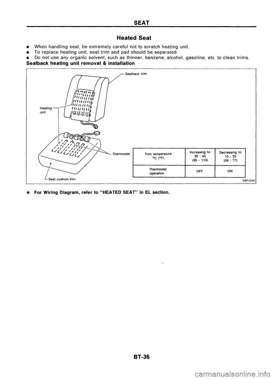
SEAT
Heated Seat
• When handling seat,beextremely carefulnottoscratch heating unit.
• Toreplace heatingunit,seattrimandpadshould beseparated.
• Donot use anyorganic solvent, suchasthinner, benzene, alcohol,gasoline, etc.toclean trims.
Seatback heatingunitremoval
&
installation
Heating
unit Seat
back trim
Trim temperature Increasing
to
Decreasing to
0C (OF) 35
-45
15-25
(95 -113)
(59-77)
Thermostat OFFON
operation
SBF424H
* For Wiring Diagram, referto"HEATED SEAT"inEL section.
8T-36
Page 398 of 1701
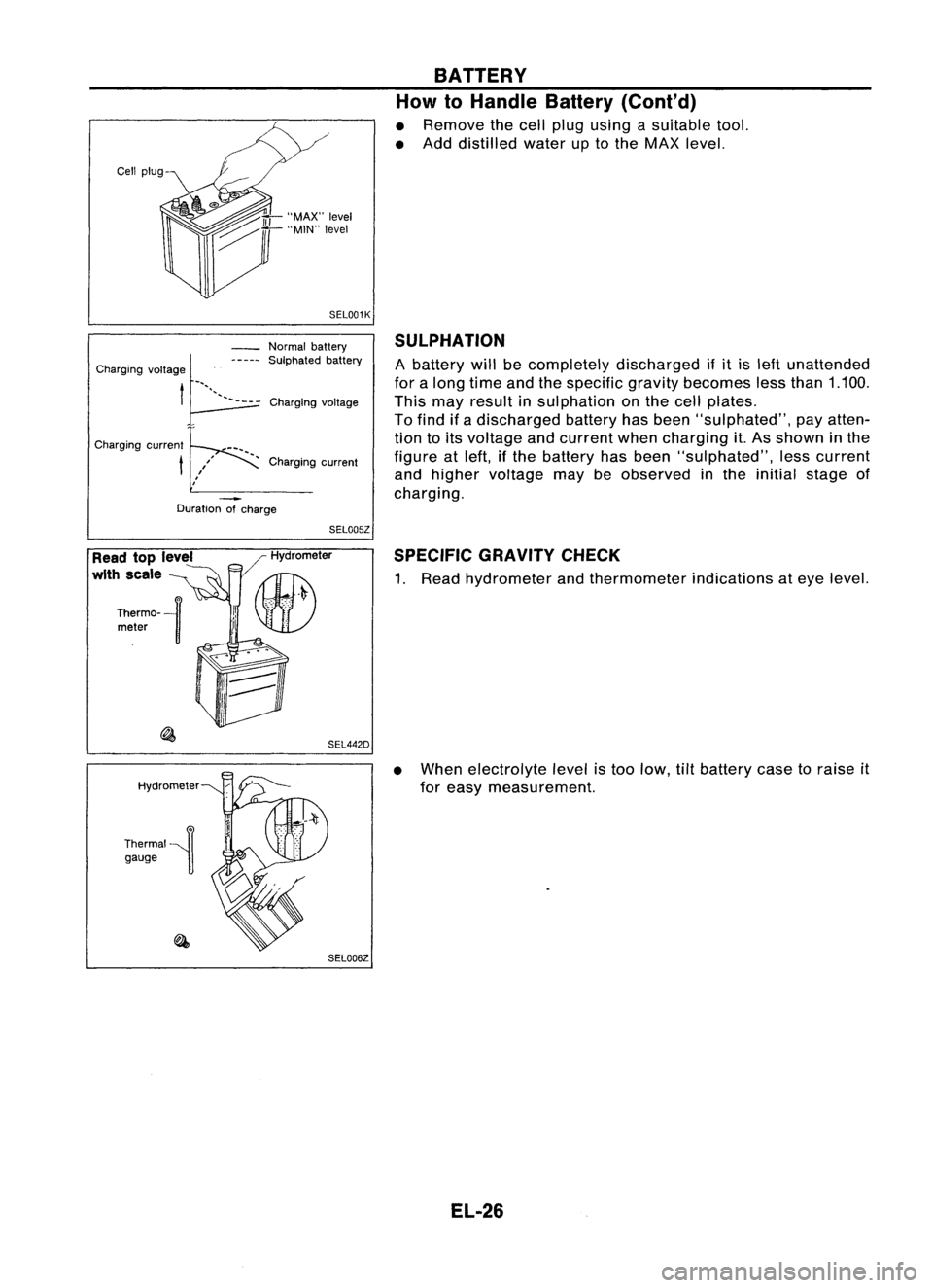
BATTERY
How
10
Handle Battery (Coni'd)
• Remove thecell plug using asuitable tool.
• Add distilled wateruptothe MAX level.
SEL001K
Duration ofcharge
SULPHATION
A battery willbecompletely discharged ifit is left unattended
for along time andthespecific gravitybecomes lessthan 1.100.
This mayresult insulphation onthe cell plates.
To find ifa discharged batteryhasbeen "sulphated", payatten-
tion toits voltage andcurrent whencharging it.As shown inthe
figure atleft, ifthe battery hasbeen "sulphated", lesscurrent
and higher voltage maybeobserved inthe initial stage of
charging.
Charging
voltage
Normal
battery
SUlphated battery
, Charging current
Charging
voltage~_"'"-----
t~
Charging current
t
SEL005Z
Read toplevel
with scale
Hydrometer
Thermal~n gauge ]/
Hydrometer
II~
.' \U)
SEL442DSPECIFIC
GRAVITYCHECK
1. Read hydrometer andthermometer indicationsateye level.
• When electrolyte levelistoo low, tiltbattery casetoraise it
for easy measurement.
SEL006Z
EL-26
Page 787 of 1701
TROUBLEDIAGNOSIS -General Description
*
MONITOR
*
NO FAIL
ENG TEMP SEN 80°C
RECORD
Cam follower
lever
o
SEF214N
SEF147N Fast
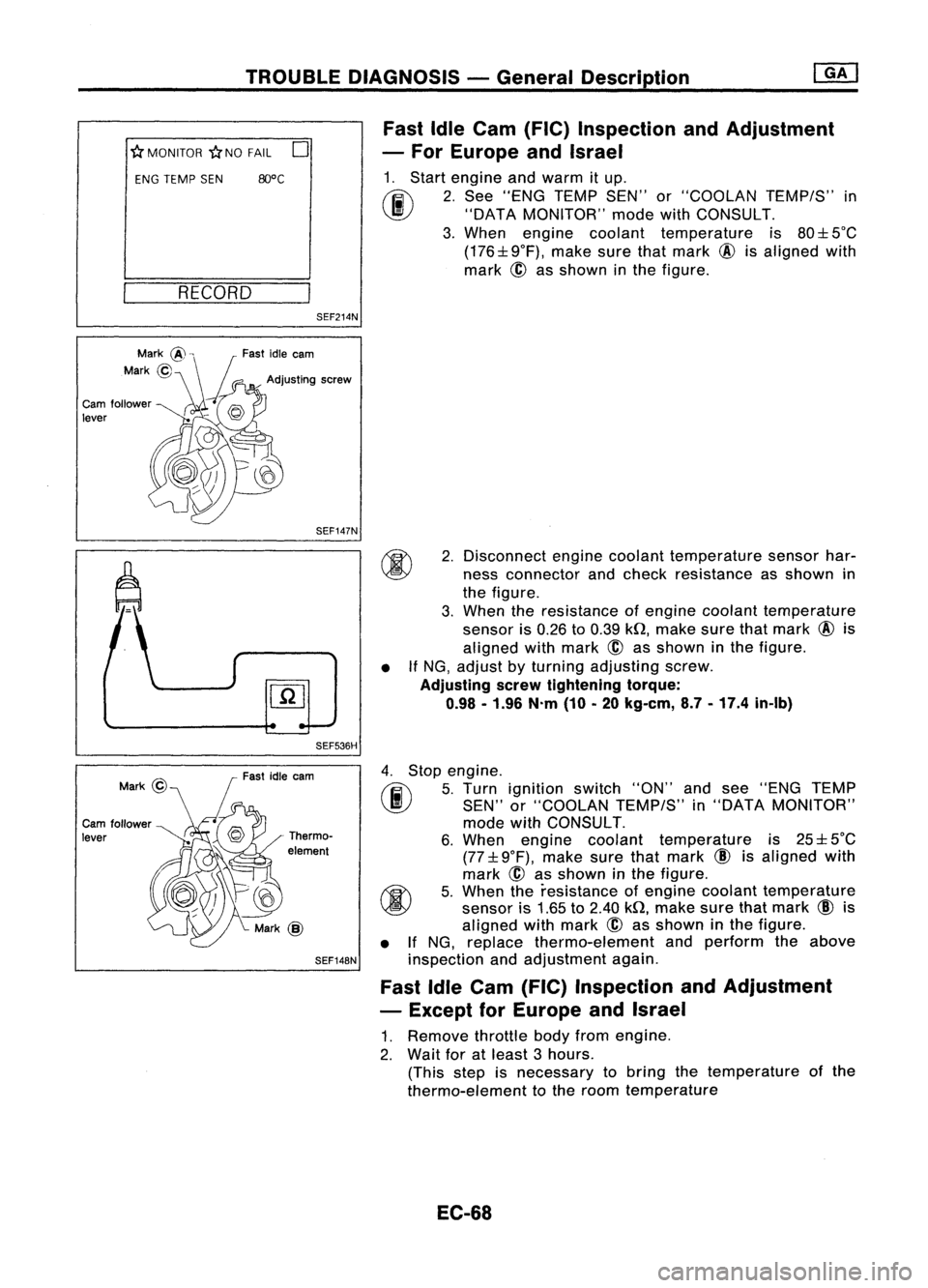
IdleCam (FIC) Inspection andAdjustment
- For Europe andIsrael
1. Start engine andwarm itup.
(ij\
2.See "ENG TEMP SEN"or"COOLAN TEMP/S"in
~ "DATAMONITOR" modewithCONSULT.
3. When engine coolant temperature is80:l: 5°C
(176:l:9°F), makesurethatmark @isaligned with
mark ~asshown inthe figure.
SEF536H •
2.
Disconnect enginecoolant temperature sensorhar-
ness connector andcheck resistance asshown in
the figure.
3. When theresistance ofengine coolant temperature
sensor is0.26 to0.39 kQ,make surethatmark @is
aligned withmark
@
asshown inthe figure.
If NG, adjust byturning adjusting screw.
Adjusting serewtightening torque:
0.98 -1.96 N.m(10-20 kg-em, 8.7-17.4 in-Ib)
Cam follower
lever Fast
idleearn
Thermo-
element
SEF148N
4.
Stop engine.
rF.i\
5.Turn ignition switch"ON"andsee "ENG TEMP
~ SEN"or"COOLAN TEMP/S"in"DATA MONITOR"
mode withCONSULT.
6. When engine coolant temperature is25:l: 5°C
(77:l: 9°F), make surethatmark
CID
isaligned with
mark @asshown inthe figure.
~ 5.When theresistance ofengine coolant temperature
~ sensoris1.65 to2.40 kQ,make surethatmark
CID
is
aligned withmark
@
asshown inthe figure.
• IfNG, replace thermo-element andperform theabove
inspection andadjustment again.
Fast IdleCam (FIC) Inspection andAdjustment
- Except forEurope andIsrael
1. Remove throttlebodyfromengine.
2. Wait foratleast 3hours.
(This stepisnecessary tobring thetemperature ofthe
thermo-element tothe room temperature
EC-68
Page 788 of 1701
•
2**
5*
Go
tostep
L:
Thermo-element stroke
*: Thermo-element isnormal. Adjustfirstidlecam only.
**: Thermo-element ismalfunctioning. Replacethermo-element, andperform
inspection beginningwithstep 2.
TROUBLE
DIAGNOSIS -General Description ~
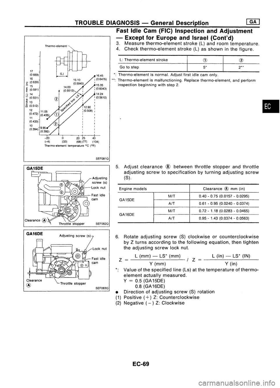
Fast IdleCam (FIC) Inspection andAdjustment
- Except forEurope andIsrael (Cont'd)
3. Measure thermo-element stroke(L)and room temperature.
4. Check thermo-element stroke(L)asshown inthe figure.
Thermo-element
1645
1(0.6476)
I
15.35
: (06043)
'14.24
: (05610)
I
: 1290 :
I
(0.508)
I
I I
I I
I I
: I
I
r
I
r
r
I
I
I
-20 02025 40
HI (32)(68)(77) (104)
Thermo-element temperature°C(OF)
17
(0.669)
16
C (0630)
"" 15
~ (0591)
::J
14
-; (0.551)
t5
13
fJi
(0.512)
12 11.05
(0472) (0435)
11
(0433)
10
(0.394) 9.95
(0.392)
SEF0810
GA15DE
*.
GA16DE
Clearance
@ Adjusting
screw (s)
Lock nut
Fast idle
carn
SEF0820
SEF0830
5.
Adjust clearance
@
between throttlestopper andthrottle
adjusting screwtospecification byturning adjusting screw
(8).
Engine models Clearance
@
mm (in)
M/T 0.40-0.75 (0.0157 -0.0295)
GA15DE A/T0.61
-0.95 (0.0240 -0.0374)
M/T 0.72
-1.18 (0.0283 -0.0465)
GA16DE
A/T0.95
-1.43 (0.0374 -0.0563)
6. Rotate adjusting screw(8)clockwise orcounterclockwise
by Zturns according tothe following equation, thentighten
the adjusting screwlocknut.
L (mm) -L8* (mm) L(in) -L8* (IN)
Z =-------~ /Z =--------
Y
(mm)
Y
(in)
Value ofthe specified line(Ls) atthe temperature ofthermo-
element actuallymeasured.
Y
=
0.5 (GA 15DE)
0.8 (GA 16DE)
• Direction ofadjusting screw(8)rotation
(1) Positive (+)Z:Counterclockwise
(2) Negative (- )Z: Clockwise
EC-69