Page 1190 of 1701
OUTERCOMPONENT PARTS
COJ
15.7 -20.6 (1.60 -2.10, 11.58 -15.19)
•
7
SEM223F
~
9 -
~~~/~ ->
. f'
!il6.28 _8.34 (0.641 -0.851, 55.6-73.9)
~ 6.28.8.34 (0.641-0.851, 55.6-
73.9)-.1
COJ
15.7 -20.6
* :
Refer to"Tightening Order".
~: N.m(kg-m. ft-Ib)
~: N.m(kg-m. in-Ib)
~ :Apply
liquidgasket.
GA16DE
WITHVTC
SEC.
130.140.150.210.211.221.226.253 ~
~ ,... -26.5
{2.1' -'.70,
:5.19 _19.5Sl-\,,4
r
G)
Oilpressure switch
@ Knock sensor
@
Distributor
@
VTCsolenoid valve
@
Intake manifold gasket
@
Intake manifold assembly
(J)
Water pump
@
Thermostat housing
@
Thermostat
EM-11
Page 1200 of 1701

Looseninnumerical order.
SEM546D TIMING
CHAIN @KJ
Removal (Cont'd)
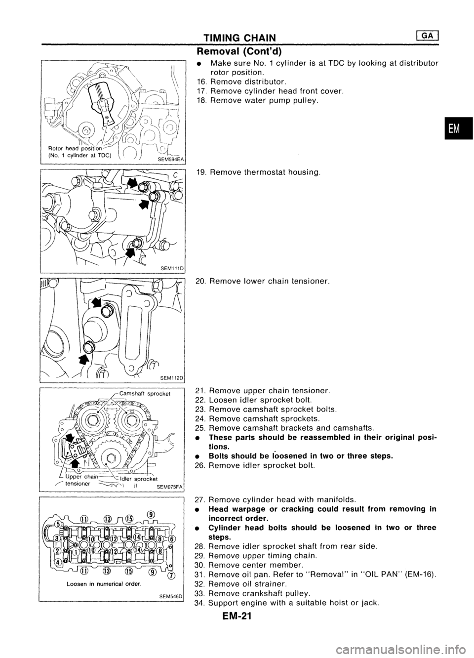
• Make sureNo.1 cylinder isat TDC bylooking atdistributor
rotor position.
16. Remove distributor.
17. Remove cylinder headfrontcover.
18. Remove waterpumppulley.
19. Remove thermostat housing.
20. Remove lowerchaintensioner.
21. Remove upperchaintensioner.
22. Loosen idlersprocket bolt.
23. Remove camshaft sprocketbolts.
24. Remove camshaft sprockets.
25. Remove camshaft bracketsandcamshafts.
• These partsshould bereassembled intheir original posi-
tions.
• Bolts should beloosened intwo orthree steps.
26. Remove idlersprocket bolt.
27. Remove cylinderheadwithmanifolds.
• Head warpage orcracking couldresult fromremoving in
incorrect order.
• Cylinder headboltsshould beloosened intwo orthree
steps.
28. Remove idlersprocket shaftfromrearside.
29. Remove uppertiming chain.
30. Remove centermember.
31. Remove oilpan. Refer to"Removal" in"OIL PAN" (EM-16).
32. Remove oilstrainer.
33. Remove crankshaft pulley.
34. Support enginewithasuitable hoistorjack.
EM-21
•
Page 1206 of 1701
•:Mating mark(different color) 16
rollers
SEM129F TIMING
CHAIN
@K]
Installation
(Cont'd)
19. Assemble camshaftsprocketwithchain.
• Set timing chainbyaligning matingmarkswiththose of
camshaft sprockets.
• Make suresprocket's matingmarksfaceengine front.
20. Install camshaft sprocketbolts.
• Apply newengine oiltobolt threads andseat surface .
•
SEM657D
2.0.3.0
mm
(0.079 -0.118 In)
21.
Install upperchaintensioner.
• Before installing chaintensioner, insertasuitable pininto
pin hole ofchain tensioner.
• After installing chaintensioner, removethepin.
22. Install lowerchaintensioner.
CAUTION:
• Check noproblems occurwhenengine isrotated.
• Make surethatNo.1piston isset atTOC onitscompres-
sion stroke.
• Make sureofthe direction ofthe gasket beforeinstalling
lower chaintensioner.
23. Apply liquidgasket tothermostat housing.
• Use Genuine LiquidGasket orequivalent.
24. Install thermostat housing.
25. Install waterpump pulley.
EM-27
Page 1238 of 1701

OUTERCOMPONENT PARTS
•
SEM231F
SEC.
130-140-150-210-211-221
~ __to:J
13•16 (1.3 -1.6, 9.12)
to:J
16•21 (1.6. 2.1,12. 15)
to:J
20•29
(2.0 •3.0,
14 .22)
to:J
41-52 (4.2 -5.3, 30-38)
~---- D_?
. 'J ~
~~~ 0
-t::;-.....~ /,
0
to:J
21-26 ./"
(2.1. 2.7, ,./"~/'
12 -1~)
fs\
19-~~7
~ to:J
16•21
Q
to:J
18. 21 ,
to:J
45_60 (1.6-2.1, 0
Ii]
6.3 _8.3
(1.8 •2.1, (4.6•6.1, 12•15)
1
(0.64•0.85,
to:J
16•19 13-15)
to:J
16•21 33•44)
(1.6 -1.9, (1.6-2.1,
to:J
16•21
12 -14)
12•15)
t"J
16•,.
f"-~
t"J
15•21
r::!
*
H
...----4lJ
~~'. '1~
J
r \~ ~~'..,:;
1,
~Q.
/¥i-;:
--'Il
1il3.7 -5.0
J~
--A)
to:J
16-21
~11V>/
(0.38 _0.51, A~ - (1.6.2.1,12•15)\...,//
~to:J
20.29(2.0-3.0, 14-22)
33.0 •44.3)
Y
&'/-
:f~l
to:J
20•26 (2.0 •2.7, 14-20)
to:J :
N'm (kg-m, fl-Ib)
to:J
16-21 (1.6 -2.1, 12-15)~/
Ii] :
N'm (kg-m, in-Ib) •
~ :Apply
liquidgasket.
*:
Refer toLC section
("Thermostat", "ENGINECOOLING SYSTEM").
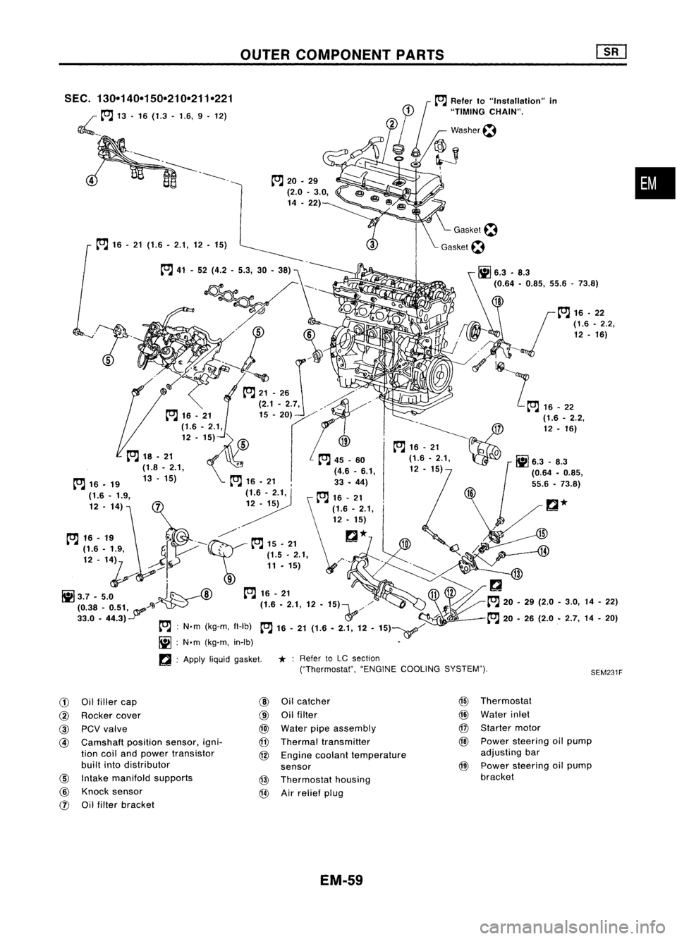
G)
Oilfiller cap
@
Oilcatcher
@
Thermostat
@
Rocker cover
@
Oilfilter
@
Water inlet
@
PCVvalve
@
Water pipeassembly
@
Starter motor
@
Camshaft
positionsensor,igni-
@
Thermal transmitter
@
Power steering oilpump
tion coiland power transistor
@
Engine coolant temperature adjusting
bar
built intodistributor
sensor
@
Power
steering oilpump
@
Intake manifold supports
@
Thermostat housing bracket
@
Knock sensor
@
Airrelief plug
rJ)
Oilfilter bracket
EM-59
Page 1266 of 1701
CYLINDERHEAD
Disassembly (Cont'd)
6. Remove intakemanifold supports.
7. Remove fueltube assembly.
Refer to"Injector Removal andInstallation" inEC section.
8. Remove intakemanifold.
•
Intake manifold
collector Looseninnumerical order.
SEM607E
- Thermostat housing
SEM785E
9.
Remove intakemanifold collectorfromintake manifold.
10. Remove thermostat housingwithwater pipe.
11. Remove valvecomponents withTool.
EM-87
Page 1273 of 1701
![NISSAN ALMERA N15 1995 Service Manual CYLINDERHEAD [][]
Assembly (Cont'd)
2. Install intakemanifold.
3. Install fueltube assembly.
Refer to"Injector RemovalandInstallation" inEC section.
Intake manifold
collector Tighteninnum NISSAN ALMERA N15 1995 Service Manual CYLINDERHEAD [][]
Assembly (Cont'd)
2. Install intakemanifold.
3. Install fueltube assembly.
Refer to"Injector RemovalandInstallation" inEC section.
Intake manifold
collector Tighteninnum](/manual-img/5/57349/w960_57349-1272.png)
CYLINDERHEAD [][]
Assembly (Cont'd)
2. Install intakemanifold.
3. Install fueltube assembly.
Refer to"Injector RemovalandInstallation" inEC section.
Intake manifold
collector Tighteninnumerical order.
SEM610E
SEM786E
SEM594D
Thermostat
housing 4.
Install thermostat housingwithwater pipe.
• Tightening procedure:
1) Tighten bolt
@
to2-5 N'm (0.2-0.5 kg-m, 1.4-3.6 ft-Ib).
2) .Tighten bolt
@
to16-21 N'm (1.6-2.1 kg-m, 12-15 ft-Ib).
3) Tighten bolt
@
to16-21 N'm (1.6-2.1 kg-m, 12-15 ft-Ib).
4) Tighten bolt
CID
to16-21 N'm (1.6-2.1 kg-m, 12-15 ft-Ib).
5. Install exhaust manifold.
6. Install exhaust manifold cover.
7. Install wateroutlet.
a. Before installing wateroutlet, remove alltraces ofliquid
gasket frommating surface usingascraper.
• Also remove tracesofliquid gasket frommating surface of
cylinder head.
b. Apply acontinuous beadofliquid gasket tomating surface
of water outlet.
• Use Genuine LiquidGasket orequivalent.
~ Liquid gasket
SEM086D
8.Install intakemanifold supports.
9. Install crankcase ventilation oilseparator.
EM-94
Page 1292 of 1701
Rightside
SEC. 130.135.185.186.210.213.233
~: N.m(kg-m. in-Ib)
[ClJ :
N.m (kg-m. ft-Ib)
OUTER
COMPONENT PARTS
I~
16-21
(1.6 -2.1,
12-
15)7
I
.~
SEM044FA
•
G)
Starter motor
@
Injection pump
@
Injection tube
@
Thermostat housing
@
Injection nozzle
@
Spill tube
!J)
Water outlet
@
Beltcover
EM-113
@
Timing belt
@
Injection pumpsprocket
@
Rear camshaft sprocket
@
Rear backcover
@
Oilcooler
@
Gasket
Page 1412 of 1701

DESCRIPTION
Refrigeration Cycle
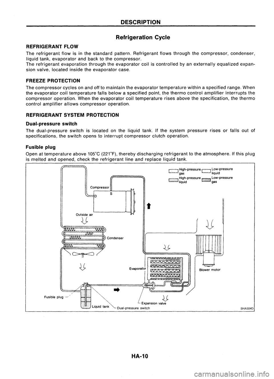
REFRIGERANT FLOW
The refrigerant flowisinthe standard pattern.Refrigerant flowsthrough thecompressor, condenser,
liquid tank,evaporator andback tothe compressor.
The refrigerant evaporation throughtheevaporator coiliscontrolled byan externally equalizedexpan-
sion valve, located insidetheevaporator case.
FREEZE PROTECTION
The compressor cyclesonand offtomaintain theevaporator temperature withinaspecified range.When
the evaporator coiltemperature fallsbelow aspecified point,thethermo controlamplifier interrupts the
compressor operation.Whentheevaporator coiltemperature risesabove thespecification, thethermo
control amplifier allowscompressor operation.
REFRIGERANT SYSTEMPROTECTION
Dual-pressure switch
The dual-pressure switchislocated onthe liquid tank.Ifthe system pressure risesorfalls outof
specifications, theswitch openstointerrupt compressor clutchoperation.
Fusible plug
Open attemperature above105°C(221°F), thereby discharging refrigeranttothe atmosphere. Ifthis plug
is melted andopened, checktherefrigerant lineand replace liquidtank.
c:::::.J
High-pressure
EJ
Low-pressure
gas liquid
1:-:-:-:-::-:-::-:-:1
~~~~pressure
!::i'i'i':}':J
~~:-pressure
Compressor
D
Outside air
U
s
t
Fusible plug-~
~..
U
'" Expansionvalve
Liquid tank"'--Dual-pressure switch
HA-10
Blower
motor
SHA504D